EP2092996A1 - Verfahren und Vorrichtung für Turbinenschaufeln einschliesslich Dichtung - Google Patents
Verfahren und Vorrichtung für Turbinenschaufeln einschliesslich Dichtung Download PDFInfo
- Publication number
- EP2092996A1 EP2092996A1 EP20090250238 EP09250238A EP2092996A1 EP 2092996 A1 EP2092996 A1 EP 2092996A1 EP 20090250238 EP20090250238 EP 20090250238 EP 09250238 A EP09250238 A EP 09250238A EP 2092996 A1 EP2092996 A1 EP 2092996A1
- Authority
- EP
- European Patent Office
- Prior art keywords
- labyrinth seal
- seal portion
- cavity
- investment casting
- casting mold
- Prior art date
- Legal status (The legal status is an assumption and is not a legal conclusion. Google has not performed a legal analysis and makes no representation as to the accuracy of the status listed.)
- Granted
Links
Images


Classifications
-
- F—MECHANICAL ENGINEERING; LIGHTING; HEATING; WEAPONS; BLASTING
- F01—MACHINES OR ENGINES IN GENERAL; ENGINE PLANTS IN GENERAL; STEAM ENGINES
- F01D—NON-POSITIVE DISPLACEMENT MACHINES OR ENGINES, e.g. STEAM TURBINES
- F01D5/00—Blades; Blade-carrying members; Heating, heat-insulating, cooling or antivibration means on the blades or the members
- F01D5/12—Blades
- F01D5/14—Form or construction
-
- B—PERFORMING OPERATIONS; TRANSPORTING
- B22—CASTING; POWDER METALLURGY
- B22C—FOUNDRY MOULDING
- B22C7/00—Patterns; Manufacture thereof so far as not provided for in other classes
- B22C7/02—Lost patterns
-
- B—PERFORMING OPERATIONS; TRANSPORTING
- B22—CASTING; POWDER METALLURGY
- B22C—FOUNDRY MOULDING
- B22C9/00—Moulds or cores; Moulding processes
- B22C9/02—Sand moulds or like moulds for shaped castings
- B22C9/04—Use of lost patterns
-
- C—CHEMISTRY; METALLURGY
- C30—CRYSTAL GROWTH
- C30B—SINGLE-CRYSTAL GROWTH; UNIDIRECTIONAL SOLIDIFICATION OF EUTECTIC MATERIAL OR UNIDIRECTIONAL DEMIXING OF EUTECTOID MATERIAL; REFINING BY ZONE-MELTING OF MATERIAL; PRODUCTION OF A HOMOGENEOUS POLYCRYSTALLINE MATERIAL WITH DEFINED STRUCTURE; SINGLE CRYSTALS OR HOMOGENEOUS POLYCRYSTALLINE MATERIAL WITH DEFINED STRUCTURE; AFTER-TREATMENT OF SINGLE CRYSTALS OR A HOMOGENEOUS POLYCRYSTALLINE MATERIAL WITH DEFINED STRUCTURE; APPARATUS THEREFOR
- C30B11/00—Single-crystal growth by normal freezing or freezing under temperature gradient, e.g. Bridgman-Stockbarger method
- C30B11/002—Crucibles or containers for supporting the melt
-
- C—CHEMISTRY; METALLURGY
- C30—CRYSTAL GROWTH
- C30B—SINGLE-CRYSTAL GROWTH; UNIDIRECTIONAL SOLIDIFICATION OF EUTECTIC MATERIAL OR UNIDIRECTIONAL DEMIXING OF EUTECTOID MATERIAL; REFINING BY ZONE-MELTING OF MATERIAL; PRODUCTION OF A HOMOGENEOUS POLYCRYSTALLINE MATERIAL WITH DEFINED STRUCTURE; SINGLE CRYSTALS OR HOMOGENEOUS POLYCRYSTALLINE MATERIAL WITH DEFINED STRUCTURE; AFTER-TREATMENT OF SINGLE CRYSTALS OR A HOMOGENEOUS POLYCRYSTALLINE MATERIAL WITH DEFINED STRUCTURE; APPARATUS THEREFOR
- C30B29/00—Single crystals or homogeneous polycrystalline material with defined structure characterised by the material or by their shape
- C30B29/10—Inorganic compounds or compositions
- C30B29/52—Alloys
-
- F—MECHANICAL ENGINEERING; LIGHTING; HEATING; WEAPONS; BLASTING
- F01—MACHINES OR ENGINES IN GENERAL; ENGINE PLANTS IN GENERAL; STEAM ENGINES
- F01D—NON-POSITIVE DISPLACEMENT MACHINES OR ENGINES, e.g. STEAM TURBINES
- F01D5/00—Blades; Blade-carrying members; Heating, heat-insulating, cooling or antivibration means on the blades or the members
- F01D5/12—Blades
- F01D5/14—Form or construction
- F01D5/147—Construction, i.e. structural features, e.g. of weight-saving hollow blades
-
- F—MECHANICAL ENGINEERING; LIGHTING; HEATING; WEAPONS; BLASTING
- F05—INDEXING SCHEMES RELATING TO ENGINES OR PUMPS IN VARIOUS SUBCLASSES OF CLASSES F01-F04
- F05D—INDEXING SCHEME FOR ASPECTS RELATING TO NON-POSITIVE-DISPLACEMENT MACHINES OR ENGINES, GAS-TURBINES OR JET-PROPULSION PLANTS
- F05D2230/00—Manufacture
- F05D2230/20—Manufacture essentially without removing material
- F05D2230/21—Manufacture essentially without removing material by casting
-
- Y—GENERAL TAGGING OF NEW TECHNOLOGICAL DEVELOPMENTS; GENERAL TAGGING OF CROSS-SECTIONAL TECHNOLOGIES SPANNING OVER SEVERAL SECTIONS OF THE IPC; TECHNICAL SUBJECTS COVERED BY FORMER USPC CROSS-REFERENCE ART COLLECTIONS [XRACs] AND DIGESTS
- Y10—TECHNICAL SUBJECTS COVERED BY FORMER USPC
- Y10T—TECHNICAL SUBJECTS COVERED BY FORMER US CLASSIFICATION
- Y10T428/00—Stock material or miscellaneous articles
- Y10T428/12—All metal or with adjacent metals
Definitions
- the present invention relates to a method and apparatus for producing turbine single-crystal gas turbine engine components having integral sealing structures.
- Gas turbine engines include a number of blades and vanes that interact with fluids moving through these engines.
- seals such a stand-alone labyrinth seal disks have been attached to rotor disks carrying turbine blades, using bolts or other means. These labyrinth seal disks can provide air seals between the rotating structures associated with the blades and adjacent non-rotating structures, which typically include a non-rotating abradable seal structure positioned in close proximity to outwardly extending portions of the rotating labyrinth seal disk.
- labyrinth sealing structures such as knife edges and hammerheads that extend outward from root portions of turbine blades presents a number of problems.
- the blade can be cast in a rough, relatively imprecise manner and then machined to desired shapes and dimensions with precision, forming the labyrinth sealing structures solely by way of the machining process.
- the configuration of typical turbine blades can make machining of labyrinth sealing structures difficult or impossible, or can undesirably limit design options for the labyrinth sealing structures.
- a platform of a turbine blade can extend outward in such a way that machining tools cannot be maneuvered to form desired labyrinth sealing structures located in close proximity to the platform, due to obstruction by the platform.
- An investment casting mold article includes a wall for retaining casting material and a cavity defined by the wall.
- the cavity includes an airfoil portion, a root portion adjacent to the airfoil portion, and a labyrinth seal portion extending from the root portion.
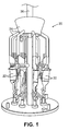
- FIG. 1 is a perspective view of an investment casting mold assembly according to an embodiment of the present invention.
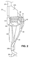
- FIG. 2 is a perspective view of a portion of the investment casting mold assembly of FIG. 1 .
- FIG. 3 is a perspective view of the portion of the investment casting mold assembly of FIG. 2 , with indications of possible grain jumper notch locations.
- FIG. 4 is a side view of a wax investment casting form according to the present invention utilizing a strongback core.
- the present invention provides an apparatus and method for producing single-crystal turbine blades through investment casting such that the blades are substantially in a finished state as-cast.
- These as-cast turbine blades can include sealing structures such as knife edges and hammerheads that are relatively long and slender and extend outward from a root portion of the blade.
- grain jumpers are used to help promote a single-crystal grain structure through the sealing structures.
- gussets and/or strongback cores are used in an investment casting mold to promote dimensional stability and maintain true position of features of as-cast blades.
- FIG. 1 is a perspective view of an exemplary embodiment of an investment casting mold assembly 20 that includes eight individual turbine blade investment casting molds 22 connected to a common alloy feed gate subassembly 24 and a support jig 26. It should be understood that the number of individual investment casting molds 22 in the assembly 20 can vary as desired, and the configuration of the assembly 20 can vary as desired for particular applications.
- the molds 22 constitute walls for retaining casting material within one or more cavities defined within those walls as those familiar with investment casting will readily appreciate. Examples of resultant turbine blade shapes with labyrinth seal structures (e.g., knife edges and hammerheads) produced with the molds 22 are disclosed in commonly-assigned U.S. Pat. App. Pub. Nos. 2006/0275106A1 , 2006/0275107A1 , 2006/0275108A1 , and 2007/0098545A1 .
- FIG. 2 is a perspective view of one of the individual turbine blade investment casting molds 22 of the investment casting mold assembly 20.
- the other individual turbine blade investment casting molds 22 of the assembly 20 can be configured substantially the same as that one illustrated in FIG. 2 .
- Each mold 22 includes a grain-selection structure 28, an airfoil portion 30, a root portion 32, and a labyrinth seal portion 34 extending from a leading edge side of the root portion 32.
- the mold 22 also includes a platform portion 36 located between the airfoil portion 30 and the root portion 32, stock portions 37A and 37B, as well as a gusset portion 38 extending from the labyrinth seal portion 34.
- One or more grain jumpers 40 having notches 42 therein are connected from the stock portion 37B near the grain selection structure 28 to the labyrinth seal portion 34.
- the grain selection structure 28 can be a conventional helical tube structure or "pig-tail” that encourages growth of a uniform "single crystal” crystallographic grain structure orientation of metallic material in the mold during solidification from a molten state.
- the grain selection structure 28 is generally located at the bottom of the mold 22, and would be the first portion of the mold 22 cooling during solidification, as explained further below.
- the airfoil portion 30 is used to define a thin, aerodynamically shaped airfoil of a blade produced with the mold 22.
- the root portion 32 can include a dovetail, firtree, or other blade retention structure, and in alternative embodiments can include an optional radially-extending shank portion (not shown).
- the platform portion 36 defines a radially-inward gas path boundary of the blade produced with the mold 22.
- the stock portions 37A and 37B result in additional material being cast with the desired turbine blade shape. These stock portions 37A and 38B aid casting material feeding into the mold 22 and aid single-crystal grain growth.
- stock can be added to a trailing edge side of the root portion 32, to pressure and suction sides of the labyrinth seal portion 34 at a depth of 0.127 mm (0.005 inch), and to other desired locations to aid grain growth.
- material formed at these stock portions can be removed by machining. Material removal at these locations is relatively simple, because these stock portions are arranged along the cast turbine blade where machining tooling is not obstructed by protruding blade features, and the machining tooling does not need to form complex shapes requiring great accuracy.
- the gusset 38 can be formed in a generally triangular shape of approximately 1.27 mm (0.050 inch) in thickness, connecting the labyrinth seal portion 34 and the root portion 32.
- the gusset 38 helps aid casting material feeding into the mold 22 and promote dimensional and true position stability to the labyrinth seal portion 34 during casting material solidification.
- the grain jumpers 40 are tube-like gates that can be connected between different portions of the mold 22 to promote desired single-crystal grain structure growth. It is known that single-crystal grain structure growth is impeded with relatively small, elongated portions of a mold extending in a downward direction (relative to the orientation of the mold assembly during solidification), because those downwardly-extending portions can solidify independent of material in other portions of the mold and can thereby undesirably produce grain structures other than single-crystal grain structures. In order to reduce such difficulties, the grain jumpers 40 are positioned to provide generally vertically-oriented paths of molten material that extend to the generally downwardly-oriented regions of the labyrinth seal portion 34. The grain jumpers 40 can also connect to the platform portion 36 of the mold 22, as shown in the embodiment in FIG. 3 .
- the solidification of material within the grain jumpers 40 could exert stress upon the labyrinth seal portion 34 and undesirably alter the true position of one or more features of the labyrinth seal portion 34.
- Tolerances of the labyrinth seal portion 34 are relatively tight, with design tolerances of plus or minus 0.0508 mm (0.002 inch) for the true position of tips of labyrinth seals features formed by the labyrinth seal portion 34.
- notches 42 can be formed in the grain jumpers 40 to encourage solidifying material to break apart along the length of the grain jumpers 40 rather than exert pressure on the labyrinth seal portion 34.
- FIG. 3 is a perspective view of one investment casting mold 22, with indications of exemplary locations 42A-42F for the notches 42 in the grain jumpers 40. It is generally desired that notches be provided between any two connection points of the grain jumpers 40 and along each branch of the grain jumpers 40. For instance, notch locations 42A and 42B are present on each grain jumper 40 branch between the stock portion 37B and the platform portion 36, and notch locations 42C-42F are present on each grain jumper 40 branch between the platform portion 36 and the labyrinth seal portion 34. Preferably, the notch locations 42A-42F are at approximately 50% span between attachment points of the grain jumpers 40. However, it should be recognized that location, positioning and configuration of the grain jumpers 40 and the notches 42 can vary as desired for particular applications.
- the investment casting mold 22 can be fabricated to a desired shape and configuration using, for example, conventional lost-wax materials and techniques that are well-known in the art. Ceramic cores embedded in the wax can optionally be utilized to produce internal cavities or passageways in the resultant turbine blade, in a known manner.
- the grain jumpers 40 can be manually formed by connecting elongate wax strands between desired locations and forming the notches 42 therein using a hot blade prior to coating the wax with the mold material. These notches 42 in the mold 22 then encourage solidifying material in the molds 22 to break apart at the notch locations 42A-42F without introducing stresses in the labyrinth seal portion 34.
- a molten metallic material such as a nickel- or cobalt-based superalloy
- the gate subassembly 24 which distributes the molten material to each of the individual turbine blade molds 22.
- solidification of the molten material in the molds 22 is initiated, for instance, by slowly lowering the support jig 26 of the mold assembly 20 vertically out of a furnace such that solidification occurs along a generally horizontal solidification line. Solidification occurs through the grain selection structure 28 first, to select single-crystal grain structure that will essentially be uniform across the entire resultant casting.
- the resultant cast turbine blade will have features that have dimensions as true positions that are in a final state as cast to within a tolerance of about plus or minus 0.0762 mm (0.003 inch).
- the configuration of the molds 22 can be adjusted such that the desired final true position is achieved after solidification taking into account true position drift.
- FIG. 4 is a side view of a wax investment casting form 50 utilizing a strongback core 52.
- the wax investment casting form 50 is a die-cast wax article that is coated to form the investment casting molds 22 described above.
- the strongback core 52 is positioned immediately adjacent to a labyrinth seal structure 54, which defines the labyrinth seal portion 34 of the mold 22.
- the strongback core 52 can be a ceramic article made of a material similar to ceramic core inserts for defining internal cavities during investment casting that has a shape that corresponds to the shape of the labyrinth seal structure 54.
- the strongback core 52 can be inserted into the wax die, and the wax material of the form 50 cast around the strongback core 52. After the molds 22 are formed, the strongback core 52 remains in place during casting and provides a relatively rigid support that helps to maintain the dimensional and true position stability of adjacent features during solidification. Molds 22 that utilize the strongback core 52 can be used with or without grain jumpers 40, in alternative embodiments.
- the grain jumpers 40 can be omitted and the individual investment casting molds 22 positioned at an angle ⁇ , e.g., approximately 30° from vertical, such that single-crystal grain structure growth is encouraged through the labyrinth seal portions 34 of the molds 22 (corresponding to the labyrinth seal structure 54 of the wax form 50).
- the molds 22 could be arranged in a "tip-up" orientation with the airfoil portion 30 arranged on top of the root portion 32 to obviate the need for the grain jumpers 40.
- the investment casting apparatus and method described above provides numerous advantages. For instance, by allowing turbine blade features such as labyrinth seal structures to be formed as-cast, post-casting machining requirements can be reduced to limit manufacturing time and expense. Moreover, the ability to provide as-cast features on a turbine blade expands the flexibility of turbine blade design, and can eliminate the problem of the blade platform obstructing access to machine a labyrinth seal structure extending from the blade root.
Landscapes
- Engineering & Computer Science (AREA)
- Chemical & Material Sciences (AREA)
- Mechanical Engineering (AREA)
- Crystallography & Structural Chemistry (AREA)
- Materials Engineering (AREA)
- Metallurgy (AREA)
- Organic Chemistry (AREA)
- General Engineering & Computer Science (AREA)
- Architecture (AREA)
- Inorganic Chemistry (AREA)
- Turbine Rotor Nozzle Sealing (AREA)
- Molds, Cores, And Manufacturing Methods Thereof (AREA)
Applications Claiming Priority (1)
| Application Number | Priority Date | Filing Date | Title |
|---|---|---|---|
| US12/069,998 US7918265B2 (en) | 2008-02-14 | 2008-02-14 | Method and apparatus for as-cast seal on turbine blades |
Publications (2)
| Publication Number | Publication Date |
|---|---|
| EP2092996A1 true EP2092996A1 (de) | 2009-08-26 |
| EP2092996B1 EP2092996B1 (de) | 2015-06-17 |
Family
ID=40591849
Family Applications (1)
| Application Number | Title | Priority Date | Filing Date |
|---|---|---|---|
| EP09250238.4A Active EP2092996B1 (de) | 2008-02-14 | 2009-01-29 | Verfahren und Vorrichtung für Turbinenschaufeln einschliesslich Dichtung |
Country Status (2)
| Country | Link |
|---|---|
| US (1) | US7918265B2 (de) |
| EP (1) | EP2092996B1 (de) |
Cited By (2)
| Publication number | Priority date | Publication date | Assignee | Title |
|---|---|---|---|---|
| FR2985923A1 (fr) * | 2012-01-24 | 2013-07-26 | Snecma | Carapace pour la fabrication par moulage a cire perdue d'elements aubages de turbomachine d'aeronef, comprenant des bras de coulee inclines |
| WO2017207933A1 (fr) * | 2016-06-02 | 2017-12-07 | Safran | Moule pour la fabrication d'une aube monocristalline par fonderie, installation et procédé de fabrication le mettant en œuvre |
Families Citing this family (13)
| Publication number | Priority date | Publication date | Assignee | Title |
|---|---|---|---|---|
| FR2995235B1 (fr) * | 2012-09-11 | 2016-12-09 | Snecma | Modele de fonderie |
| WO2015041775A1 (en) * | 2013-09-17 | 2015-03-26 | United Technologies Corporation | Turbine blades and manufacture methods |
| US9732620B2 (en) | 2013-09-26 | 2017-08-15 | United Technologies Corporation | Snap in platform damper and seal assembly for a gas turbine engine |
| US9863257B2 (en) | 2015-02-04 | 2018-01-09 | United Technologies Corporation | Additive manufactured inseparable platform damper and seal assembly for a gas turbine engine |
| US10012099B2 (en) | 2016-01-22 | 2018-07-03 | United Technologies Corporation | Thin seal for an engine |
| FR3051130B1 (fr) * | 2016-05-11 | 2019-08-02 | Safran | Systeme d'alimentation pour alimenter un moule en metal fondu, installation et procede de fabrication la mettant en oeuvre |
| CN107983911A (zh) * | 2017-12-06 | 2018-05-04 | 安徽应流航源动力科技有限公司 | 一种利用蜡模结构制备改善定向铸件厚大部位或截面突然变大部位晶粒尺寸的方法 |
| US10927692B2 (en) | 2018-08-06 | 2021-02-23 | General Electric Company | Turbomachinery sealing apparatus and method |
| CN113042713B (zh) * | 2021-02-26 | 2023-05-12 | 贵阳航发精密铸造有限公司 | 一种大尺寸或多联单晶导向叶片的引晶结构及制造装置 |
| CN113600747A (zh) * | 2021-08-24 | 2021-11-05 | 中国航发沈阳黎明航空发动机有限责任公司 | 一种环块类结构件的多层单晶蜡模模组制造方法 |
| CN115383048B (zh) * | 2022-08-29 | 2025-04-04 | 江苏永瀚特种合金技术股份有限公司 | 一种解决等轴晶铸件中柱状晶及晶粒粗大的方法 |
| CN116079002A (zh) * | 2023-01-16 | 2023-05-09 | 北京航空材料研究院股份有限公司 | 长径比大于15的钛合金铸件熔模铸造工艺及钛合金铸件 |
| GB202318993D0 (en) * | 2023-12-13 | 2024-01-24 | Rolls Royce Plc | System and method of casting a component |
Citations (11)
| Publication number | Priority date | Publication date | Assignee | Title |
|---|---|---|---|---|
| US3853425A (en) | 1973-09-07 | 1974-12-10 | Westinghouse Electric Corp | Turbine rotor blade cooling and sealing system |
| GB2010404A (en) | 1977-12-17 | 1979-06-27 | Rolls Royce | Cooling Turbine Rotor Blades |
| GB2307520A (en) | 1995-11-14 | 1997-05-28 | Rolls Royce Plc | Gas turbine engine sealing arrangement |
| EP1510271A2 (de) | 2003-08-28 | 2005-03-02 | United Technologies Corporation | Feinguss |
| US20050186074A1 (en) | 2004-02-23 | 2005-08-25 | Mitsubishi Heavy Industries, Ltd. | Moving blade and gas turbine using the same |
| US20060275108A1 (en) | 2005-06-07 | 2006-12-07 | Memmen Robert L | Hammerhead fluid seal |
| US20060275107A1 (en) | 2005-06-07 | 2006-12-07 | Ioannis Alvanos | Combined blade attachment and disk lug fluid seal |
| US20060275106A1 (en) | 2005-06-07 | 2006-12-07 | Ioannis Alvanos | Blade neck fluid seal |
| EP1764484A2 (de) | 2005-09-12 | 2007-03-21 | United Technologies Corporation | Turbinenkühlluftdichtung mit einer dazugehörigen Turbine und Verfahren zur Überarbeitung der Konfiguration einer Turbine |
| US20070098545A1 (en) | 2005-10-27 | 2007-05-03 | Ioannis Alvanos | Integrated bladed fluid seal |
| US7231955B1 (en) | 2006-01-30 | 2007-06-19 | United Technologies Corporation | Investment casting mold design and method for investment casting using the same |
Family Cites Families (15)
| Publication number | Priority date | Publication date | Assignee | Title |
|---|---|---|---|---|
| US3981344A (en) * | 1974-08-21 | 1976-09-21 | United Technologies Corporation | Investment casting mold and process |
| US4062638A (en) * | 1976-09-16 | 1977-12-13 | General Motors Corporation | Turbine wheel with shear configured stress discontinuity |
| US4116723A (en) * | 1976-11-17 | 1978-09-26 | United Technologies Corporation | Heat treated superalloy single crystal article and process |
| US4469160A (en) * | 1981-12-23 | 1984-09-04 | United Technologies Corporation | Single crystal solidification using multiple seeds |
| GB2165833A (en) * | 1984-10-24 | 1986-04-23 | Doulton Ind Products Ltd | Ceramic materials for manufacture of cores, moulds and strongbacks |
| GB2194000A (en) * | 1986-08-13 | 1988-02-24 | Rolls Royce Plc | Turbine rotor assembly with seal plates |
| US4813470A (en) * | 1987-11-05 | 1989-03-21 | Allied-Signal Inc. | Casting turbine components with integral airfoils |
| US5062469A (en) * | 1989-07-19 | 1991-11-05 | Pcc Airfoils, Inc. | Mold and method for casting a single crystal metal article |
| US5489194A (en) * | 1990-09-14 | 1996-02-06 | Hitachi, Ltd. | Gas turbine, gas turbine blade used therefor and manufacturing method for gas turbine blade |
| US5295530A (en) * | 1992-02-18 | 1994-03-22 | General Motors Corporation | Single-cast, high-temperature, thin wall structures and methods of making the same |
| JPH10259703A (ja) * | 1997-03-18 | 1998-09-29 | Mitsubishi Heavy Ind Ltd | ガスタービンのシュラウド及びプラットフォームシールシステム |
| US20040167270A1 (en) * | 2003-02-25 | 2004-08-26 | Dane Chang | Fugitive pattern for casting |
| US6984112B2 (en) * | 2003-10-31 | 2006-01-10 | General Electric Company | Methods and apparatus for cooling gas turbine rotor blades |
| US7121800B2 (en) * | 2004-09-13 | 2006-10-17 | United Technologies Corporation | Turbine blade nested seal damper assembly |
| US20080263863A1 (en) * | 2007-04-27 | 2008-10-30 | United Technologies Corporation | Dimensional restoration of turbine blade knife edge seals |
-
2008
- 2008-02-14 US US12/069,998 patent/US7918265B2/en active Active
-
2009
- 2009-01-29 EP EP09250238.4A patent/EP2092996B1/de active Active
Patent Citations (11)
| Publication number | Priority date | Publication date | Assignee | Title |
|---|---|---|---|---|
| US3853425A (en) | 1973-09-07 | 1974-12-10 | Westinghouse Electric Corp | Turbine rotor blade cooling and sealing system |
| GB2010404A (en) | 1977-12-17 | 1979-06-27 | Rolls Royce | Cooling Turbine Rotor Blades |
| GB2307520A (en) | 1995-11-14 | 1997-05-28 | Rolls Royce Plc | Gas turbine engine sealing arrangement |
| EP1510271A2 (de) | 2003-08-28 | 2005-03-02 | United Technologies Corporation | Feinguss |
| US20050186074A1 (en) | 2004-02-23 | 2005-08-25 | Mitsubishi Heavy Industries, Ltd. | Moving blade and gas turbine using the same |
| US20060275108A1 (en) | 2005-06-07 | 2006-12-07 | Memmen Robert L | Hammerhead fluid seal |
| US20060275107A1 (en) | 2005-06-07 | 2006-12-07 | Ioannis Alvanos | Combined blade attachment and disk lug fluid seal |
| US20060275106A1 (en) | 2005-06-07 | 2006-12-07 | Ioannis Alvanos | Blade neck fluid seal |
| EP1764484A2 (de) | 2005-09-12 | 2007-03-21 | United Technologies Corporation | Turbinenkühlluftdichtung mit einer dazugehörigen Turbine und Verfahren zur Überarbeitung der Konfiguration einer Turbine |
| US20070098545A1 (en) | 2005-10-27 | 2007-05-03 | Ioannis Alvanos | Integrated bladed fluid seal |
| US7231955B1 (en) | 2006-01-30 | 2007-06-19 | United Technologies Corporation | Investment casting mold design and method for investment casting using the same |
Cited By (4)
| Publication number | Priority date | Publication date | Assignee | Title |
|---|---|---|---|---|
| FR2985923A1 (fr) * | 2012-01-24 | 2013-07-26 | Snecma | Carapace pour la fabrication par moulage a cire perdue d'elements aubages de turbomachine d'aeronef, comprenant des bras de coulee inclines |
| WO2017207933A1 (fr) * | 2016-06-02 | 2017-12-07 | Safran | Moule pour la fabrication d'une aube monocristalline par fonderie, installation et procédé de fabrication le mettant en œuvre |
| FR3052088A1 (fr) * | 2016-06-02 | 2017-12-08 | Safran | Moule pour la fabrication d'une aube monocristalline par fonderie, installation et procede de fabrication le mettant en oeuvre |
| US10576535B2 (en) | 2016-06-02 | 2020-03-03 | Safran | Mold for fabricating a monocrystalline blade by casting, a fabrication installation and method using the mold |
Also Published As
| Publication number | Publication date |
|---|---|
| US7918265B2 (en) | 2011-04-05 |
| EP2092996B1 (de) | 2015-06-17 |
| US20090208769A1 (en) | 2009-08-20 |
Similar Documents
| Publication | Publication Date | Title |
|---|---|---|
| US7918265B2 (en) | Method and apparatus for as-cast seal on turbine blades | |
| JP4516012B2 (ja) | 鋳造用セラミックコア及び方法 | |
| EP2777842B1 (de) | Umgossene kühlkonfiguration insbesondere für turbinenschaufeln | |
| EP2366476B1 (de) | Verfahren zur Herstellung von Turbinenschaufeln und Spitzenstrukturen dafür | |
| US20100200189A1 (en) | Method of fabricating turbine airfoils and tip structures therefor | |
| EP2189230B1 (de) | Gussformen, Gusskerne und Verfahren | |
| US5304039A (en) | Method for providing an extension on an end of an article and extended article | |
| US10155265B2 (en) | Method for positioning core by soluble wax in investment casting | |
| US9802248B2 (en) | Castings and manufacture methods | |
| EP0815993B1 (de) | Verfahren zur Herstellung eines Anbauteils durch Giessen unter Verwendung einer keramischen Giessform | |
| EP2340900A2 (de) | Verfahren zur Gussformung von Versiegelungsschlitzen in Turbinenschaufelummantelungen | |
| US8128375B2 (en) | Turbomachine blade that is cast with a local fattening of the section of the airfoil | |
| JPH07110408B2 (ja) | 部品の端部に延長部を設ける方法及びエアホイルの端部に延長部を設ける方法 | |
| RU2730827C2 (ru) | Литейная форма для изготовления монокристаллической лопатки путем литья, установка и способ изготовления, использующие литейную форму | |
| EP0785039B1 (de) | Erstarrung eines Anbauteils eines Körpers aus einer Schmelze unter Verwendung einer keramischen Giessform | |
| EP0815991B1 (de) | Verfahren zur Herstellung eines Anbauteils durch Schmelzen eines Dorns in einer keramischen Giessform | |
| EP2354464B1 (de) | Gegossene Ummantelungsschlitze mit Vorwirbelleck | |
| CN113560544B (zh) | 一种定向叶片及其柱状晶组织优化方法 | |
| EP1674174B1 (de) | Verfahren zur Herstellung einer Gussform | |
| CN114251131B (zh) | 包括通道并在通道的转弯部分中具有表面抗斑元件的铸造部件及相关可移除芯和方法 | |
| CA2696274A1 (en) | Method for fabricating turbine airfoils and tip structures therefor | |
| WO2019046036A1 (en) | METHOD FOR REALIZING A TURBINE AERODYNAMIC PROFILE | |
| US20200208530A1 (en) | Method for making a turbine airfoil |
Legal Events
| Date | Code | Title | Description |
|---|---|---|---|
| PUAI | Public reference made under article 153(3) epc to a published international application that has entered the european phase |
Free format text: ORIGINAL CODE: 0009012 |
|
| AK | Designated contracting states |
Kind code of ref document: A1 Designated state(s): AT BE BG CH CY CZ DE DK EE ES FI FR GB GR HR HU IE IS IT LI LT LU LV MC MK MT NL NO PL PT RO SE SI SK TR |
|
| AX | Request for extension of the european patent |
Extension state: AL BA RS |
|
| 17P | Request for examination filed |
Effective date: 20091127 |
|
| AKX | Designation fees paid |
Designated state(s): DE GB |
|
| 17Q | First examination report despatched |
Effective date: 20100426 |
|
| REG | Reference to a national code |
Ref country code: DE Ref legal event code: R079 Ref document number: 602009031724 Country of ref document: DE Free format text: PREVIOUS MAIN CLASS: B22C0007020000 Ipc: C30B0011000000 |
|
| GRAP | Despatch of communication of intention to grant a patent |
Free format text: ORIGINAL CODE: EPIDOSNIGR1 |
|
| RIC1 | Information provided on ipc code assigned before grant |
Ipc: C30B 11/00 20060101AFI20150312BHEP Ipc: F01D 5/14 20060101ALI20150312BHEP Ipc: F01D 5/00 20060101ALI20150312BHEP Ipc: C30B 29/52 20060101ALI20150312BHEP Ipc: B22C 7/02 20060101ALI20150312BHEP Ipc: B22C 9/04 20060101ALI20150312BHEP |
|
| INTG | Intention to grant announced |
Effective date: 20150402 |
|
| GRAS | Grant fee paid |
Free format text: ORIGINAL CODE: EPIDOSNIGR3 |
|
| GRAA | (expected) grant |
Free format text: ORIGINAL CODE: 0009210 |
|
| AK | Designated contracting states |
Kind code of ref document: B1 Designated state(s): DE GB |
|
| REG | Reference to a national code |
Ref country code: GB Ref legal event code: FG4D |
|
| REG | Reference to a national code |
Ref country code: DE Ref legal event code: R096 Ref document number: 602009031724 Country of ref document: DE |
|
| REG | Reference to a national code |
Ref country code: DE Ref legal event code: R097 Ref document number: 602009031724 Country of ref document: DE |
|
| PLBE | No opposition filed within time limit |
Free format text: ORIGINAL CODE: 0009261 |
|
| STAA | Information on the status of an ep patent application or granted ep patent |
Free format text: STATUS: NO OPPOSITION FILED WITHIN TIME LIMIT |
|
| 26N | No opposition filed |
Effective date: 20160318 |
|
| REG | Reference to a national code |
Ref country code: DE Ref legal event code: R082 Ref document number: 602009031724 Country of ref document: DE Representative=s name: SCHMITT-NILSON SCHRAUD WAIBEL WOHLFROM PATENTA, DE |
|
| REG | Reference to a national code |
Ref country code: DE Ref legal event code: R082 Ref document number: 602009031724 Country of ref document: DE Representative=s name: SCHMITT-NILSON SCHRAUD WAIBEL WOHLFROM PATENTA, DE Ref country code: DE Ref legal event code: R081 Ref document number: 602009031724 Country of ref document: DE Owner name: UNITED TECHNOLOGIES CORP. (N.D.GES.D. STAATES , US Free format text: FORMER OWNER: UNITED TECHNOLOGIES CORP., HARTFORD, CONN., US |
|
| REG | Reference to a national code |
Ref country code: DE Ref legal event code: R081 Ref document number: 602009031724 Country of ref document: DE Owner name: RAYTHEON TECHNOLOGIES CORPORATION (N.D.GES.D.S, US Free format text: FORMER OWNER: UNITED TECHNOLOGIES CORP. (N.D.GES.D. STAATES DELAWARE), FARMINGTON, CONN., US Ref country code: DE Ref legal event code: R081 Ref document number: 602009031724 Country of ref document: DE Owner name: RTX CORPORATION (N.D.GES.D. STAATES DELAWARE),, US Free format text: FORMER OWNER: UNITED TECHNOLOGIES CORP. (N.D.GES.D. STAATES DELAWARE), FARMINGTON, CONN., US |
|
| P01 | Opt-out of the competence of the unified patent court (upc) registered |
Effective date: 20230519 |
|
| REG | Reference to a national code |
Ref country code: DE Ref legal event code: R081 Ref document number: 602009031724 Country of ref document: DE Owner name: RTX CORPORATION (N.D.GES.D. STAATES DELAWARE),, US Free format text: FORMER OWNER: RAYTHEON TECHNOLOGIES CORPORATION (N.D.GES.D.STAATES DELAWARE), ARLINGTON, VA, US |
|
| PGFP | Annual fee paid to national office [announced via postgrant information from national office to epo] |
Ref country code: GB Payment date: 20251219 Year of fee payment: 18 |
|
| PGFP | Annual fee paid to national office [announced via postgrant information from national office to epo] |
Ref country code: DE Payment date: 20251217 Year of fee payment: 18 |