EP2092997A1 - Systeme und Verfahren zur Verringerung der Steigerverfüllung während des Feingiessens - Google Patents
Systeme und Verfahren zur Verringerung der Steigerverfüllung während des Feingiessens Download PDFInfo
- Publication number
- EP2092997A1 EP2092997A1 EP09250417A EP09250417A EP2092997A1 EP 2092997 A1 EP2092997 A1 EP 2092997A1 EP 09250417 A EP09250417 A EP 09250417A EP 09250417 A EP09250417 A EP 09250417A EP 2092997 A1 EP2092997 A1 EP 2092997A1
- Authority
- EP
- European Patent Office
- Prior art keywords
- opening
- mold
- insert
- riser
- interior
- Prior art date
- Legal status (The legal status is an assumption and is not a legal conclusion. Google has not performed a legal analysis and makes no representation as to the accuracy of the status listed.)
- Granted
Links
- 238000000034 method Methods 0.000 title claims abstract description 22
- 238000005495 investment casting Methods 0.000 title claims abstract description 16
- 239000002184 metal Substances 0.000 claims abstract description 23
- 230000004888 barrier function Effects 0.000 claims abstract description 7
- 239000013078 crystal Substances 0.000 claims description 3
- 238000003780 insertion Methods 0.000 claims 1
- 230000037431 insertion Effects 0.000 claims 1
- 239000000919 ceramic Substances 0.000 description 6
- 239000012535 impurity Substances 0.000 description 2
- 239000002002 slurry Substances 0.000 description 2
- 238000004018 waxing Methods 0.000 description 2
- 230000015572 biosynthetic process Effects 0.000 description 1
- 238000010586 diagram Methods 0.000 description 1
- 238000012986 modification Methods 0.000 description 1
- 230000004048 modification Effects 0.000 description 1
- 238000000926 separation method Methods 0.000 description 1
- 238000005406 washing Methods 0.000 description 1
Images


Classifications
-
- B—PERFORMING OPERATIONS; TRANSPORTING
- B22—CASTING; POWDER METALLURGY
- B22C—FOUNDRY MOULDING
- B22C9/00—Moulds or cores; Moulding processes
- B22C9/08—Features with respect to supply of molten metal, e.g. ingates, circular gates, skim gates
- B22C9/088—Feeder heads
-
- B—PERFORMING OPERATIONS; TRANSPORTING
- B22—CASTING; POWDER METALLURGY
- B22C—FOUNDRY MOULDING
- B22C9/00—Moulds or cores; Moulding processes
- B22C9/02—Sand moulds or like moulds for shaped castings
- B22C9/04—Use of lost patterns
Definitions
- the disclosure generally relates to investment casting.
- the metal components are gas turbine components, such as single crystal turbine components.
- gas turbine components such as single crystal turbine components.
- molten metal is poured into a ceramic mold that is shaped to form the component. Ceramic cores of the mold also can be used to produce internal cavities of the components.
- an exemplary embodiment of a system for reducing the potential for riser backfilling during investment casting comprises: a main body mold having an opening communicating with an interior, the interior having a part cavity and a riser, the opening being operative to permit filling of the part cavity with molten metal, the riser interconnecting the part cavity with the interior of the main body mold in a vicinity of the opening; and an insert sized and shaped to be inserted at least partially into the opening of the main body mold such that the insert forms a barrier operative to reduce the potential for riser backfilling with molten metal introduced into the main body mold via the opening during investment casting.
- An exemplary embodiment of a method for performing investment casting comprises: providing a mold having an interior, the interior having a part cavity and a riser; separating a portion from the mold; and using the portion as an insert such that the insert forms a physical barrier to reduce a potential for molten metal to backfill into the riser while the molten metal is introduced into the interior of the mold via the opening.
- An exemplary embodiment of a method for performing investment casting comprises: providing a mold having an opening communicating with an interior, the interior having a part cavity and a riser; providing an insert; and using the insert to form a physical barrier to reduce a potential for molten metal to backfill into the riser while the molten metal is introduced into the interior of the mold via the opening.
- some embodiments involve the use of a pourcone that is integrally formed with an investment casting mold. After separation from the mold, the pourcone is inverted and at least partially inserted within an upper opening of the mold. This orientation enables the pourcone to obstruct risers that are located in a vicinity of a pourcup of the mold.
- the risers are ports located at the ends of passages that communicate between the pourcup and part cavities of the mold. By obstructing the risers, the potential for molten metal backfilling through the risers during filling of the mold via the pourcup is reduced. Notably, such backfilling can potentially contaminate the components that are to be formed by the mold by introducing impurities and/or otherwise hindering the formation of single crystal metal components within the part cavities.
- FIG. 1 is a schematic diagram depicting an exemplary embodiment of a mold.
- mold 100 incorporates part cavities (e.g., part cavity 102), each of which is configured to form a desired component.
- the part cavities are configured to produce gas turbine engine components, which in this case are turbine blades.
- a pourcup 104 is provided.
- Feeders e.g., feeder 106
- Feeder 106 extend from the pourcup to route molten metal to the bottom portion of each of the part cavities so that the part cavities can be bottom fed, which tends to facilitate laminar filling and washing of impurities out through the upper portions of the part cavities.
- Risers e.g., riser 108, interconnect the upper portions of the part cavities to the interior of the mold at locations above the pourcup.
- the pourcup is capped and, therefore, no opening is present for receiving molten metal.
- the pourcup is capped by an insert 110 that is integrally formed with the mold.
- the mold is typically created by a ceramic shelling process that involves submerging a wax pre-form (not shown) into a ceramic slurry. Removal of the pre-form from the ceramic slurry results in a ceramic-coated wax pre-form, with the mold resulting from a de-waxing procedure.
- FIG. 2 is a perspective view of mold 100 of FIG. 1 following such a de-waxing process.
- opposing pairs of arrows depict wiping locations at which mold 100 is cut.
- a rotating brush is used at location A to create an opening 112 in insert 110.
- the rotating brush is used to detach insert 110 from the main mold body 114.
- removal of insert 110 from the main mold body reveals an opening 116, which provides access to pourcup 104.
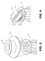
- FIG. 4 shows insert 110 partially inverted and positioned adjacent to opening 116 of main mold body 114.
- insert 110 incorporates a frusto-conical intermediate portion 118, with an opening 120 located at end 122 and a narrower opening 124 located at end 126.
- An annular flange 128 is located about end 122 and an annular flange 130 is located about end 126, with flange 128 extending farther radially from longitudinal axis 132 than flange 130.
- opening 116 when inserted into opening 116, contact between flange 130 of the insert and surface 140 of the main body portion prevents further movement of the insert into the opening. Since, opening 124 is smaller than upper opening 142 of the pourcup, a lip 144 is created. Lip 144 tends to direct molten metal that is poured into opening 120 of the insert into the pourcup. Additionally, the insert lines the passage between opening 116 of the main body portion and opening 142 of the pourcup, thereby forming a barrier between the molten metal (represented by arrow C) and the risers (e.g., riser 108).
Landscapes
- Engineering & Computer Science (AREA)
- Mechanical Engineering (AREA)
- Molds, Cores, And Manufacturing Methods Thereof (AREA)
Applications Claiming Priority (1)
| Application Number | Priority Date | Filing Date | Title |
|---|---|---|---|
| US12/032,839 US7882885B2 (en) | 2008-02-18 | 2008-02-18 | Systems and methods for reducing the potential for riser backfilling during investment casting |
Publications (2)
| Publication Number | Publication Date |
|---|---|
| EP2092997A1 true EP2092997A1 (de) | 2009-08-26 |
| EP2092997B1 EP2092997B1 (de) | 2014-07-30 |
Family
ID=40548744
Family Applications (1)
| Application Number | Title | Priority Date | Filing Date |
|---|---|---|---|
| EP09250417.4A Ceased EP2092997B1 (de) | 2008-02-18 | 2009-02-18 | Systeme und Verfahren zur Verringerung der Steigerverfüllung während des Feingiessens |
Country Status (2)
| Country | Link |
|---|---|
| US (1) | US7882885B2 (de) |
| EP (1) | EP2092997B1 (de) |
Cited By (2)
| Publication number | Priority date | Publication date | Assignee | Title |
|---|---|---|---|---|
| EP3479925A3 (de) * | 2012-12-14 | 2019-08-14 | United Technologies Corporation | Mehrschüssiges giessen |
| FR3129855A1 (fr) * | 2021-12-07 | 2023-06-09 | Safran Aircraft Engines | Moule de fabrication d'une pièce en matériau éliminable |
Families Citing this family (5)
| Publication number | Priority date | Publication date | Assignee | Title |
|---|---|---|---|---|
| EP3074159A4 (de) * | 2013-11-27 | 2017-08-02 | United Technologies Corporation | Verfahren und vorrichtung zur herstellung einer gussstruktur aus mehreren legierungen |
| US10493523B1 (en) * | 2016-02-04 | 2019-12-03 | Williams International Co., L.L.C. | Method of producing a cast component |
| CN107377883B (zh) * | 2017-09-09 | 2023-08-11 | 曲阜市华龙铸造材料有限公司 | 一种冒口自动加工生产装置 |
| WO2020081064A1 (en) * | 2018-10-16 | 2020-04-23 | General Electric Company | Directional solidification casting assembly and method |
| CN115740362B (zh) * | 2022-09-05 | 2026-02-17 | 贵州安吉航空精密铸造有限责任公司 | 一种熔模铸造方法 |
Citations (3)
| Publication number | Priority date | Publication date | Assignee | Title |
|---|---|---|---|---|
| US4300617A (en) | 1979-08-16 | 1981-11-17 | Precision Metalsmiths, Inc. | Pattern assemblies |
| EP0099687A1 (de) * | 1982-07-03 | 1984-02-01 | ROLLS-ROYCE plc | Eine Formanordnung für das Giessen von Metall-Gegenständen und ein Verfahren zur Herstellung derselben |
| US7231955B1 (en) | 2006-01-30 | 2007-06-19 | United Technologies Corporation | Investment casting mold design and method for investment casting using the same |
Family Cites Families (9)
| Publication number | Priority date | Publication date | Assignee | Title |
|---|---|---|---|---|
| GB2028928B (en) * | 1978-08-17 | 1982-08-25 | Ross Royce Ltd | Aerofoil blade for a gas turbine engine |
| US6350404B1 (en) * | 2000-06-13 | 2002-02-26 | Honeywell International, Inc. | Method for producing a ceramic part with an internal structure |
| US6637500B2 (en) * | 2001-10-24 | 2003-10-28 | United Technologies Corporation | Cores for use in precision investment casting |
| US6668906B2 (en) * | 2002-04-29 | 2003-12-30 | United Technologies Corporation | Shaped core for cast cooling passages and enhanced part definition |
| GB0226559D0 (en) * | 2002-11-14 | 2002-12-18 | Rolls Royce Plc | Investment moulding process and apparatus |
| US6929054B2 (en) * | 2003-12-19 | 2005-08-16 | United Technologies Corporation | Investment casting cores |
| US7134475B2 (en) * | 2004-10-29 | 2006-11-14 | United Technologies Corporation | Investment casting cores and methods |
| US7093645B2 (en) * | 2004-12-20 | 2006-08-22 | Howmet Research Corporation | Ceramic casting core and method |
| US7185695B1 (en) * | 2005-09-01 | 2007-03-06 | United Technologies Corporation | Investment casting pattern manufacture |
-
2008
- 2008-02-18 US US12/032,839 patent/US7882885B2/en not_active Expired - Fee Related
-
2009
- 2009-02-18 EP EP09250417.4A patent/EP2092997B1/de not_active Ceased
Patent Citations (3)
| Publication number | Priority date | Publication date | Assignee | Title |
|---|---|---|---|---|
| US4300617A (en) | 1979-08-16 | 1981-11-17 | Precision Metalsmiths, Inc. | Pattern assemblies |
| EP0099687A1 (de) * | 1982-07-03 | 1984-02-01 | ROLLS-ROYCE plc | Eine Formanordnung für das Giessen von Metall-Gegenständen und ein Verfahren zur Herstellung derselben |
| US7231955B1 (en) | 2006-01-30 | 2007-06-19 | United Technologies Corporation | Investment casting mold design and method for investment casting using the same |
Cited By (4)
| Publication number | Priority date | Publication date | Assignee | Title |
|---|---|---|---|---|
| EP3479925A3 (de) * | 2012-12-14 | 2019-08-14 | United Technologies Corporation | Mehrschüssiges giessen |
| US10456830B2 (en) | 2012-12-14 | 2019-10-29 | United Technologies Corporation | Multi-shot casting |
| US10576537B2 (en) | 2012-12-14 | 2020-03-03 | United Technologies Corporation | Multi-shot casting |
| FR3129855A1 (fr) * | 2021-12-07 | 2023-06-09 | Safran Aircraft Engines | Moule de fabrication d'une pièce en matériau éliminable |
Also Published As
| Publication number | Publication date |
|---|---|
| US7882885B2 (en) | 2011-02-08 |
| US20090205800A1 (en) | 2009-08-20 |
| EP2092997B1 (de) | 2014-07-30 |
Similar Documents
| Publication | Publication Date | Title |
|---|---|---|
| EP2092997B1 (de) | Systeme und Verfahren zur Verringerung der Steigerverfüllung während des Feingiessens | |
| US7231955B1 (en) | Investment casting mold design and method for investment casting using the same | |
| US7731481B2 (en) | Airfoil cooling with staggered refractory metal core microcircuits | |
| US8066052B2 (en) | Cooled wall thickness control | |
| US10421120B2 (en) | Metal casting apparatus, cast work piece and method therefor | |
| JP6965353B2 (ja) | 成形部品の独立したハンドリングのためのアクセサリを得るためのクラスタモデル及びシェル並びにこれに関連する方法 | |
| US7918265B2 (en) | Method and apparatus for as-cast seal on turbine blades | |
| EP1930097A1 (de) | Giesskern zur Verwendung in einer Giessform | |
| EP2223755A1 (de) | Giessverfahren | |
| US9616489B2 (en) | Casting pattern | |
| CN104439068B (zh) | 一种含有凸耳孔的凸耳合金零件的制作工艺 | |
| US10576535B2 (en) | Mold for fabricating a monocrystalline blade by casting, a fabrication installation and method using the mold | |
| CN108698117B (zh) | 一种形成涡轮叶片的除尘孔的方法及相关的陶瓷芯 | |
| EP3825031A1 (de) | Turbinenschaufelgiessen mit strontium-kern | |
| US20140110077A1 (en) | Casting Process and Apparatus | |
| US7958860B2 (en) | Crankcase, oil channel mold core for producing a crankcase and process for producing a crankcase | |
| US11878338B2 (en) | Mould for manufacturing a component by pouring metal and epitaxial growth, and associated manufacturing method | |
| CN115298357B (zh) | 对具有多孔陶瓷芯的铸造金属部件进行化学清洗的方法 | |
| CN104271288B (zh) | 铸造方法和铸造模具 | |
| US20220388056A1 (en) | Effective leaching of alumina-based casting cores | |
| US20180111186A1 (en) | Method and System for Casting Metal Using a Riser Sleeve with an Integral Mold Cavity Vent | |
| JP2010105023A (ja) | 減圧吸引鋳造方法 |
Legal Events
| Date | Code | Title | Description |
|---|---|---|---|
| PUAI | Public reference made under article 153(3) epc to a published international application that has entered the european phase |
Free format text: ORIGINAL CODE: 0009012 |
|
| AK | Designated contracting states |
Kind code of ref document: A1 Designated state(s): AT BE BG CH CY CZ DE DK EE ES FI FR GB GR HR HU IE IS IT LI LT LU LV MC MK MT NL NO PL PT RO SE SI SK TR |
|
| AX | Request for extension of the european patent |
Extension state: AL BA RS |
|
| 17P | Request for examination filed |
Effective date: 20091130 |
|
| AKX | Designation fees paid |
Designated state(s): DE GB |
|
| 17Q | First examination report despatched |
Effective date: 20100629 |
|
| GRAP | Despatch of communication of intention to grant a patent |
Free format text: ORIGINAL CODE: EPIDOSNIGR1 |
|
| INTG | Intention to grant announced |
Effective date: 20140422 |
|
| GRAS | Grant fee paid |
Free format text: ORIGINAL CODE: EPIDOSNIGR3 |
|
| GRAA | (expected) grant |
Free format text: ORIGINAL CODE: 0009210 |
|
| AK | Designated contracting states |
Kind code of ref document: B1 Designated state(s): DE GB |
|
| REG | Reference to a national code |
Ref country code: GB Ref legal event code: FG4D |
|
| REG | Reference to a national code |
Ref country code: DE Ref legal event code: R096 Ref document number: 602009025627 Country of ref document: DE Effective date: 20140911 |
|
| REG | Reference to a national code |
Ref country code: DE Ref legal event code: R097 Ref document number: 602009025627 Country of ref document: DE |
|
| PLBE | No opposition filed within time limit |
Free format text: ORIGINAL CODE: 0009261 |
|
| STAA | Information on the status of an ep patent application or granted ep patent |
Free format text: STATUS: NO OPPOSITION FILED WITHIN TIME LIMIT |
|
| 26N | No opposition filed |
Effective date: 20150504 |
|
| REG | Reference to a national code |
Ref country code: DE Ref legal event code: R082 Ref document number: 602009025627 Country of ref document: DE Representative=s name: SCHMITT-NILSON SCHRAUD WAIBEL WOHLFROM PATENTA, DE |
|
| REG | Reference to a national code |
Ref country code: DE Ref legal event code: R082 Ref document number: 602009025627 Country of ref document: DE Representative=s name: SCHMITT-NILSON SCHRAUD WAIBEL WOHLFROM PATENTA, DE Ref country code: DE Ref legal event code: R081 Ref document number: 602009025627 Country of ref document: DE Owner name: UNITED TECHNOLOGIES CORP. (N.D.GES.D. STAATES , US Free format text: FORMER OWNER: UNITED TECHNOLOGIES CORP., HARTFORD, CONN., US |
|
| PGFP | Annual fee paid to national office [announced via postgrant information from national office to epo] |
Ref country code: GB Payment date: 20220124 Year of fee payment: 14 Ref country code: DE Payment date: 20220119 Year of fee payment: 14 |
|
| REG | Reference to a national code |
Ref country code: DE Ref legal event code: R081 Ref document number: 602009025627 Country of ref document: DE Owner name: RAYTHEON TECHNOLOGIES CORPORATION (N.D.GES.D.S, US Free format text: FORMER OWNER: UNITED TECHNOLOGIES CORP. (N.D.GES.D. STAATES DELAWARE), FARMINGTON, CONN., US |
|
| REG | Reference to a national code |
Ref country code: DE Ref legal event code: R119 Ref document number: 602009025627 Country of ref document: DE |
|
| GBPC | Gb: european patent ceased through non-payment of renewal fee |
Effective date: 20230218 |
|
| PG25 | Lapsed in a contracting state [announced via postgrant information from national office to epo] |
Ref country code: GB Free format text: LAPSE BECAUSE OF NON-PAYMENT OF DUE FEES Effective date: 20230218 |
|
| PG25 | Lapsed in a contracting state [announced via postgrant information from national office to epo] |
Ref country code: GB Free format text: LAPSE BECAUSE OF NON-PAYMENT OF DUE FEES Effective date: 20230218 Ref country code: DE Free format text: LAPSE BECAUSE OF NON-PAYMENT OF DUE FEES Effective date: 20230901 |