EP2093024A1 - Dispositif électro-hydraulique avec contrôle électronique pour déformer des écrous à river - Google Patents
Dispositif électro-hydraulique avec contrôle électronique pour déformer des écrous à river Download PDFInfo
- Publication number
- EP2093024A1 EP2093024A1 EP08101965A EP08101965A EP2093024A1 EP 2093024 A1 EP2093024 A1 EP 2093024A1 EP 08101965 A EP08101965 A EP 08101965A EP 08101965 A EP08101965 A EP 08101965A EP 2093024 A1 EP2093024 A1 EP 2093024A1
- Authority
- EP
- European Patent Office
- Prior art keywords
- micro
- motor
- rod
- rivet
- switch
- Prior art date
- Legal status (The legal status is an assumption and is not a legal conclusion. Google has not performed a legal analysis and makes no representation as to the accuracy of the status listed.)
- Granted
Links
Images




Classifications
-
- B—PERFORMING OPERATIONS; TRANSPORTING
- B21—MECHANICAL METAL-WORKING WITHOUT ESSENTIALLY REMOVING MATERIAL; PUNCHING METAL
- B21J—FORGING; HAMMERING; PRESSING METAL; RIVETING; FORGE FURNACES
- B21J15/00—Riveting
- B21J15/10—Riveting machines
- B21J15/16—Drives for riveting machines; Transmission means therefor
- B21J15/20—Drives for riveting machines; Transmission means therefor operated by hydraulic or liquid pressure
-
- B—PERFORMING OPERATIONS; TRANSPORTING
- B21—MECHANICAL METAL-WORKING WITHOUT ESSENTIALLY REMOVING MATERIAL; PUNCHING METAL
- B21J—FORGING; HAMMERING; PRESSING METAL; RIVETING; FORGE FURNACES
- B21J15/00—Riveting
- B21J15/10—Riveting machines
- B21J15/16—Drives for riveting machines; Transmission means therefor
- B21J15/26—Drives for riveting machines; Transmission means therefor operated by rotary drive, e.g. by electric motor
-
- B—PERFORMING OPERATIONS; TRANSPORTING
- B25—HAND TOOLS; PORTABLE POWER-DRIVEN TOOLS; MANIPULATORS
- B25B—TOOLS OR BENCH DEVICES NOT OTHERWISE PROVIDED FOR, FOR FASTENING, CONNECTING, DISENGAGING, OR HOLDING
- B25B27/00—Hand tools, specially adapted for fitting together or separating parts or objects whether or not involving some deformation, not otherwise provided for
- B25B27/0007—Tools for fixing internally screw-threaded tubular fasteners
- B25B27/0014—Tools for fixing internally screw-threaded tubular fasteners motor-driven
-
- Y—GENERAL TAGGING OF NEW TECHNOLOGICAL DEVELOPMENTS; GENERAL TAGGING OF CROSS-SECTIONAL TECHNOLOGIES SPANNING OVER SEVERAL SECTIONS OF THE IPC; TECHNICAL SUBJECTS COVERED BY FORMER USPC CROSS-REFERENCE ART COLLECTIONS [XRACs] AND DIGESTS
- Y10—TECHNICAL SUBJECTS COVERED BY FORMER USPC
- Y10T—TECHNICAL SUBJECTS COVERED BY FORMER US CLASSIFICATION
- Y10T29/00—Metal working
- Y10T29/53—Means to assemble or disassemble
- Y10T29/53709—Overedge assembling means
- Y10T29/53717—Annular work
- Y10T29/53726—Annular work with second workpiece inside annular work one workpiece moved to shape the other
- Y10T29/5373—Annular work with second workpiece inside annular work one workpiece moved to shape the other comprising driver for snap-off-mandrel fastener; e.g., Pop [TM] riveter
- Y10T29/53739—Pneumatic- or fluid-actuated tool
- Y10T29/53743—Liquid
Definitions
- the invention relates to the technical sector of riveting pistols, with special reference to servo-assisted pistols, used for rivets having a cylindrical shape, a partially-threaded axial hole, an abutment collar at a head thereof and a specially-weakened portion at which the plastic deformation will occur.
- the rivets are destined to join two walls stably, for example in place of spot-welding, or for constituting a threaded anchoring bush of an adequate sturdiness, for structures made of too-soft or too-thin materials for fashioning sufficiently-resistant threads.
- the above-described rivets can be of considerable dimensions, and for their application it is necessary to avail of the necessary equipment, which must be able to exert thereon a high compression force.
- a known-type riveting pistol constructed by the same applicant in accordance with an Italian patent application for industrial invention no. BO2007A000311 , comprises a body and a grip wherein are housed:
- the pistol 100 further comprises an emergency button control, not illustrated in detail but preferably arranged with a position and/or conformation protected from accidental activation, associated to the electric circuit 6 and destined to activate the first micro-switch 1 such that the rod 2 rotates to the left, in a way which will be described herein below.
- an emergency button control not illustrated in detail but preferably arranged with a position and/or conformation protected from accidental activation, associated to the electric circuit 6 and destined to activate the first micro-switch 1 such that the rod 2 rotates to the left, in a way which will be described herein below.
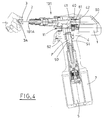
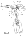
- the first transmission organs 11 are constituted, for example, by a plurality of gears also functioning as speed reducer; preferably these organs 11 cause the micro-motor 1 and the rod 2 to rotate in a same direction ( figures 2 and 3 ).
- the second transmission organs 52 are constituted, for example, by an epicyclical gear reducer.
- the second micro-switch 62 is activated and the control unit 60 starts up the automatic operating cycle of the pistol 100 ( figure 6 ).
- the second micro-motor 5 is then activated in the suitable direction, in order to determine the outward run of the piston 50 in the cylinder 51, with a consequent increase in the pressure of the hydraulic fluid F into the chamber 41 of the cursor 40 ( figure 7 ).
- the piston 50 continues to rise, while the pressurised fluid F overcomes the resistance of the contrast spring 42 and pushes the cursor 40 to retreat, together with the associated threaded rod 2.
- the translation continues, causing a progressive compression of the rivet 3 which deforms towards the outside, in the weakened portion, to define an annular edge 3C adhering to the surface of the wall P opposite the surface on which the collar 3B is resting, thus determining a blocking of the rivet 3 ( figure 8 ).
- the increase in the pressure in the hydraulic system 4 increases the resistance to rising of the piston 50, which leads to a proportional increase in the absorption of power on the part of the second micro-motor 5.
- the value of this absorption is constantly monitored by the control unit 60, since the force exerted on the rod 2 to deform the rivet 3 is calculated in relation thereto, by means of suitable parameters.
- the maximum peak of absorption the second micro-switch 5 has to reach is calculated and the relative datum is stored in the control unit 60.
- the control unit 60 inverts the rotation of the second micro-motor 5, with consequent inversion of the movement of the piston 50 ( figure 9 ).
- the above leads to a sharp drop in hydraulic fluid pressure F, with a consequent interruption of the retraction of the cursor-rod group and thus of the stressed on the rivet 3.
- the contrast spring 42 While the piston 50 proceeds in its descent, due to the action of the second micro-motor 5, the contrast spring 42 newly prevails on the force determined by the fluid pressure F and advances the cursor 40 and the rod 2.
- the control unit 60 in a suitable phase relation with the descent of the piston 50, starts up the first micro-motor 1 too, setting the threaded rod 2 in leftwise rotation so that it unscrews from the rivet 3 which by now is blocked to the wall P ( figure 10 ).
- the second micro-motor 5 is maintained in motion until the piston 50 reaches the lowered start position, after which it is automatically deactivated by the control unit 60 (see figure 10 once more); the signal which attests to the reaching of the position can be given by an end-run sensor (not illustrated), or by the increase of absorption of the micro-motor 5 consequent upon the intercepting of a mechanical end-run stop 53 which is integral with the piston 50.
- the foreseen functioning program is completed ( figure 11 ).
- the pistol 100 is newly in the condition described with reference to figure 4 , with the control unit 60 predisposed for a new cycle.
- a particularly able operator therefore, can optimally synchronise the disengagement of the rod 2 with the halting of the micro-motor 1, such as to render the pistol 100 immediately ready for another rivet 3, previously positioned on the wall P.
- the unscrewing can be completed by pressing the emergency command, in order to reactivate the micro-motor 1 with a further left-wise rotation of the rod 2.
- the pistol 100 does not minimally suffer from any manoeuvring error which might be committed if, following an early release of the trigger 63, pressure is newly placed thereon.
- the control logic of the control unit 60 can be programmed to continue the interrupted cycle if, for example, release occurs during the stage of deformation of the rivet 3.
- the pistol repeats the automatic traction cycle on the rod 2 without causing undesired stress on the rivet 3 applied, as on reaching the preceding maximum fluid pressure F, the control unit 60 interrupts the action and starts unscrewing, so that the only drawback that obtains is a slight waste of time.
- Other embodiments of the electro-hydraulic pistol device are envisaged, apart from the one illustrated and described herein above.
- the batteries 7 and possibly also the control unit 60 can be housed in a module which is external of the body of the pistol; this is to contain the weight and size of the pistol, making it easier to use.
- the batteries are eliminated and electrical energy is sourced from a network, with the interposing of a suitable transformer/rectifier, with the aim of obtaining unlimited working autonomy, together (in this case too) with a considerable reduction in weight.
- the constructional characteristics of the two above-mentioned embodiments are combined, thus providing a module which is external of the body of the pistol which contains, apart from the batteries and the control unit, the transformer/rectifier for network-sourced power and possibly a device for recharging the batteries. From the above it can be understood how the electro-hydraulic pistol device fully reaches the set aims, in particular for obtaining a functioning logic which is entirely similar to that of the known-type pistol cited in the preamble hereto, without there being any need for supply of compressed air.
Landscapes
- Mechanical Engineering (AREA)
- Engineering & Computer Science (AREA)
- Portable Nailing Machines And Staplers (AREA)
- Fluid-Pressure Circuits (AREA)
- Actuator (AREA)
- Manufacturing Of Electrical Connectors (AREA)
- Regulating Braking Force (AREA)
- Clamps And Clips (AREA)
- Gripping Jigs, Holding Jigs, And Positioning Jigs (AREA)
- Manipulator (AREA)
- Connection Of Plates (AREA)
- Servomotors (AREA)
- Hand Tools For Fitting Together And Separating, Or Other Hand Tools (AREA)
- Surgical Instruments (AREA)
Applications Claiming Priority (1)
| Application Number | Priority Date | Filing Date | Title |
|---|---|---|---|
| IT000117A ITBO20080117A1 (it) | 2008-02-21 | 2008-02-21 | Dispositivo elettro-idraulico a pistola con controllo elettronico per la deformazione di elementi di fissaggio |
Publications (2)
| Publication Number | Publication Date |
|---|---|
| EP2093024A1 true EP2093024A1 (fr) | 2009-08-26 |
| EP2093024B1 EP2093024B1 (fr) | 2010-09-22 |
Family
ID=40291438
Family Applications (1)
| Application Number | Title | Priority Date | Filing Date |
|---|---|---|---|
| EP08101965A Active EP2093024B1 (fr) | 2008-02-21 | 2008-02-25 | Dispositif électro-hydraulique avec contrôle électronique pour déformer des écrous à river |
Country Status (8)
| Country | Link |
|---|---|
| US (1) | US20110271504A1 (fr) |
| EP (1) | EP2093024B1 (fr) |
| AT (1) | ATE482055T1 (fr) |
| BR (1) | BRPI0907795B1 (fr) |
| DE (1) | DE602008002698D1 (fr) |
| ES (1) | ES2353468T3 (fr) |
| IT (1) | ITBO20080117A1 (fr) |
| WO (1) | WO2009103695A1 (fr) |
Cited By (8)
| Publication number | Priority date | Publication date | Assignee | Title |
|---|---|---|---|---|
| WO2011026944A1 (fr) * | 2009-09-04 | 2011-03-10 | Böllhoff Verbindungstechnik GmbH | Entraînement hydraulique à moteur électrique et procédé pour fournir une pression et/ou un volume hydrauliques définis |
| ITBO20120276A1 (it) * | 2012-05-21 | 2013-11-22 | Ober S P A | Dispositivo elettro-idraulico a pistola con controllo elettronico per la deformazione di elementi di fissaggio |
| WO2014195189A1 (fr) * | 2013-06-04 | 2014-12-11 | VVG-Befestigungstechnik GmbH & Co. KG | Appareil de rivetage |
| EP3067157A1 (fr) | 2015-03-11 | 2016-09-14 | OBER S.p.A. | Système de couplage/découplage d'un tirant fileté vers/depuis un siège de tirant dans un pistolet pour déformer des éléments de fixation et pistolet avec le système |
| US20200070327A1 (en) * | 2018-09-05 | 2020-03-05 | Milwaukee Electric Tool Corporation | Blind rivet nut-setting tool |
| EP4008482A1 (fr) * | 2020-12-07 | 2022-06-08 | Dubuis et Cie | Outil d'assemblage pour assembler un élément déformable sur une pièce à usiner |
| EP4371681A1 (fr) | 2022-11-17 | 2024-05-22 | Bollhoff Otalu S.A.S. | Dispositif de pose pour écrou à rivet aveugle |
| US12453999B2 (en) | 2021-07-28 | 2025-10-28 | Milwaukee Electric Tool Corporation | Blind rivet nut-setting tool |
Families Citing this family (12)
| Publication number | Priority date | Publication date | Assignee | Title |
|---|---|---|---|---|
| US8205779B2 (en) | 2009-07-23 | 2012-06-26 | Tyco Healthcare Group Lp | Surgical stapler with tactile feedback system |
| JP5674691B2 (ja) | 2012-02-23 | 2015-02-25 | 株式会社ロブテックス | 電動リベッター |
| EP2786843B1 (fr) * | 2013-04-02 | 2019-09-25 | Dubuis et Cie S.A.S. | Outil de sertissage alimenté par batterie |
| TWI477331B (zh) * | 2013-08-09 | 2015-03-21 | Tranmax Machinery Co Ltd | Electromotive pull nail gun with pre - tensioned nail and its operation method |
| CN207915402U (zh) | 2018-02-13 | 2018-09-28 | 米沃奇电动工具公司 | 用于铆钉设置工具的鼻夹组 |
| JP7187339B2 (ja) * | 2019-01-30 | 2022-12-12 | ポップリベット・ファスナー株式会社 | ブラインドナット締結装置 |
| WO2021247876A1 (fr) | 2020-06-03 | 2021-12-09 | Milwaukee Electric Tool Corporation | Outil de rivetage |
| IT202100010556A1 (it) * | 2021-04-27 | 2022-10-27 | Ober S P A | Attrezzatura portatile |
| CN223507129U (zh) | 2022-07-08 | 2025-11-04 | 米沃奇电动工具公司 | 动力式紧固件驱动器 |
| US12343785B2 (en) * | 2023-04-11 | 2025-07-01 | Techway Industrial Co., Ltd. | Power tool |
| EP4653143A1 (fr) | 2024-05-21 | 2025-11-26 | Bollhof Otalu SAS | Dispositif de pose et procédé de pose d'écrou à rivet aveugle |
| AU2024339206B1 (en) * | 2024-12-05 | 2025-07-31 | Meishan Crrc Fastening System Co., Ltd. | Electro-hydraulic Riveting Tool |
Citations (2)
| Publication number | Priority date | Publication date | Assignee | Title |
|---|---|---|---|---|
| FR2779670A1 (fr) * | 1998-06-15 | 1999-12-17 | Jean Claude Joux | Appareil electroportatif pour la pose des ecrous a sertir ou le sertissage des rivets aveugles a rupture de tige |
| WO2008132576A2 (fr) * | 2007-04-27 | 2008-11-06 | Ober S.P.A. | Riveteuse pneumo-hydraulique |
Family Cites Families (6)
| Publication number | Priority date | Publication date | Assignee | Title |
|---|---|---|---|---|
| US2753072A (en) * | 1952-08-12 | 1956-07-03 | Thor Power Tool Co | Tool for installing tubular rivets |
| JPH0475882A (ja) * | 1990-07-13 | 1992-03-10 | Makita Corp | 電動工具 |
| DE4126602A1 (de) * | 1991-08-12 | 1993-02-18 | Gesipa Blindniettechnik | Blindnietgeraet |
| DE19818757A1 (de) * | 1998-04-27 | 1999-11-04 | Honsel M H Beteiligungs Gmbh | Nietsetzgerät |
| DE19818756A1 (de) * | 1998-04-27 | 1999-11-04 | Honsel M H Beteiligungs Gmbh | Nietsetzgerät |
| GB9923266D0 (en) * | 1999-10-02 | 1999-12-08 | Textron Fastening Syst Ltd | Riveting apparatus |
-
2008
- 2008-02-21 IT IT000117A patent/ITBO20080117A1/it unknown
- 2008-02-25 DE DE602008002698T patent/DE602008002698D1/de active Active
- 2008-02-25 ES ES08101965T patent/ES2353468T3/es active Active
- 2008-02-25 EP EP08101965A patent/EP2093024B1/fr active Active
- 2008-02-25 AT AT08101965T patent/ATE482055T1/de not_active IP Right Cessation
-
2009
- 2009-02-17 BR BRPI0907795A patent/BRPI0907795B1/pt active IP Right Grant
- 2009-02-17 WO PCT/EP2009/051839 patent/WO2009103695A1/fr not_active Ceased
- 2009-07-16 US US12/866,846 patent/US20110271504A1/en not_active Abandoned
Patent Citations (2)
| Publication number | Priority date | Publication date | Assignee | Title |
|---|---|---|---|---|
| FR2779670A1 (fr) * | 1998-06-15 | 1999-12-17 | Jean Claude Joux | Appareil electroportatif pour la pose des ecrous a sertir ou le sertissage des rivets aveugles a rupture de tige |
| WO2008132576A2 (fr) * | 2007-04-27 | 2008-11-06 | Ober S.P.A. | Riveteuse pneumo-hydraulique |
Cited By (15)
| Publication number | Priority date | Publication date | Assignee | Title |
|---|---|---|---|---|
| WO2011026944A1 (fr) * | 2009-09-04 | 2011-03-10 | Böllhoff Verbindungstechnik GmbH | Entraînement hydraulique à moteur électrique et procédé pour fournir une pression et/ou un volume hydrauliques définis |
| ITBO20120276A1 (it) * | 2012-05-21 | 2013-11-22 | Ober S P A | Dispositivo elettro-idraulico a pistola con controllo elettronico per la deformazione di elementi di fissaggio |
| WO2014195189A1 (fr) * | 2013-06-04 | 2014-12-11 | VVG-Befestigungstechnik GmbH & Co. KG | Appareil de rivetage |
| US10112232B2 (en) | 2013-06-04 | 2018-10-30 | VVG-Befestigungstechnik GmbH & Co. KG | Riveting device |
| EP3067157A1 (fr) | 2015-03-11 | 2016-09-14 | OBER S.p.A. | Système de couplage/découplage d'un tirant fileté vers/depuis un siège de tirant dans un pistolet pour déformer des éléments de fixation et pistolet avec le système |
| EP3674037A1 (fr) * | 2018-09-05 | 2020-07-01 | Milwaukee Electric Tool Corporation | Outil de réglage d'écrou à rivet aveugle |
| US20200070327A1 (en) * | 2018-09-05 | 2020-03-05 | Milwaukee Electric Tool Corporation | Blind rivet nut-setting tool |
| US11673243B2 (en) * | 2018-09-05 | 2023-06-13 | Milwaukee Electric Tool Corporation | Blind rivet nut-setting tool |
| US20230271307A1 (en) * | 2018-09-05 | 2023-08-31 | Milwaukee Electric Tool Corporation | Blind rivet nut-setting tool |
| US12194603B2 (en) * | 2018-09-05 | 2025-01-14 | Milwaukee Electric Tool Corporation | Blind rivet nut-setting tool |
| US20250114925A1 (en) * | 2018-09-05 | 2025-04-10 | Milwaukee Electric Tool Corporation | Blind rivet nut-setting tool |
| EP4008482A1 (fr) * | 2020-12-07 | 2022-06-08 | Dubuis et Cie | Outil d'assemblage pour assembler un élément déformable sur une pièce à usiner |
| US12453999B2 (en) | 2021-07-28 | 2025-10-28 | Milwaukee Electric Tool Corporation | Blind rivet nut-setting tool |
| EP4371681A1 (fr) | 2022-11-17 | 2024-05-22 | Bollhoff Otalu S.A.S. | Dispositif de pose pour écrou à rivet aveugle |
| WO2024104644A1 (fr) | 2022-11-17 | 2024-05-23 | Bollhoff Otalu Sas | Dispositif de pose d'un écrou de rivet aveugle |
Also Published As
| Publication number | Publication date |
|---|---|
| US20110271504A1 (en) | 2011-11-10 |
| WO2009103695A1 (fr) | 2009-08-27 |
| EP2093024B1 (fr) | 2010-09-22 |
| BRPI0907795B1 (pt) | 2019-12-17 |
| ES2353468T3 (es) | 2011-03-02 |
| BRPI0907795A2 (pt) | 2015-07-14 |
| ITBO20080117A1 (it) | 2009-08-22 |
| ATE482055T1 (de) | 2010-10-15 |
| DE602008002698D1 (de) | 2010-11-04 |
Similar Documents
| Publication | Publication Date | Title |
|---|---|---|
| EP2093024B1 (fr) | Dispositif électro-hydraulique avec contrôle électronique pour déformer des écrous à river | |
| EP3213881B1 (fr) | Outil de coupe ou de compression hydrodynamique | |
| EP2786843B1 (fr) | Outil de sertissage alimenté par batterie | |
| EP3166755B1 (fr) | Procédé d'exploitation d'un outil de compression hydrodynamique et outil de compression hydrodynamique | |
| US10589341B2 (en) | Multi-step joining device and joining method therefor | |
| US20190232481A1 (en) | Power Tool | |
| US10265758B2 (en) | Power tool | |
| US8074485B2 (en) | Tool head assemblies for pressing devices | |
| NO308941B1 (no) | Blindnaglemutter - setteapparat | |
| EP3590661B1 (fr) | Accessoire d'outil de rivetage et dispositif de rivetage | |
| AU773183B2 (en) | Riveting apparatus | |
| CN1951630B (zh) | 压靠组件 | |
| WO1999004917A1 (fr) | Pistolet a riveter pneumatico-hydraulique | |
| EP3674037B1 (fr) | Outil de réglage d'écrou à rivet aveugle | |
| EP2150378B1 (fr) | Riveteuse pneumo-hydraulique | |
| US9360028B2 (en) | Hydraulic drive and hydraulically operable working tool | |
| US10421164B2 (en) | Device and method for transmitting a mechanical force for driving a pressing device for press fittings | |
| US20240191728A1 (en) | Hydraulic Pump | |
| CN119486826A (zh) | 铆接装置、芯轴容纳件以及铆接装置的组装方法 | |
| EP2834027A1 (fr) | Outil d'installation d'élément de fixation |
Legal Events
| Date | Code | Title | Description |
|---|---|---|---|
| PUAI | Public reference made under article 153(3) epc to a published international application that has entered the european phase |
Free format text: ORIGINAL CODE: 0009012 |
|
| AK | Designated contracting states |
Kind code of ref document: A1 Designated state(s): AT BE BG CH CY CZ DE DK EE ES FI FR GB GR HR HU IE IS IT LI LT LU LV MC MT NL NO PL PT RO SE SI SK TR |
|
| AX | Request for extension of the european patent |
Extension state: AL BA MK RS |
|
| 17P | Request for examination filed |
Effective date: 20100210 |
|
| GRAP | Despatch of communication of intention to grant a patent |
Free format text: ORIGINAL CODE: EPIDOSNIGR1 |
|
| AKX | Designation fees paid |
Designated state(s): AT BE BG CH CY CZ DE DK EE ES FI FR GB GR HR HU IE IS IT LI LT LU LV MC MT NL NO PL PT RO SE SI SK TR |
|
| GRAS | Grant fee paid |
Free format text: ORIGINAL CODE: EPIDOSNIGR3 |
|
| GRAA | (expected) grant |
Free format text: ORIGINAL CODE: 0009210 |
|
| AK | Designated contracting states |
Kind code of ref document: B1 Designated state(s): AT BE BG CH CY CZ DE DK EE ES FI FR GB GR HR HU IE IS IT LI LT LU LV MC MT NL NO PL PT RO SE SI SK TR |
|
| REG | Reference to a national code |
Ref country code: GB Ref legal event code: FG4D |
|
| REG | Reference to a national code |
Ref country code: CH Ref legal event code: EP |
|
| REG | Reference to a national code |
Ref country code: IE Ref legal event code: FG4D |
|
| REF | Corresponds to: |
Ref document number: 602008002698 Country of ref document: DE Date of ref document: 20101104 Kind code of ref document: P |
|
| PG25 | Lapsed in a contracting state [announced via postgrant information from national office to epo] |
Ref country code: AT Free format text: LAPSE BECAUSE OF FAILURE TO SUBMIT A TRANSLATION OF THE DESCRIPTION OR TO PAY THE FEE WITHIN THE PRESCRIBED TIME-LIMIT Effective date: 20100922 Ref country code: NO Free format text: LAPSE BECAUSE OF FAILURE TO SUBMIT A TRANSLATION OF THE DESCRIPTION OR TO PAY THE FEE WITHIN THE PRESCRIBED TIME-LIMIT Effective date: 20101222 Ref country code: FI Free format text: LAPSE BECAUSE OF FAILURE TO SUBMIT A TRANSLATION OF THE DESCRIPTION OR TO PAY THE FEE WITHIN THE PRESCRIBED TIME-LIMIT Effective date: 20100922 Ref country code: LT Free format text: LAPSE BECAUSE OF FAILURE TO SUBMIT A TRANSLATION OF THE DESCRIPTION OR TO PAY THE FEE WITHIN THE PRESCRIBED TIME-LIMIT Effective date: 20100922 |
|
| REG | Reference to a national code |
Ref country code: NL Ref legal event code: VDEP Effective date: 20100922 |
|
| LTIE | Lt: invalidation of european patent or patent extension |
Effective date: 20100922 |
|
| PG25 | Lapsed in a contracting state [announced via postgrant information from national office to epo] |
Ref country code: SI Free format text: LAPSE BECAUSE OF FAILURE TO SUBMIT A TRANSLATION OF THE DESCRIPTION OR TO PAY THE FEE WITHIN THE PRESCRIBED TIME-LIMIT Effective date: 20100922 Ref country code: HR Free format text: LAPSE BECAUSE OF FAILURE TO SUBMIT A TRANSLATION OF THE DESCRIPTION OR TO PAY THE FEE WITHIN THE PRESCRIBED TIME-LIMIT Effective date: 20100922 Ref country code: PL Free format text: LAPSE BECAUSE OF FAILURE TO SUBMIT A TRANSLATION OF THE DESCRIPTION OR TO PAY THE FEE WITHIN THE PRESCRIBED TIME-LIMIT Effective date: 20100922 |
|
| REG | Reference to a national code |
Ref country code: ES Ref legal event code: FG2A Effective date: 20110218 |
|
| PG25 | Lapsed in a contracting state [announced via postgrant information from national office to epo] |
Ref country code: LV Free format text: LAPSE BECAUSE OF FAILURE TO SUBMIT A TRANSLATION OF THE DESCRIPTION OR TO PAY THE FEE WITHIN THE PRESCRIBED TIME-LIMIT Effective date: 20100922 Ref country code: SE Free format text: LAPSE BECAUSE OF FAILURE TO SUBMIT A TRANSLATION OF THE DESCRIPTION OR TO PAY THE FEE WITHIN THE PRESCRIBED TIME-LIMIT Effective date: 20100922 Ref country code: GR Free format text: LAPSE BECAUSE OF FAILURE TO SUBMIT A TRANSLATION OF THE DESCRIPTION OR TO PAY THE FEE WITHIN THE PRESCRIBED TIME-LIMIT Effective date: 20101223 |
|
| PG25 | Lapsed in a contracting state [announced via postgrant information from national office to epo] |
Ref country code: EE Free format text: LAPSE BECAUSE OF FAILURE TO SUBMIT A TRANSLATION OF THE DESCRIPTION OR TO PAY THE FEE WITHIN THE PRESCRIBED TIME-LIMIT Effective date: 20100922 Ref country code: CZ Free format text: LAPSE BECAUSE OF FAILURE TO SUBMIT A TRANSLATION OF THE DESCRIPTION OR TO PAY THE FEE WITHIN THE PRESCRIBED TIME-LIMIT Effective date: 20100922 Ref country code: RO Free format text: LAPSE BECAUSE OF FAILURE TO SUBMIT A TRANSLATION OF THE DESCRIPTION OR TO PAY THE FEE WITHIN THE PRESCRIBED TIME-LIMIT Effective date: 20100922 Ref country code: NL Free format text: LAPSE BECAUSE OF FAILURE TO SUBMIT A TRANSLATION OF THE DESCRIPTION OR TO PAY THE FEE WITHIN THE PRESCRIBED TIME-LIMIT Effective date: 20100922 Ref country code: SK Free format text: LAPSE BECAUSE OF FAILURE TO SUBMIT A TRANSLATION OF THE DESCRIPTION OR TO PAY THE FEE WITHIN THE PRESCRIBED TIME-LIMIT Effective date: 20100922 Ref country code: PT Free format text: LAPSE BECAUSE OF FAILURE TO SUBMIT A TRANSLATION OF THE DESCRIPTION OR TO PAY THE FEE WITHIN THE PRESCRIBED TIME-LIMIT Effective date: 20110124 Ref country code: IS Free format text: LAPSE BECAUSE OF FAILURE TO SUBMIT A TRANSLATION OF THE DESCRIPTION OR TO PAY THE FEE WITHIN THE PRESCRIBED TIME-LIMIT Effective date: 20110122 |
|
| PG25 | Lapsed in a contracting state [announced via postgrant information from national office to epo] |
Ref country code: BE Free format text: LAPSE BECAUSE OF FAILURE TO SUBMIT A TRANSLATION OF THE DESCRIPTION OR TO PAY THE FEE WITHIN THE PRESCRIBED TIME-LIMIT Effective date: 20100922 |
|
| PLBE | No opposition filed within time limit |
Free format text: ORIGINAL CODE: 0009261 |
|
| STAA | Information on the status of an ep patent application or granted ep patent |
Free format text: STATUS: NO OPPOSITION FILED WITHIN TIME LIMIT |
|
| 26N | No opposition filed |
Effective date: 20110623 |
|
| PG25 | Lapsed in a contracting state [announced via postgrant information from national office to epo] |
Ref country code: DK Free format text: LAPSE BECAUSE OF FAILURE TO SUBMIT A TRANSLATION OF THE DESCRIPTION OR TO PAY THE FEE WITHIN THE PRESCRIBED TIME-LIMIT Effective date: 20100922 |
|
| PG25 | Lapsed in a contracting state [announced via postgrant information from national office to epo] |
Ref country code: MC Free format text: LAPSE BECAUSE OF NON-PAYMENT OF DUE FEES Effective date: 20110228 |
|
| REG | Reference to a national code |
Ref country code: DE Ref legal event code: R097 Ref document number: 602008002698 Country of ref document: DE Effective date: 20110623 |
|
| REG | Reference to a national code |
Ref country code: IE Ref legal event code: MM4A |
|
| PG25 | Lapsed in a contracting state [announced via postgrant information from national office to epo] |
Ref country code: MT Free format text: LAPSE BECAUSE OF FAILURE TO SUBMIT A TRANSLATION OF THE DESCRIPTION OR TO PAY THE FEE WITHIN THE PRESCRIBED TIME-LIMIT Effective date: 20100922 |
|
| PG25 | Lapsed in a contracting state [announced via postgrant information from national office to epo] |
Ref country code: IE Free format text: LAPSE BECAUSE OF NON-PAYMENT OF DUE FEES Effective date: 20110225 |
|
| REG | Reference to a national code |
Ref country code: CH Ref legal event code: PL |
|
| PG25 | Lapsed in a contracting state [announced via postgrant information from national office to epo] |
Ref country code: LI Free format text: LAPSE BECAUSE OF NON-PAYMENT OF DUE FEES Effective date: 20120229 Ref country code: CH Free format text: LAPSE BECAUSE OF NON-PAYMENT OF DUE FEES Effective date: 20120229 |
|
| PG25 | Lapsed in a contracting state [announced via postgrant information from national office to epo] |
Ref country code: CY Free format text: LAPSE BECAUSE OF FAILURE TO SUBMIT A TRANSLATION OF THE DESCRIPTION OR TO PAY THE FEE WITHIN THE PRESCRIBED TIME-LIMIT Effective date: 20100922 Ref country code: LU Free format text: LAPSE BECAUSE OF NON-PAYMENT OF DUE FEES Effective date: 20110225 |
|
| PG25 | Lapsed in a contracting state [announced via postgrant information from national office to epo] |
Ref country code: BG Free format text: LAPSE BECAUSE OF FAILURE TO SUBMIT A TRANSLATION OF THE DESCRIPTION OR TO PAY THE FEE WITHIN THE PRESCRIBED TIME-LIMIT Effective date: 20101222 |
|
| PG25 | Lapsed in a contracting state [announced via postgrant information from national office to epo] |
Ref country code: HU Free format text: LAPSE BECAUSE OF FAILURE TO SUBMIT A TRANSLATION OF THE DESCRIPTION OR TO PAY THE FEE WITHIN THE PRESCRIBED TIME-LIMIT Effective date: 20100922 |
|
| REG | Reference to a national code |
Ref country code: FR Ref legal event code: PLFP Year of fee payment: 9 |
|
| REG | Reference to a national code |
Ref country code: FR Ref legal event code: PLFP Year of fee payment: 10 |
|
| REG | Reference to a national code |
Ref country code: FR Ref legal event code: PLFP Year of fee payment: 11 |
|
| PGFP | Annual fee paid to national office [announced via postgrant information from national office to epo] |
Ref country code: DE Payment date: 20250226 Year of fee payment: 18 |
|
| PGFP | Annual fee paid to national office [announced via postgrant information from national office to epo] |
Ref country code: ES Payment date: 20250303 Year of fee payment: 18 |
|
| PGFP | Annual fee paid to national office [announced via postgrant information from national office to epo] |
Ref country code: FR Payment date: 20250228 Year of fee payment: 18 |
|
| PGFP | Annual fee paid to national office [announced via postgrant information from national office to epo] |
Ref country code: IT Payment date: 20250221 Year of fee payment: 18 Ref country code: GB Payment date: 20250227 Year of fee payment: 18 |
|
| PGFP | Annual fee paid to national office [announced via postgrant information from national office to epo] |
Ref country code: TR Payment date: 20250317 Year of fee payment: 18 |