EP2093027A1 - Gelenkmechanismus und gelenkvorrichtung - Google Patents
Gelenkmechanismus und gelenkvorrichtung Download PDFInfo
- Publication number
- EP2093027A1 EP2093027A1 EP07859749A EP07859749A EP2093027A1 EP 2093027 A1 EP2093027 A1 EP 2093027A1 EP 07859749 A EP07859749 A EP 07859749A EP 07859749 A EP07859749 A EP 07859749A EP 2093027 A1 EP2093027 A1 EP 2093027A1
- Authority
- EP
- European Patent Office
- Prior art keywords
- link
- worm
- joint mechanism
- angle
- shaft
- Prior art date
- Legal status (The legal status is an assumption and is not a legal conclusion. Google has not performed a legal analysis and makes no representation as to the accuracy of the status listed.)
- Granted
Links
Images





Classifications
-
- B—PERFORMING OPERATIONS; TRANSPORTING
- B25—HAND TOOLS; PORTABLE POWER-DRIVEN TOOLS; MANIPULATORS
- B25J—MANIPULATORS; CHAMBERS PROVIDED WITH MANIPULATION DEVICES
- B25J15/00—Gripping heads and other end effectors
- B25J15/0009—Gripping heads and other end effectors comprising multi-articulated fingers, e.g. resembling a human hand
-
- B—PERFORMING OPERATIONS; TRANSPORTING
- B25—HAND TOOLS; PORTABLE POWER-DRIVEN TOOLS; MANIPULATORS
- B25J—MANIPULATORS; CHAMBERS PROVIDED WITH MANIPULATION DEVICES
- B25J9/00—Program-controlled manipulators
- B25J9/10—Program-controlled manipulators characterised by positioning means for manipulator elements
- B25J9/102—Gears specially adapted therefor, e.g. reduction gears
-
- F—MECHANICAL ENGINEERING; LIGHTING; HEATING; WEAPONS; BLASTING
- F16—ENGINEERING ELEMENTS AND UNITS; GENERAL MEASURES FOR PRODUCING AND MAINTAINING EFFECTIVE FUNCTIONING OF MACHINES OR INSTALLATIONS; THERMAL INSULATION IN GENERAL
- F16H—GEARING
- F16H1/00—Toothed gearings for conveying rotary motion
- F16H1/02—Toothed gearings for conveying rotary motion without gears having orbital motion
- F16H1/04—Toothed gearings for conveying rotary motion without gears having orbital motion involving only two intermeshing members
- F16H1/12—Toothed gearings for conveying rotary motion without gears having orbital motion involving only two intermeshing members with non-parallel axes
- F16H1/16—Toothed gearings for conveying rotary motion without gears having orbital motion involving only two intermeshing members with non-parallel axes comprising worm and worm-wheel
-
- Y—GENERAL TAGGING OF NEW TECHNOLOGICAL DEVELOPMENTS; GENERAL TAGGING OF CROSS-SECTIONAL TECHNOLOGIES SPANNING OVER SEVERAL SECTIONS OF THE IPC; TECHNICAL SUBJECTS COVERED BY FORMER USPC CROSS-REFERENCE ART COLLECTIONS [XRACs] AND DIGESTS
- Y10—TECHNICAL SUBJECTS COVERED BY FORMER USPC
- Y10T—TECHNICAL SUBJECTS COVERED BY FORMER US CLASSIFICATION
- Y10T74/00—Machine element or mechanism
- Y10T74/19—Gearing
- Y10T74/19637—Gearing with brake means for gearing
-
- Y—GENERAL TAGGING OF NEW TECHNOLOGICAL DEVELOPMENTS; GENERAL TAGGING OF CROSS-SECTIONAL TECHNOLOGIES SPANNING OVER SEVERAL SECTIONS OF THE IPC; TECHNICAL SUBJECTS COVERED BY FORMER USPC CROSS-REFERENCE ART COLLECTIONS [XRACs] AND DIGESTS
- Y10—TECHNICAL SUBJECTS COVERED BY FORMER USPC
- Y10T—TECHNICAL SUBJECTS COVERED BY FORMER US CLASSIFICATION
- Y10T74/00—Machine element or mechanism
- Y10T74/19—Gearing
- Y10T74/19642—Directly cooperating gears
- Y10T74/19698—Spiral
- Y10T74/19828—Worm
-
- Y—GENERAL TAGGING OF NEW TECHNOLOGICAL DEVELOPMENTS; GENERAL TAGGING OF CROSS-SECTIONAL TECHNOLOGIES SPANNING OVER SEVERAL SECTIONS OF THE IPC; TECHNICAL SUBJECTS COVERED BY FORMER USPC CROSS-REFERENCE ART COLLECTIONS [XRACs] AND DIGESTS
- Y10—TECHNICAL SUBJECTS COVERED BY FORMER USPC
- Y10T—TECHNICAL SUBJECTS COVERED BY FORMER US CLASSIFICATION
- Y10T74/00—Machine element or mechanism
- Y10T74/20—Control lever and linkage systems
- Y10T74/20207—Multiple controlling elements for single controlled element
- Y10T74/20305—Robotic arm
- Y10T74/20317—Robotic arm including electric motor
-
- Y—GENERAL TAGGING OF NEW TECHNOLOGICAL DEVELOPMENTS; GENERAL TAGGING OF CROSS-SECTIONAL TECHNOLOGIES SPANNING OVER SEVERAL SECTIONS OF THE IPC; TECHNICAL SUBJECTS COVERED BY FORMER USPC CROSS-REFERENCE ART COLLECTIONS [XRACs] AND DIGESTS
- Y10—TECHNICAL SUBJECTS COVERED BY FORMER USPC
- Y10T—TECHNICAL SUBJECTS COVERED BY FORMER US CLASSIFICATION
- Y10T74/00—Machine element or mechanism
- Y10T74/20—Control lever and linkage systems
- Y10T74/20207—Multiple controlling elements for single controlled element
- Y10T74/20305—Robotic arm
- Y10T74/20329—Joint between elements
Definitions
- a worm wheel 93 is rotated by a worm 92 mounted at a lead end of a motor 91.
- links 94 and 95 serving as a gripping finger are pivotally moved in e.g. a gripping direction. Even if a force to open up the link 95 is exerted on the link 95, there is no likelihood that the worm wheel 93 may be rotated in backward direction because of engagement with the worm 92. In this arrangement, the gripping mechanism is allowed to keep holding an article.
- the gripping mechanism shown in FIG. 22 has a sufficient degree of freedom for a gripping operation.
- the production cost may be increased.
- the number of drive sources may be increased, although an intended posture is obtained.
- a joint mechanism includes: a first link; a second link pivotally linked to the first link; a third link pivotally linked to the second link; a connecting member supported on the second link; a first worm and a second worm coupled to each other by the connecting member, the first worm and the second worm each being rotatable about its axis and movable in an axis direction thereof; a first worm wheel in mesh with the first worm to pivotally move the first link with respect to the second link; and a second worm wheel in mesh with the second worm to pivotally move the third link with respect to the second link, wherein the joint mechanism satisfies a relation: dA ⁇ dB ⁇ 0 by rotation of the first worm and the second worm, and the joint mechanism satisfies a relation: dA ⁇ dB ⁇ 0 by movement of the first worm and the second worm in the axis direction, where A is an angle defined by the first link and the second link
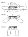
- the gripping mechanism includes two worm wheels 7 and 8.
- the worm wheels 7 and 8 are mounted on the pivot pins 5 and 6, respectively.
- the worm wheel 7 is pivotally movable about the pivot pin 5, and the worm wheel 8 is pivotally movable about the pivot pin 6.
- the worm wheel 7 is fixed to one end of the first link 1, and the worm wheel 8 is fixed to one end of the third link 3.
- the first link 1 is integrally rotatable with the worm wheel 7, and the third link 3 is integrally rotatable with the worm wheel 8.
- the worm wheel 7 may be integrally formed with the first link 1, and the worm wheel 8 may be integrally formed with the third link 3.
- a spring 16 is mounted between the support wall 18 and the flange 11 a, and a spring 17 is mounted between the support wall 19 and the flange 11 a, with residual compressive restoring forces of the springs 16 and 17 being retained, respectively.
- the flange 11a, the springs 16 and 17, and the support walls 18 and 19 constitute centering means 20 for the worms 9 and 10.
- the worm wheel 7 starts rotating in V direction in FIG. 1B by rotation of the worm 9, thereby rotating the first link 1 connected to the worm wheel 7 in V direction.
- the third link 3 is rotated in W direction in FIG. 1B by rotation of the worm 10.
- FIGS. 4A through 4C show examples, in the case where smaller-sized articles 83 and 84 are gripped. Similarly to the above case, positional displacement of the article 83, 84 can be eliminated by moving the first link 1 and the third link 3 in association with translational movement of the shaft 11, whereby the gripping mechanism is allowed to perform a gripping operation.
- the worms 9 and 10 have helical grooves in opposite directions to each other, an arrangement of pivotally moving the first link 1 and the third link 3 in opposite directions to each other by rotating the shaft. 11 can be realized with a simplified arrangement.
- a torque between a first link 1 and a second link 2 by rotation of a shaft 11 is twice of a torque between the second link 2 and a third link 3.
- This arrangement corresponds to a general phenomenon that a moment of force at a base end of a structural member is larger than a moment of force at a distal end thereof, in the case where a load is applied to the structural member.
- the reduction ratio of the worm gear at the base end of the joint mechanism is twice of the reduction ratio of the worm gear at the distal end thereof with respect to rotation of the shaft 11, a portion of the link, close to a palm member 4, is capable of receiving a larger moment of force. Accordingly, a load performance of the joint mechanism in performing a gripping operation is increased.
- the angle "A" by rotation of the shaft 11 becomes smaller than the angle "B, and unbalance may occur between the first link 1 and the third link 3.
- the unbalance can be eliminated by translational movement of the shaft 11.
- the second embodiment is advantageous in easily eliminating a difference in generated torque, and easily realizing a joint mechanism capable of receiving a proper moment of force suitable for the structure of the joint mechanism.
- the resisting means includes a sleeve 32 fixed to a second link 2, and a viscous member 33.
- the shaft 31 extends through the sleeve 32.
- the viscous member 33 is filled in a space between the sleeve 32 and the shaft 31.
- a desirable viscosity of the viscous member 33 is a viscosity capable of moving the shaft 31 at a speed equal to or smaller than about 10 mm/sec by the weight of the shaft 31.
- the material for the viscous member 33 is preferably a gel material or an oil material having a large viscosity.
- FIGS. 7A through 7C are diagrams showing a construction of a joint mechanism in accordance with the fourth embodiment of the invention.
- resisting means is provided, in place of the centering means in the first embodiment.
- the resisting means in the fourth embodiment is different from the resisting means in the third embodiment.
- a flangless shaft 41 is used in the fourth embodiment.
- the other arrangement in the fourth embodiment is substantially the same as the corresponding arrangement in the first embodiment.
- the viscous member 42 is operable to generate a resistance force depending on a relative speed between the pivot pin 5 and the worm wheel 47, and a resistance force depending on a relative speed between the pivot pin 6 and the worm wheel 48. This arrangement enables to prevent a first link 1 and a third link 3 from abruptly and pivotally moving.
- the operation of the fourth embodiment is substantially the same as the operation of the third embodiment, as shown in FIGS. 7B and 7C , and the effect of the fourth embodiment is substantially the same as the effect of the third embodiment.
- FIGS. 8A and 8B , and FIGS. 9A through 9C are diagrams showing a construction of a joint mechanism in accordance with the fifth embodiment of the invention.
- FIG. 8A shows a brake mechanism 50 as a braking mechanism.
- the brake mechanism 50 has a solenoid.
- the brake mechanism 50 includes a magnet 52 made of a magnetic material, a pad 51 constituted of an elastic member such as a rubber, and attached to a distal end of the magnet 52, a bottomed cylindrical yoke 54 made of a magnetic material, a ring-like coil 53 provided in the yoke 54, and a spring 55 wound at the other end of the magnet 52 at a position opposite to the pad 51 and inside the yoke 54.
- FIG. 8A shows a de-energized state, wherein the spring 55 has a free length.
- FIG. 8B shows an energized state, wherein a magnetic flux generated around the coil 53 is guided along the yoke 54, and the magnet 52 is attracted inwardly against a resilient force of the spring 55 by a magnetic force.
- FIG. 9A shows the entirety of the joint mechanism provided with the brake mechanism 50.
- the arrangement of the fifth embodiment is substantially the same as the arrangement of the first embodiment except for the brake mechanism 50.
- the brake mechanism 50 is loaded on a third link 3, and is normally set in an energized state.
- the reference numerals 58 and 59 in FIG. 9A each indicates a pivot pin.
- a frictional plate 57 is rigidly fixed to the pivot pin 59 on the third link 3. In other words, the frictional plate 57 is fixed to a second link 2.
- Angle sensors 71 and 72 are mounted on the second link 2.
- the angle sensor 71 is operable to measure the angle "A" of a first link 1 with respect to the second link 2.
- the angle sensor 72 is operable to measure the angle "B" of the third link 3 with respect to the second link 2.
- the angle sensors 71 and 72 are connected to an external controller (not shown) for communication of a signal.
- the controller is operable to control the brake mechanism 50 and a motor 13, based on a signal outputted from the angle sensors 71 and 72.
- the other arrangement of the fifth embodiment is substantially the same as the corresponding arrangement of the first embodiment.
- the fifth embodiment is advantageous in obtaining an intended stationary state of a joint mechanism by providing the brake mechanism 50, and fixing the third link 3 with respect to the second link 2 so that the third link 3 is not pivotally rotated relative to the second link 2.
- the fifth embodiment is advantageous in gripping various kinds of articles after the joint mechanism is adjusted to an intended stationary state suitable for gripping the articles.
- substantially two degrees of freedom are obtained by using a single motor.
- the angle sensors 71 and 72 are provided as means for detecting the angles "A” and "B".
- the angles "A” and “B” may be detected by image measurement using e.g. an external camera.
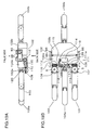
- FIGS. 10A and 10B , and FIGS. 11A through 11C are diagrams showing a construction of a joint mechanism in accordance with the sixth embodiment of the invention. Parts with the same reference numerals as in the first embodiment indicate the same parts as in the first embodiment.
- FIGS. 10A and 10B show a third link 3 and parts to be loaded on the third link 3 in the sixth embodiment, wherein FIG. 10B is a side view, and FIG. 10A is a plan view.
- the reference numeral 61 indicates a clutch mechanism as a clutching mechanism constituted of an electromagnet.
- the clutch mechanism 61 is fixed to the third link 3, and a pivot pin 6 is mountable in the clutch mechanism 61.
- Worm wheels 67 and 68 are identical in shape to the worm wheels 7 and 8 in the first embodiment, but are different from the worm wheels 7 and 8 in that the worm wheels 67 and 68 are made of a magnetic material.
- the worm wheel 68 is different from the worm wheel 8 in the first embodiment in that the worm wheel 68 is not fixed to the third link 3.
- Angle sensors 71 and 72 are the same as the angle sensors 71 and 72 in the fifth embodiment.
- the clutch mechanism 61 is operable to selectively connect and disconnect a transmission path of a driving force from a motor 13 to the third link 3 by switching between a connected state and a disconnected state of the worm wheel 68 with respect to the third link 3.
- the clutch mechanism 61 is operable to connect a transmission path of a driving force by a frictional force resulting from a magnetic attraction force.
- FIG. 10A when the clutch mechanism 61 is de-energized, the worm wheel 68 is disengaged from the third link 3, and accordingly, the driving force of the motor 13 is not transmitted to the third link 3. In other words, the worm wheel 68 is freely rotatable with respect to the third link 3.
- the clutch mechanism 61 when the clutch mechanism 61 is energized, the worm wheel 68 is magnetically attracted to the clutch mechanism 61, whereby the worm wheel 68 is integrally rotatable with the third link 3.
- distributing a driving force from a limited number of motors to plural joints, providing a clutch mechanism suitable for the joints, and fixing the joints at an intended position enables to provide substantially a change in degree of freedom by using the limited number of motors.
- the joint mechanisms have been described as examples of a gripping mechanism.
- the invention is not limited to the above.
- the invention may be applicable to a joint mechanism having a purpose of use other than the above, in place of a link mechanism for gripping an article.
- the first link 1 and a third link 3 are allowed to grip the article 85 along the shape of the article 85 by rotations and axial movements of a shaft 11 in the joint mechanism 102 and a shaft 11 in the joint mechanism 103.
- a gripping operation is performed.
- first link 1 of the joint mechanism 102 and the palm member 75 may be integrally constructed.
- the integrally constructed and bent-shaped unit serves as a first link
- the first link is supported on the wrist member 76 serving as a supporter
- the first link 1 of the joint mechanism 103 is linked to the first link.
- the first link 1 of the joint mechanism 103 and the palm member 75 may be integrally constructed.
- a gear 212 mounted on a shaft 11 is arranged on the outside of a worm 9.
- the gear 12 is mounted between the paired worms 9 and 10 mounted at both ends of the shaft 11
- the worm 9 is disposed at an intermediate portion of the shaft 11
- the gear 212 is disposed on the outside of the worm 9.
- a worm wheel 7 on a first link 1 is disposed at a position slightly closer to a middle portion of a second link 2, in place of being disposed at one end of the second link 2.
- the distance between the worm wheels 7 and 8 can be reduced, and the distance between the first link 1 and a third link 3 can be reduced.
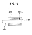
- the fixing means is not limited to the arrangement constituted of a key and a key groove.
- a worm may be rotatably mounted on a shaft, and the worm may be fixed to the shaft by an adhesive agent.
- the worm 309 may be fixed to the shaft 311 by radially forming a threaded hole 309c through the worm 309, and fastening a screw 321 as a fixing member in the threaded hole 309c.
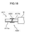
- a torque limiter 420 for protecting a gear and the like against a rotating torque.
- the torque limiter 420 is provided in a driving force transmitting system between a motor 13 and a shaft 11.
- the torque limiter 420 includes a first gear 415a, a second gear 415b, a spring 431 for urging the first gear 415a and the second gear 415b in directions toward each other, and flanges 430a and 430b for absorbing a reaction force of the spring 431.
- the flanges 430a and 430b are mounted on a shaft 430 extending through the first gear 415a and the second gear 415b.
- the first gear 415a and the second gear 415b are mounted between the paired flanges 430a and 430b along with the spring 431 in a compressed state, and are urged toward each other by a resilient force of the spring 431.
- a friction is caused between the first gear 415a and the second gear 415b, and a torque to be transmitted by the stationary frictional force is set to such an amount that does not damage a gear or a like element. If a torque larger than a maximum stationary frictional force is generated, a slip is caused between the first gear 415a and the second gear 415b, and the first gear 415a and the second gear 415b are rotated relative to each other.
- a gear 112 is mounted on the shaft 111.
- the gear 112 is connected to a gear 114 connected to the motor 113 via a gear 115 so that a driving force of the motor 113 is transmittable to the shaft 111.
- the finger mechanism 101 is integrally and pivotally movable with a worm gear 107
- the finger mechanism 103 is integrally and pivotally movable with a worm gear 108.
- the finger mechanism 101 and the finger mechanism 103 are each operable to change the open angle thereof by driving the motor 113.
- the open angles of the finger mechanism 101 and the finger mechanism 103 are respectively changeable depending on the shape or the like of an article to be gripped.
- a pin support portion 102c for supporting a pivot pin 6 is formed on the first palm portion 102a.
- a pivot pin 120 for pivotally supporting the finger mechanism 101 in a gripping direction is mounted on the pin support portion 102c.
- the finger mechanisms 103, 104a, and 104b are each pivotally movable in the gripping direction.
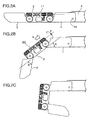
- FIGS. 20A through 20C are diagrams showing a construction of a joint mechanism in accordance with the twelfth embodiment of the invention. Parts with the same reference numerals as in the first embodiment indicate the same parts as in the first embodiment.
- the joint mechanism is operable to change the angle of the first link 1 and the angle of the third link 3 with respect to the second link 2 relative to each other by driving a motor 13.
- the second link 2 is pivotally moved about an axis of a pivot pin 6, with the third link 3 being kept unmoved.
- the pivot angle of the first link 1 with respect to the second link 2 is determined by a force to be applied from the upper body member 4.
- FIG. 20C shows an example, wherein the force to be applied to the third link 3 is larger than the force to be applied to the first link 1.
- the relation between the pivot angles of the first link 1 and the third link 3 is determined depending on the magnitudes of forces to be applied to the first link 1 and the third link 3. Accordingly, providing the braking mechanism described in the fifth embodiment, or the clutch mechanism described in the sixth embodiment in the joint mechanism of the twelfth embodiment enables to positively control the pivot angles of the first link 1 and the third link 3. Thereby, the pivot angles of the first link 1 and the third link 3 can be adjusted to an intended angle, and the joint mechanism is easily set in any posture.
- the connecting member may be constituted of an integrally formed shaft.
- the first worm and the second worm may have helical grooves in opposite directions to each other.
- an arrangement of pivotally moving the first link and the third link in opposite directions to each other by rotating the connecting member can be realized with a simplified arrangement.
- the joint mechanism may further include a motor, fixed to the second link, for rotating the connecting member.
- the joint mechanism may further include centering means for restoring the connecting member to a predetermined position in an axis direction.
- centering means for restoring the connecting member to a predetermined position in an axis direction.
- the centering means may include a resilient member, and the resilient member may be operable to restore the connecting member to the predetermined position by a resilient force of the resilient member.
- the connecting member can be restored to the predetermined position with a simplified arrangement.
- a reduction ratio between the first worm and the first worm wheel may be set larger than a reduction ratio between the second worm and the second worm wheel.
- the first link serving as a base link to be connected to the supporter receives a larger torque from the worm and the worm wheel.
- the joint mechanism may further include resisting means for generating a resistance force depending on a relative moving speed of the connecting member with respect to the second link in the axis direction.
- resisting means for generating a resistance force depending on a relative moving speed of the connecting member with respect to the second link in the axis direction.
- This arrangement is advantageous in suppressing the connecting member from abruptly moving in the axis direction resulting from a change in gravitational force, the weight of the connecting member, or the like, depending on the direction of the second link.
- the arrangement is advantageous in obtaining a stable operation of the joint mechanism when the joint mechanism approaches an article for gripping the article.
- the joint mechanism may further include resisting means for generating a resistance force depending on relative rotational speeds of the first worm wheel and the second worm wheel with respect to the second link. This arrangement enables to suppress the first link and the third link from pivotally and abruptly moving.
- the resisting means may include a viscous member to be provided in a space between the two members subjected to the relative movement.
- the joint mechanism may further include at least one of a braking mechanism for preventing a change in angle of the first link with respect to the second link, and a braking mechanism for preventing a change in angle of the third link with respect to the second link.
- the positions of the first link, the second link, and the third link can be stabilized without a change in angle between the second link, and the first link or the third link.
- the direction of at least one of the first link and the third link can be defined in advance before the joint mechanism performs a predetermined operation such as an operation of gripping an article.
- the arrangement is advantageous in optimally adjusting the posture of the joint mechanism immediately before the joint mechanism performs a predetermined operation.
- the joint mechanism may further include a clutching mechanism for selectively transmitting a driving force on at least one of a driving force transmission path from the motor to the first link, and a driving force transmission path from the motor to the third link.
- the joint mechanism may further include an angle sensor for detecting a relative angle between the first link or the third link having the clutching mechanism, and the second link, wherein the clutching mechanism is operated based on an output of the angle sensor.
- the joint mechanism may further include: multiple gears, between the motor and the connecting member, for transmitting a torque of the motor; and a torque limiter for cutting off transmission of an exceedingly large torque.
- This arrangement enables to prevent damage of a gear for transmitting a driving force from the motor to the connecting member.
- the article can be securely gripped in the adjusted state.
- torques to be applied to the worms via the worm wheels may be unbalanced to each other.
- the worms may be displaced in the axis direction thereof by a distance corresponding to a torque difference between the worm wheels.
- the worms are integrally displaced in the axis direction so that the torques to be applied from the article to the first link and the third link are balanced.
- the worm wheels are rotated in identical directions to each other; or one of the worm wheels whose applied torque is larger is kept unrotated, and the other of the worm wheels is rotated.
- a relation: dA ⁇ dB ⁇ 0 is established when the worms are moved in the axis direction.
- rotating the connecting member depending on the size of an article to be gripped enables to grip various kinds of articles different in size, and eliminate unbalance between the torques to be applied to the first link and the third link resulting from axial movement of the connecting member, depending on the shape of the article or positional relation of the article with respect to the first link and the third link. Accordingly, this arrangement enables to realize a gripping mechanism having degrees of freedom necessary for a gripping operation, with a simplified construction, and capable of gripping an article depending on the shape of the article, without using multiple motors.
- the joint mechanism may further include an angle sensor for detecting a relative angle between the parts, wherein the braking mechanism is operated, using a signal based on an output of the angle sensor.
- Still another aspect of the invention is directed to a joint device including: the aforementioned joint mechanism; and a supporter for supporting the joint mechanism.
- the joint mechanism according to the invention can be utilized as a gripping mechanism corresponding to a hand finger to be used in a robotic manipulator, and a joint mechanism for a robot.
Landscapes
- Engineering & Computer Science (AREA)
- Robotics (AREA)
- Mechanical Engineering (AREA)
- Manipulator (AREA)
- Seal Device For Vehicle (AREA)
- Steering Control In Accordance With Driving Conditions (AREA)
- Chair Legs, Seat Parts, And Backrests (AREA)
- Transmission Devices (AREA)
- Spinning Or Twisting Of Yarns (AREA)
Applications Claiming Priority (2)
| Application Number | Priority Date | Filing Date | Title |
|---|---|---|---|
| JP2006330629 | 2006-12-07 | ||
| PCT/JP2007/073671 WO2008069306A1 (ja) | 2006-12-07 | 2007-12-07 | 関節機構及び関節装置 |
Publications (3)
| Publication Number | Publication Date |
|---|---|
| EP2093027A1 true EP2093027A1 (de) | 2009-08-26 |
| EP2093027A4 EP2093027A4 (de) | 2010-03-03 |
| EP2093027B1 EP2093027B1 (de) | 2011-02-09 |
Family
ID=39492181
Family Applications (1)
| Application Number | Title | Priority Date | Filing Date |
|---|---|---|---|
| EP07859749A Not-in-force EP2093027B1 (de) | 2006-12-07 | 2007-12-07 | Gelenkmechanismus |
Country Status (7)
| Country | Link |
|---|---|
| US (2) | US8141925B2 (de) |
| EP (1) | EP2093027B1 (de) |
| JP (1) | JP4783434B2 (de) |
| CN (1) | CN101547773B (de) |
| AT (1) | ATE497866T1 (de) |
| DE (1) | DE602007012468D1 (de) |
| WO (1) | WO2008069306A1 (de) |
Cited By (1)
| Publication number | Priority date | Publication date | Assignee | Title |
|---|---|---|---|---|
| EP3955420A1 (de) * | 2020-08-14 | 2022-02-16 | Siemens Aktiengesellschaft | Antrieb für eine roboterachse |
Families Citing this family (68)
| Publication number | Priority date | Publication date | Assignee | Title |
|---|---|---|---|---|
| JP2008178939A (ja) * | 2007-01-24 | 2008-08-07 | Toyota Motor Corp | ロボットハンド |
| US9748824B2 (en) | 2012-06-25 | 2017-08-29 | Systems Machine Automation Components Corporation | Linear actuator with moving central coil and permanent side magnets |
| US9731418B2 (en) | 2008-01-25 | 2017-08-15 | Systems Machine Automation Components Corporation | Methods and apparatus for closed loop force control in a linear actuator |
| US9375848B2 (en) * | 2012-06-25 | 2016-06-28 | Systems Machine Automation Components Corporation | Robotic finger |
| US7752765B2 (en) * | 2008-03-19 | 2010-07-13 | Marc Lev Shapiro | Gear actuated angle measurement tool |
| JP4581117B1 (ja) * | 2010-05-24 | 2010-11-17 | 国立大学法人東京工業大学 | 開閉両方向に力を出せる把持装置 |
| JP5963755B2 (ja) | 2010-09-23 | 2016-08-03 | システムズ マシーンズ オートメーション コンポーネンツ コーポレイション | 低コストのマルチコイルリニアアクチュエータ |
| JP2012066351A (ja) * | 2010-09-24 | 2012-04-05 | Yaskawa Electric Corp | ロボット用ハンドユニットおよびロボット |
| CN101966533B (zh) * | 2010-09-26 | 2012-07-04 | 中国兵器工业第五九研究所 | 滚轧机床主轴圆周相位变差调整机构 |
| US8833826B2 (en) | 2011-03-21 | 2014-09-16 | Sri International | Mobile robotic manipulator system |
| US8967010B2 (en) * | 2011-03-31 | 2015-03-03 | Covidien Lp | System and method for providing a selectable multiple output motor |
| US9267585B2 (en) | 2011-06-02 | 2016-02-23 | Empire Technology Development Llc | Actuator with joints |
| GB201200167D0 (en) * | 2012-01-05 | 2012-02-15 | Rsl Steeper Group Ltd | An artificial hand component |
| US9099148B2 (en) * | 2012-03-30 | 2015-08-04 | Oracle International Corporation | Magnetic Z-directional clutch |
| KR101340294B1 (ko) | 2012-07-04 | 2013-12-11 | 한국과학기술원 | 관절 잠금 장치를 구비하는 불충분 구동 로봇 핑거 |
| JP6014272B2 (ja) * | 2012-11-30 | 2016-10-25 | コングスベルグ オートモーティヴ アクチボラゲット | シフトバイワイヤ型トランスミッション用の回転シフトアクチュエータ |
| JP5655877B2 (ja) * | 2013-02-12 | 2015-01-21 | 株式会社安川電機 | 関節機構およびロボット |
| US9138897B1 (en) * | 2013-04-30 | 2015-09-22 | Sandia Corporation | Mechanisms for employment with robotic extensions |
| US20150151433A1 (en) * | 2013-12-02 | 2015-06-04 | Harris Corporation | Compact robotic gripper |
| US9871435B2 (en) | 2014-01-31 | 2018-01-16 | Systems, Machines, Automation Components Corporation | Direct drive motor for robotic finger |
| US10807248B2 (en) | 2014-01-31 | 2020-10-20 | Systems, Machines, Automation Components Corporation | Direct drive brushless motor for robotic finger |
| ES2857728T3 (es) | 2014-09-17 | 2021-09-29 | Soft Robotics Inc | Cubo de fijación de actuadores robóticos blandos y conjunto de agarre y actuadores electroadhesivos |
| US9492928B2 (en) * | 2014-11-05 | 2016-11-15 | Toyota Motor Engineering & Manufacturing North America, Inc. | Interconnected phalanges for robotic gripping |
| US10189168B2 (en) * | 2014-11-18 | 2019-01-29 | Soft Robotics, Inc. | Soft robotic actuator enhancements |
| JP6257543B2 (ja) * | 2015-02-23 | 2018-01-10 | マブチモーター株式会社 | 逆転防止機構および減速機付モータ |
| CN104742110A (zh) * | 2015-03-27 | 2015-07-01 | 上海交通大学 | 一种电力线巡检机器人的末端执行机构及其线上锁紧方法 |
| US9976646B2 (en) * | 2015-05-28 | 2018-05-22 | Automotive Research & Testing Center | Angle regulation device |
| US10429211B2 (en) | 2015-07-10 | 2019-10-01 | Systems, Machines, Automation Components Corporation | Apparatus and methods for linear actuator with piston assembly having an integrated controller and encoder |
| US10215802B2 (en) | 2015-09-24 | 2019-02-26 | Systems, Machines, Automation Components Corporation | Magnetically-latched actuator |
| US10486645B2 (en) * | 2015-11-20 | 2019-11-26 | Ford Global Technologies, Llc | Lock for vehicle active front steering system |
| US10675723B1 (en) | 2016-04-08 | 2020-06-09 | Systems, Machines, Automation Components Corporation | Methods and apparatus for inserting a threaded fastener using a linear rotary actuator |
| US10865085B1 (en) | 2016-04-08 | 2020-12-15 | Systems, Machines, Automation Components Corporation | Methods and apparatus for applying a threaded cap using a linear rotary actuator |
| US10016901B2 (en) * | 2016-05-04 | 2018-07-10 | X Development Llc | Sprung worm gripper for a robotic device |
| US10011019B1 (en) * | 2016-05-04 | 2018-07-03 | X Development Llc | Wind-up gripper for a robotic device |
| US9718195B1 (en) | 2016-06-09 | 2017-08-01 | X Development Llc | Cylindrical worm drive robotic gripper |
| US10281037B2 (en) | 2016-08-09 | 2019-05-07 | Nidec Motors & Actuators (Germany) Gmbh | Device and a method for distributing torque in a worm gear assembly |
| CN106395401A (zh) * | 2016-08-31 | 2017-02-15 | 广西联壮科技股份有限公司 | 工作宽度可调型抓边码垛装置 |
| US10205355B2 (en) | 2017-01-03 | 2019-02-12 | Systems, Machines, Automation Components Corporation | High-torque, low-current brushless motor |
| USD846615S1 (en) * | 2017-07-18 | 2019-04-23 | Mitsubishi Electric Corporation | Manipulator for robot |
| JP1605294S (de) * | 2017-07-18 | 2019-11-25 | ||
| USD847243S1 (en) * | 2017-07-18 | 2019-04-30 | Mitsubishi Electric Corporation | Manipulator for robot |
| JP1605292S (de) * | 2017-07-18 | 2019-11-25 | ||
| JP1605291S (de) * | 2017-07-18 | 2019-11-25 | ||
| USD852859S1 (en) | 2017-07-18 | 2019-07-02 | Mitsubishi Electric Corporation | Manipulator for robot |
| JP1613980S (de) * | 2018-03-29 | 2020-03-09 | ||
| JP1613032S (de) * | 2018-03-29 | 2020-03-02 | ||
| US11523839B2 (en) * | 2018-04-03 | 2022-12-13 | Intuitive Surgical Operations, Inc. | Systems and methods for grasp adjustment based on grasp properties |
| CN108583721A (zh) * | 2018-07-13 | 2018-09-28 | 长沙紫宸科技开发有限公司 | 一种便装式仿生腿 |
| CN108583725A (zh) * | 2018-07-13 | 2018-09-28 | 长沙紫宸科技开发有限公司 | 一种便装式可自锁带自主分布动力的仿生机械腿 |
| CN109732638B (zh) * | 2018-12-06 | 2020-08-18 | 山东省科学院自动化研究所 | 一种平移回转型夹持手爪及其工作方法、机器人系统 |
| KR102182377B1 (ko) * | 2019-03-04 | 2020-11-24 | 한국기계연구원 | 사물 형상 적응형 파지 모듈 |
| CN109916466B (zh) * | 2019-03-05 | 2020-08-04 | 广州能源检测研究院 | 一种检定或校准被检流量计安装对中装置 |
| CN110002219A (zh) * | 2019-04-23 | 2019-07-12 | 林友钢 | 一种双头蜗杆自锁抱持机构及其实现方法 |
| US11738893B2 (en) | 2019-04-30 | 2023-08-29 | Soft Robotics, Inc. | Picking, placing, and scanning bagged clothing and other articles |
| US11273978B2 (en) | 2019-05-03 | 2022-03-15 | Oshkosh Corporation | Refuse vehicle with electric lift |
| US11434681B2 (en) | 2019-05-03 | 2022-09-06 | Oshkosh Corporation | Electric tailgate for electric refuse vehicle |
| US11447334B2 (en) | 2019-05-03 | 2022-09-20 | Oshkosh Corporation | Electric grasping apparatus for refuse vehicle |
| US11505404B2 (en) | 2019-05-03 | 2022-11-22 | Oshkosh Corporation | Electric side loader arms for electric refuse vehicle |
| US11254500B2 (en) | 2019-05-03 | 2022-02-22 | Oshkosh Corporation | Refuse vehicle with electric reach apparatus |
| RU2727893C1 (ru) * | 2019-05-13 | 2020-07-24 | Общество с ограниченной ответственностью "МОТОРИКА" | Палец протеза со спироидным редуктором и модульная конструкция протеза верхней конечности |
| US11931270B2 (en) | 2019-11-15 | 2024-03-19 | Touch Bionics Limited | Prosthetic digit actuator |
| US20230033693A1 (en) * | 2020-01-23 | 2023-02-02 | UNIVERSITé LAVAL | Mechanical finger for gripper |
| US12017346B2 (en) * | 2021-03-24 | 2024-06-25 | City University Of Hong Kong | Articulated actuated finger with self-locking joints |
| JP7653868B2 (ja) * | 2021-08-31 | 2025-03-31 | 株式会社日立製作所 | ロボットハンドおよびロボットシステム |
| KR102715271B1 (ko) * | 2022-01-10 | 2024-10-11 | 만드로 주식회사 | 의수용 손가락 내장형 모터 및 감속기 구조 |
| US20240374402A1 (en) * | 2022-01-10 | 2024-11-14 | Mand.Ro Co., Ltd. | Structure of motor and reducer built into prosthetic finger |
| JP2023163876A (ja) * | 2022-04-28 | 2023-11-10 | 株式会社デンソー | ロボットハンド |
| CN115194798B (zh) * | 2022-07-12 | 2024-11-12 | 深圳金博仕机器人有限公司 | 一种具有弹性结构的机械手指 |
Family Cites Families (18)
| Publication number | Priority date | Publication date | Assignee | Title |
|---|---|---|---|---|
| JPS5662785A (en) * | 1979-10-25 | 1981-05-28 | Kogyo Gijutsuin | Griper |
| US4547121A (en) * | 1983-09-30 | 1985-10-15 | The United States Of America As Represented By The Administrator Of The National Aeronautics And Space Administration | Self-locking telescoping manipulator arm |
| DE3434009A1 (de) * | 1984-09-15 | 1986-03-27 | Index-Werke Kg Hahn & Tessky, 7300 Esslingen | Werkstueck-handhabungsgeraet |
| JP2697828B2 (ja) | 1987-08-28 | 1998-01-14 | 株式会社日立製作所 | 車輌用自動変速装置 |
| JPH0158851U (de) * | 1987-10-08 | 1989-04-13 | ||
| JPH01140984A (ja) | 1987-11-24 | 1989-06-02 | Daikin Ind Ltd | 多関節ロボットのアーム構造 |
| US4957320A (en) * | 1988-08-31 | 1990-09-18 | Trustees Of The University Of Pennsylvania | Methods and apparatus for mechanically intelligent grasping |
| US5501498A (en) * | 1988-08-31 | 1996-03-26 | The Trustees Of The University Of Pennsylvania | Methods and apparatus for mechanically intelligent grasping |
| JPH0311535A (ja) | 1989-06-08 | 1991-01-18 | Nec Kagoshima Ltd | 蛍光表示管 |
| JPH0311535U (de) * | 1989-06-19 | 1991-02-05 | ||
| CN1052445A (zh) * | 1989-12-12 | 1991-06-26 | 杭州电子工业学院 | 三感觉机械手 |
| JPH05185385A (ja) | 1992-01-10 | 1993-07-27 | Mitsubishi Heavy Ind Ltd | 多関節形マニピュレータアーム |
| JPH06305455A (ja) | 1993-04-22 | 1994-11-01 | Osaka Gas Co Ltd | クローラ式走行装置 |
| GB9404830D0 (en) * | 1994-03-12 | 1994-04-27 | Lothian Health Board | Hand prosthesis |
| JP3245095B2 (ja) | 1997-08-07 | 2002-01-07 | 川▲崎▼ 晴久 | ロボットハンド |
| JP2001038669A (ja) | 1999-07-30 | 2001-02-13 | Masanobu Yatsugi | 駆動力伝達機構 |
| CA2500005C (en) * | 2002-09-26 | 2011-12-06 | Barrett Technology, Inc. | Intelligent, self-contained robotic hand |
| CN1785609A (zh) * | 2005-12-22 | 2006-06-14 | 复旦大学 | 新型联动机械手结构设计 |
-
2007
- 2007-12-07 AT AT07859749T patent/ATE497866T1/de not_active IP Right Cessation
- 2007-12-07 US US12/517,710 patent/US8141925B2/en active Active
- 2007-12-07 WO PCT/JP2007/073671 patent/WO2008069306A1/ja not_active Ceased
- 2007-12-07 CN CN200780044826.6A patent/CN101547773B/zh not_active Expired - Fee Related
- 2007-12-07 DE DE602007012468T patent/DE602007012468D1/de active Active
- 2007-12-07 EP EP07859749A patent/EP2093027B1/de not_active Not-in-force
- 2007-12-07 JP JP2008548348A patent/JP4783434B2/ja active Active
-
2012
- 2012-02-15 US US13/397,212 patent/US8251420B2/en not_active Expired - Fee Related
Cited By (1)
| Publication number | Priority date | Publication date | Assignee | Title |
|---|---|---|---|---|
| EP3955420A1 (de) * | 2020-08-14 | 2022-02-16 | Siemens Aktiengesellschaft | Antrieb für eine roboterachse |
Also Published As
| Publication number | Publication date |
|---|---|
| EP2093027A4 (de) | 2010-03-03 |
| JP4783434B2 (ja) | 2011-09-28 |
| CN101547773B (zh) | 2011-04-13 |
| US20120137807A1 (en) | 2012-06-07 |
| DE602007012468D1 (de) | 2011-03-24 |
| US8141925B2 (en) | 2012-03-27 |
| EP2093027B1 (de) | 2011-02-09 |
| US8251420B2 (en) | 2012-08-28 |
| WO2008069306A1 (ja) | 2008-06-12 |
| CN101547773A (zh) | 2009-09-30 |
| JPWO2008069306A1 (ja) | 2010-03-25 |
| US20100005918A1 (en) | 2010-01-14 |
| ATE497866T1 (de) | 2011-02-15 |
Similar Documents
| Publication | Publication Date | Title |
|---|---|---|
| EP2093027B1 (de) | Gelenkmechanismus | |
| JP7288926B2 (ja) | 脚付きロボット用のねじアクチュエータ | |
| US11465277B2 (en) | Cable-driven system with magnetorheological fluid clutch apparatuses | |
| CN108698223B (zh) | 机器人关节和具有至少一个这种机器人关节的机器人 | |
| Schiele et al. | Bowden cable actuator for force-feedback exoskeletons | |
| EP4171898B1 (de) | Manipulatormodul | |
| US20190160658A1 (en) | Joint unit, joint system, robot for manipulation and/or transportation, robotic exoskeleton system and method for manipulation and/or transportation | |
| EP2732937A1 (de) | Roboterhand und roboter | |
| CN212218476U (zh) | 扭矩可控的旋转驱动器及机器人系统 | |
| CN115349062B (zh) | 使用磁流变流体离合器装置的低阻抗致动设备 | |
| EP4316749B1 (de) | Robotergreifer | |
| EP3616855B1 (de) | Aktuatoranordnung und verfahren zur drehbetätigung um eine schwenkachse sowie verwendung der aktuatoranordnung | |
| CN110842968A (zh) | 一种采用绞盘和腱传动的拮抗式驱动装置 | |
| US20150080908A1 (en) | Energy balance mechanism for flexure joint | |
| Letier et al. | Bowden cable actuator for torque-feedback in haptic applications | |
| Schmitz et al. | A Concept for a robot arm with adjustable series clutch actuators and passive gravity compensation for enhanced safety | |
| JP2023044961A (ja) | 振動抑制装置 | |
| JP2001121460A (ja) | ロボット用パラレルリンク機構 | |
| US20090107281A1 (en) | Spring-based vectoring system for robotic aplications | |
| Kajikawa et al. | A new VSJ mechanism for multi-directional passivity and quick response | |
| CN113664818A (zh) | 关节储能可调装置及机器人 |
Legal Events
| Date | Code | Title | Description |
|---|---|---|---|
| PUAI | Public reference made under article 153(3) epc to a published international application that has entered the european phase |
Free format text: ORIGINAL CODE: 0009012 |
|
| 17P | Request for examination filed |
Effective date: 20090610 |
|
| AK | Designated contracting states |
Kind code of ref document: A1 Designated state(s): AT BE BG CH CY CZ DE DK EE ES FI FR GB GR HU IE IS IT LI LT LU LV MC MT NL PL PT RO SE SI SK TR |
|
| RIN1 | Information on inventor provided before grant (corrected) |
Inventor name: MIZUNO, OSAMU Inventor name: OKUDA, AKINOBU Inventor name: NAKAMURA, TOHRU |
|
| A4 | Supplementary search report drawn up and despatched |
Effective date: 20100128 |
|
| DAX | Request for extension of the european patent (deleted) | ||
| GRAP | Despatch of communication of intention to grant a patent |
Free format text: ORIGINAL CODE: EPIDOSNIGR1 |
|
| RTI1 | Title (correction) |
Free format text: JOINT MECHANISM |
|
| GRAS | Grant fee paid |
Free format text: ORIGINAL CODE: EPIDOSNIGR3 |
|
| GRAA | (expected) grant |
Free format text: ORIGINAL CODE: 0009210 |
|
| AK | Designated contracting states |
Kind code of ref document: B1 Designated state(s): AT BE BG CH CY CZ DE DK EE ES FI FR GB GR HU IE IS IT LI LT LU LV MC MT NL PL PT RO SE SI SK TR |
|
| REG | Reference to a national code |
Ref country code: GB Ref legal event code: FG4D |
|
| REG | Reference to a national code |
Ref country code: CH Ref legal event code: EP |
|
| REG | Reference to a national code |
Ref country code: IE Ref legal event code: FG4D |
|
| REF | Corresponds to: |
Ref document number: 602007012468 Country of ref document: DE Date of ref document: 20110324 Kind code of ref document: P |
|
| REG | Reference to a national code |
Ref country code: DE Ref legal event code: R096 Ref document number: 602007012468 Country of ref document: DE Effective date: 20110324 |
|
| REG | Reference to a national code |
Ref country code: NL Ref legal event code: VDEP Effective date: 20110209 |
|
| LTIE | Lt: invalidation of european patent or patent extension |
Effective date: 20110209 |
|
| PG25 | Lapsed in a contracting state [announced via postgrant information from national office to epo] |
Ref country code: ES Free format text: LAPSE BECAUSE OF FAILURE TO SUBMIT A TRANSLATION OF THE DESCRIPTION OR TO PAY THE FEE WITHIN THE PRESCRIBED TIME-LIMIT Effective date: 20110520 Ref country code: GR Free format text: LAPSE BECAUSE OF FAILURE TO SUBMIT A TRANSLATION OF THE DESCRIPTION OR TO PAY THE FEE WITHIN THE PRESCRIBED TIME-LIMIT Effective date: 20110510 Ref country code: PT Free format text: LAPSE BECAUSE OF FAILURE TO SUBMIT A TRANSLATION OF THE DESCRIPTION OR TO PAY THE FEE WITHIN THE PRESCRIBED TIME-LIMIT Effective date: 20110609 Ref country code: SE Free format text: LAPSE BECAUSE OF FAILURE TO SUBMIT A TRANSLATION OF THE DESCRIPTION OR TO PAY THE FEE WITHIN THE PRESCRIBED TIME-LIMIT Effective date: 20110209 Ref country code: LV Free format text: LAPSE BECAUSE OF FAILURE TO SUBMIT A TRANSLATION OF THE DESCRIPTION OR TO PAY THE FEE WITHIN THE PRESCRIBED TIME-LIMIT Effective date: 20110209 Ref country code: LT Free format text: LAPSE BECAUSE OF FAILURE TO SUBMIT A TRANSLATION OF THE DESCRIPTION OR TO PAY THE FEE WITHIN THE PRESCRIBED TIME-LIMIT Effective date: 20110209 |
|
| PG25 | Lapsed in a contracting state [announced via postgrant information from national office to epo] |
Ref country code: SI Free format text: LAPSE BECAUSE OF FAILURE TO SUBMIT A TRANSLATION OF THE DESCRIPTION OR TO PAY THE FEE WITHIN THE PRESCRIBED TIME-LIMIT Effective date: 20110209 Ref country code: FI Free format text: LAPSE BECAUSE OF FAILURE TO SUBMIT A TRANSLATION OF THE DESCRIPTION OR TO PAY THE FEE WITHIN THE PRESCRIBED TIME-LIMIT Effective date: 20110209 Ref country code: BE Free format text: LAPSE BECAUSE OF FAILURE TO SUBMIT A TRANSLATION OF THE DESCRIPTION OR TO PAY THE FEE WITHIN THE PRESCRIBED TIME-LIMIT Effective date: 20110209 Ref country code: NL Free format text: LAPSE BECAUSE OF FAILURE TO SUBMIT A TRANSLATION OF THE DESCRIPTION OR TO PAY THE FEE WITHIN THE PRESCRIBED TIME-LIMIT Effective date: 20110209 Ref country code: CY Free format text: LAPSE BECAUSE OF FAILURE TO SUBMIT A TRANSLATION OF THE DESCRIPTION OR TO PAY THE FEE WITHIN THE PRESCRIBED TIME-LIMIT Effective date: 20110209 Ref country code: BG Free format text: LAPSE BECAUSE OF FAILURE TO SUBMIT A TRANSLATION OF THE DESCRIPTION OR TO PAY THE FEE WITHIN THE PRESCRIBED TIME-LIMIT Effective date: 20110509 Ref country code: AT Free format text: LAPSE BECAUSE OF FAILURE TO SUBMIT A TRANSLATION OF THE DESCRIPTION OR TO PAY THE FEE WITHIN THE PRESCRIBED TIME-LIMIT Effective date: 20110209 Ref country code: PL Free format text: LAPSE BECAUSE OF FAILURE TO SUBMIT A TRANSLATION OF THE DESCRIPTION OR TO PAY THE FEE WITHIN THE PRESCRIBED TIME-LIMIT Effective date: 20110209 |
|
| PG25 | Lapsed in a contracting state [announced via postgrant information from national office to epo] |
Ref country code: DK Free format text: LAPSE BECAUSE OF FAILURE TO SUBMIT A TRANSLATION OF THE DESCRIPTION OR TO PAY THE FEE WITHIN THE PRESCRIBED TIME-LIMIT Effective date: 20110209 Ref country code: EE Free format text: LAPSE BECAUSE OF FAILURE TO SUBMIT A TRANSLATION OF THE DESCRIPTION OR TO PAY THE FEE WITHIN THE PRESCRIBED TIME-LIMIT Effective date: 20110209 |
|
| PG25 | Lapsed in a contracting state [announced via postgrant information from national office to epo] |
Ref country code: CZ Free format text: LAPSE BECAUSE OF FAILURE TO SUBMIT A TRANSLATION OF THE DESCRIPTION OR TO PAY THE FEE WITHIN THE PRESCRIBED TIME-LIMIT Effective date: 20110209 Ref country code: SK Free format text: LAPSE BECAUSE OF FAILURE TO SUBMIT A TRANSLATION OF THE DESCRIPTION OR TO PAY THE FEE WITHIN THE PRESCRIBED TIME-LIMIT Effective date: 20110209 Ref country code: RO Free format text: LAPSE BECAUSE OF FAILURE TO SUBMIT A TRANSLATION OF THE DESCRIPTION OR TO PAY THE FEE WITHIN THE PRESCRIBED TIME-LIMIT Effective date: 20110209 |
|
| PLBE | No opposition filed within time limit |
Free format text: ORIGINAL CODE: 0009261 |
|
| STAA | Information on the status of an ep patent application or granted ep patent |
Free format text: STATUS: NO OPPOSITION FILED WITHIN TIME LIMIT |
|
| 26N | No opposition filed |
Effective date: 20111110 |
|
| REG | Reference to a national code |
Ref country code: DE Ref legal event code: R097 Ref document number: 602007012468 Country of ref document: DE Effective date: 20111110 |
|
| PG25 | Lapsed in a contracting state [announced via postgrant information from national office to epo] |
Ref country code: IT Free format text: LAPSE BECAUSE OF FAILURE TO SUBMIT A TRANSLATION OF THE DESCRIPTION OR TO PAY THE FEE WITHIN THE PRESCRIBED TIME-LIMIT Effective date: 20110209 |
|
| PG25 | Lapsed in a contracting state [announced via postgrant information from national office to epo] |
Ref country code: MC Free format text: LAPSE BECAUSE OF NON-PAYMENT OF DUE FEES Effective date: 20111231 |
|
| REG | Reference to a national code |
Ref country code: CH Ref legal event code: PL |
|
| REG | Reference to a national code |
Ref country code: IE Ref legal event code: MM4A |
|
| PG25 | Lapsed in a contracting state [announced via postgrant information from national office to epo] |
Ref country code: CH Free format text: LAPSE BECAUSE OF NON-PAYMENT OF DUE FEES Effective date: 20111231 Ref country code: IE Free format text: LAPSE BECAUSE OF NON-PAYMENT OF DUE FEES Effective date: 20111207 Ref country code: LI Free format text: LAPSE BECAUSE OF NON-PAYMENT OF DUE FEES Effective date: 20111231 |
|
| PG25 | Lapsed in a contracting state [announced via postgrant information from national office to epo] |
Ref country code: MT Free format text: LAPSE BECAUSE OF FAILURE TO SUBMIT A TRANSLATION OF THE DESCRIPTION OR TO PAY THE FEE WITHIN THE PRESCRIBED TIME-LIMIT Effective date: 20110209 |
|
| PG25 | Lapsed in a contracting state [announced via postgrant information from national office to epo] |
Ref country code: LU Free format text: LAPSE BECAUSE OF NON-PAYMENT OF DUE FEES Effective date: 20111207 |
|
| PG25 | Lapsed in a contracting state [announced via postgrant information from national office to epo] |
Ref country code: IS Free format text: LAPSE BECAUSE OF FAILURE TO SUBMIT A TRANSLATION OF THE DESCRIPTION OR TO PAY THE FEE WITHIN THE PRESCRIBED TIME-LIMIT Effective date: 20110209 |
|
| PG25 | Lapsed in a contracting state [announced via postgrant information from national office to epo] |
Ref country code: TR Free format text: LAPSE BECAUSE OF FAILURE TO SUBMIT A TRANSLATION OF THE DESCRIPTION OR TO PAY THE FEE WITHIN THE PRESCRIBED TIME-LIMIT Effective date: 20110209 |
|
| PG25 | Lapsed in a contracting state [announced via postgrant information from national office to epo] |
Ref country code: HU Free format text: LAPSE BECAUSE OF FAILURE TO SUBMIT A TRANSLATION OF THE DESCRIPTION OR TO PAY THE FEE WITHIN THE PRESCRIBED TIME-LIMIT Effective date: 20110209 |
|
| PGFP | Annual fee paid to national office [announced via postgrant information from national office to epo] |
Ref country code: GB Payment date: 20131204 Year of fee payment: 7 Ref country code: DE Payment date: 20131204 Year of fee payment: 7 |
|
| PGFP | Annual fee paid to national office [announced via postgrant information from national office to epo] |
Ref country code: FR Payment date: 20131209 Year of fee payment: 7 |
|
| REG | Reference to a national code |
Ref country code: DE Ref legal event code: R119 Ref document number: 602007012468 Country of ref document: DE |
|
| GBPC | Gb: european patent ceased through non-payment of renewal fee |
Effective date: 20141207 |
|
| REG | Reference to a national code |
Ref country code: FR Ref legal event code: ST Effective date: 20150831 |
|
| PG25 | Lapsed in a contracting state [announced via postgrant information from national office to epo] |
Ref country code: DE Free format text: LAPSE BECAUSE OF NON-PAYMENT OF DUE FEES Effective date: 20150701 Ref country code: GB Free format text: LAPSE BECAUSE OF NON-PAYMENT OF DUE FEES Effective date: 20141207 |
|
| PG25 | Lapsed in a contracting state [announced via postgrant information from national office to epo] |
Ref country code: FR Free format text: LAPSE BECAUSE OF NON-PAYMENT OF DUE FEES Effective date: 20141231 |