EP2093040A1 - Procédé de fabrication d'un réservoir d'échangeur thermique et réservoir obtenu selon ledit procédé - Google Patents
Procédé de fabrication d'un réservoir d'échangeur thermique et réservoir obtenu selon ledit procédé Download PDFInfo
- Publication number
- EP2093040A1 EP2093040A1 EP08425111A EP08425111A EP2093040A1 EP 2093040 A1 EP2093040 A1 EP 2093040A1 EP 08425111 A EP08425111 A EP 08425111A EP 08425111 A EP08425111 A EP 08425111A EP 2093040 A1 EP2093040 A1 EP 2093040A1
- Authority
- EP
- European Patent Office
- Prior art keywords
- slider
- injection
- tank
- elastomeric material
- moulding
- Prior art date
- Legal status (The legal status is an assumption and is not a legal conclusion. Google has not performed a legal analysis and makes no representation as to the accuracy of the status listed.)
- Withdrawn
Links
- 238000000034 method Methods 0.000 title claims abstract description 16
- 238000004519 manufacturing process Methods 0.000 title claims abstract description 5
- 238000002347 injection Methods 0.000 claims abstract description 34
- 239000007924 injection Substances 0.000 claims abstract description 34
- 239000013536 elastomeric material Substances 0.000 claims abstract description 14
- 239000000463 material Substances 0.000 claims abstract description 13
- 239000004033 plastic Substances 0.000 claims abstract description 11
- 238000000465 moulding Methods 0.000 claims description 15
- 238000001746 injection moulding Methods 0.000 claims description 5
- 239000000243 solution Substances 0.000 description 2
- 230000015572 biosynthetic process Effects 0.000 description 1
- 238000006073 displacement reaction Methods 0.000 description 1
- 238000005755 formation reaction Methods 0.000 description 1
- 239000002184 metal Substances 0.000 description 1
- 239000002991 molded plastic Substances 0.000 description 1
- 238000007711 solidification Methods 0.000 description 1
- 230000008023 solidification Effects 0.000 description 1
Images




Classifications
-
- B—PERFORMING OPERATIONS; TRANSPORTING
- B29—WORKING OF PLASTICS; WORKING OF SUBSTANCES IN A PLASTIC STATE IN GENERAL
- B29C—SHAPING OR JOINING OF PLASTICS; SHAPING OF MATERIAL IN A PLASTIC STATE, NOT OTHERWISE PROVIDED FOR; AFTER-TREATMENT OF THE SHAPED PRODUCTS, e.g. REPAIRING
- B29C45/00—Injection moulding, i.e. forcing the required volume of moulding material through a nozzle into a closed mould; Apparatus therefor
- B29C45/16—Making multilayered or multicoloured articles
- B29C45/1635—Making multilayered or multicoloured articles using displaceable mould parts, e.g. retractable partition between adjacent mould cavities
-
- F—MECHANICAL ENGINEERING; LIGHTING; HEATING; WEAPONS; BLASTING
- F28—HEAT EXCHANGE IN GENERAL
- F28F—DETAILS OF HEAT-EXCHANGE AND HEAT-TRANSFER APPARATUS, OF GENERAL APPLICATION
- F28F21/00—Constructions of heat-exchange apparatus characterised by the selection of particular materials
- F28F21/06—Constructions of heat-exchange apparatus characterised by the selection of particular materials of plastics material
- F28F21/062—Constructions of heat-exchange apparatus characterised by the selection of particular materials of plastics material the heat-exchange apparatus employing tubular conduits
-
- F—MECHANICAL ENGINEERING; LIGHTING; HEATING; WEAPONS; BLASTING
- F28—HEAT EXCHANGE IN GENERAL
- F28F—DETAILS OF HEAT-EXCHANGE AND HEAT-TRANSFER APPARATUS, OF GENERAL APPLICATION
- F28F9/00—Casings; Header boxes; Auxiliary supports for elements; Auxiliary members within casings
- F28F9/02—Header boxes; End plates
- F28F9/0219—Arrangements for sealing end plates into casing or header box; Header box sub-elements
- F28F9/0224—Header boxes formed by sealing end plates into covers
- F28F9/0226—Header boxes formed by sealing end plates into covers with resilient gaskets
-
- B—PERFORMING OPERATIONS; TRANSPORTING
- B29—WORKING OF PLASTICS; WORKING OF SUBSTANCES IN A PLASTIC STATE IN GENERAL
- B29C—SHAPING OR JOINING OF PLASTICS; SHAPING OF MATERIAL IN A PLASTIC STATE, NOT OTHERWISE PROVIDED FOR; AFTER-TREATMENT OF THE SHAPED PRODUCTS, e.g. REPAIRING
- B29C45/00—Injection moulding, i.e. forcing the required volume of moulding material through a nozzle into a closed mould; Apparatus therefor
- B29C45/14—Injection moulding, i.e. forcing the required volume of moulding material through a nozzle into a closed mould; Apparatus therefor incorporating preformed parts or layers, e.g. injection moulding around inserts or for coating articles
- B29C45/14311—Injection moulding, i.e. forcing the required volume of moulding material through a nozzle into a closed mould; Apparatus therefor incorporating preformed parts or layers, e.g. injection moulding around inserts or for coating articles using means for bonding the coating to the articles
- B29C2045/14327—Injection moulding, i.e. forcing the required volume of moulding material through a nozzle into a closed mould; Apparatus therefor incorporating preformed parts or layers, e.g. injection moulding around inserts or for coating articles using means for bonding the coating to the articles anchoring by forcing the material to pass through a hole in the article
-
- B—PERFORMING OPERATIONS; TRANSPORTING
- B29—WORKING OF PLASTICS; WORKING OF SUBSTANCES IN A PLASTIC STATE IN GENERAL
- B29C—SHAPING OR JOINING OF PLASTICS; SHAPING OF MATERIAL IN A PLASTIC STATE, NOT OTHERWISE PROVIDED FOR; AFTER-TREATMENT OF THE SHAPED PRODUCTS, e.g. REPAIRING
- B29C45/00—Injection moulding, i.e. forcing the required volume of moulding material through a nozzle into a closed mould; Apparatus therefor
- B29C45/16—Making multilayered or multicoloured articles
- B29C45/1657—Making multilayered or multicoloured articles using means for adhering or bonding the layers or parts to each other
-
- B—PERFORMING OPERATIONS; TRANSPORTING
- B29—WORKING OF PLASTICS; WORKING OF SUBSTANCES IN A PLASTIC STATE IN GENERAL
- B29C—SHAPING OR JOINING OF PLASTICS; SHAPING OF MATERIAL IN A PLASTIC STATE, NOT OTHERWISE PROVIDED FOR; AFTER-TREATMENT OF THE SHAPED PRODUCTS, e.g. REPAIRING
- B29C45/00—Injection moulding, i.e. forcing the required volume of moulding material through a nozzle into a closed mould; Apparatus therefor
- B29C45/16—Making multilayered or multicoloured articles
- B29C45/1676—Making multilayered or multicoloured articles using a soft material and a rigid material, e.g. making articles with a sealing part
-
- B—PERFORMING OPERATIONS; TRANSPORTING
- B29—WORKING OF PLASTICS; WORKING OF SUBSTANCES IN A PLASTIC STATE IN GENERAL
- B29L—INDEXING SCHEME ASSOCIATED WITH SUBCLASS B29C, RELATING TO PARTICULAR ARTICLES
- B29L2031/00—Other particular articles
- B29L2031/18—Heat-exchangers or parts thereof
-
- B—PERFORMING OPERATIONS; TRANSPORTING
- B29—WORKING OF PLASTICS; WORKING OF SUBSTANCES IN A PLASTIC STATE IN GENERAL
- B29L—INDEXING SCHEME ASSOCIATED WITH SUBCLASS B29C, RELATING TO PARTICULAR ARTICLES
- B29L2031/00—Other particular articles
- B29L2031/26—Sealing devices, e.g. packaging for pistons or pipe joints
-
- F—MECHANICAL ENGINEERING; LIGHTING; HEATING; WEAPONS; BLASTING
- F28—HEAT EXCHANGE IN GENERAL
- F28F—DETAILS OF HEAT-EXCHANGE AND HEAT-TRANSFER APPARATUS, OF GENERAL APPLICATION
- F28F2255/00—Heat exchanger elements made of materials having special features or resulting from particular manufacturing processes
- F28F2255/14—Heat exchanger elements made of materials having special features or resulting from particular manufacturing processes molded
Definitions
- the present invention relates to heat exchangers for vehicles, and regards a heat exchanger tank made of injection-moulded plastic material and provided with a gasket made of elastomeric material anchored in a permanent way on an open edge of the tank.
- the document No. US-B1-6238610 describes an apparatus and a method for producing a tank of a heat exchanger. According to this method, a tank having, on a perimetral edge thereof, a continuous groove with undercut cross section is first injection-moulded. Next, in a second moulding apparatus, a gasket made of elastomeric material having a root portion that extends within said groove with undercut cross section is injected.
- This method requires two moulding apparatuses: a first apparatus for injection moulding of the tank and a second apparatus for injection moulding of the gasket on the tank.
- the object of the present invention is to provide a method that will enable a tank with integral gasket to be obtained in a single moulding step.
- said object is achieved by a method having the characteristics forming the subject of Claim 1.
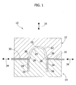
- the apparatus 10 comprises a first half-mould 12 and a second half-mould 14, which are mobile with respect to one another in a direction of opening/closing indicated by the arrow 16.
- the first and second half-moulds 12, 14 have respective active moulding surfaces 18, 20, which, in the closed position of the half-moulds 12, 14, define an injection-moulding cavity 22 ( Figure 1 ).
- the moulding apparatus 10 comprises a first slider 24 slidably housed in a seat 26 formed in the second half-mould 14.
- the first slider 24 is mobile with respect to the second half-mould 14 in a direction parallel to the direction of opening/closing 16 between a position of first injection and a position of second injection.
- the first slider 24 has an active surface 28 that delimits the moulding cavity 22 along a continuous perimetral edge.
- the moulding apparatus 10 moreover comprises a second slider 30 and a third slider 32, each of which is mobile in a direction 34 orthogonal to the direction of opening/closing 16.
- the second and third sliders 30, 32 are both mobile between a position of first injection and a position of second injection. In the position of first injection, the second and third sliders 30, 32 have respective ends 36 that penetrate within the moulding cavity 22.
- the ends 36 of the second and third sliders 30, 32 have the purpose of forming seats 38 set at a distance from one another in a longitudinal direction along the perimetral outer side edge 40 of the tank.
- Figure 1 shows the two half-moulds 12, 14 in the closed position.
- the first, second, and third sliders 24 are located in the respective positions of first injection.
- FIG. 1 shows the apparatus 10 at the end of this first injection.
- the cavity 22 is filled with a relatively stiff plastic material that forms the body 42 of the tank.
- the plastic material 42 is made to solidify by keeping the half-moulds 12, 14 in the closed position and the first slider 24, the second slider 30 and the third slider 32 in the position of first injection.
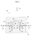
- the sliders 24, 30, 32 are brought into the respective positions of second injection, as represented in Figure 3 .
- the second-injection seat is formed, made up of two distinct and communicating portions 44, 38.
- the seat 44 is defined between the edge 28 of the first slider 24 and the facing edge 46 of the body of the tank 42.
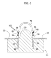
- the displacement of the second and third sliders 30, 32 into the position of second injection moreover forms the seats 38 ( Figure 8 ) on the longitudinal perimetral edge 40 of the body of the tank 42, said seats also concurring to form the second-injection seat.
- the seats 38 communicate with the seats 44 and, together with these make up the second-injection seat.
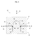
- an injectable elastomeric material is injected into the second-injection seat 44, 38.
- the material injected in this second injection adheres to the edge 46 of the body of the tank 42 and fills the seats 38.
- the elastomeric material injected in the seat 44 forms a continuous gasket 48 made of elastomeric material that extends continuously along the open edge of the body of the tank 42.
- Figure 7 shows an enlarged detail of the gasket made of elastomeric material 48 formed on the open edge of the body of the tank 42.
- the seats 38 enable mechanical engagement of the gasket 48 to the edge 40 of the body of the tank 42.
- holes 50 with axis parallel to the direction of opening/closing 16 of the half-moulds 12, 14.
- the holes 50 are preferably set in positions intermediate between successive seats 38.
- the holes 50 are made by pins (not illustrated) projecting from the edge 28 of the first slider. Said pins also make corresponding holes 52 in the gasket 48, as illustrated in Figures 7 and 10 .
- the solution according to the present invention differs considerably from a traditional process of bi-injection in so far as no movement of opening of the mould is necessary between the first and second injection steps, and replacements of mould parts are not necessary either. This enables a considerable reduction in the overall dimensions of the mould and in its cost (approximately 50%).
- the solution according to the invention moreover enables an equally considerable reduction in the dimensions and tonnage of the press associated to the moulding apparatus 10 to be obtained.
- a traditional press provided with a small satellite injector mounted directly on the mould is sufficient.
- the system according to the present invention as compared to the system of overmoulding described in the document No. US6238610 , in addition to being faster and less expensive, eliminates completely the risk of formations of cracks on the outer edge of the body of the tank. In fact, it is not necessary to exert pressure on the body of the tank with metal mould parts.
- the invention is not limited to the specific details illustrated by way of example and is applicable to tanks with bi-injected gaskets having any geometry of the profile of the gasket and of the seats 38.
Landscapes
- Engineering & Computer Science (AREA)
- Mechanical Engineering (AREA)
- Physics & Mathematics (AREA)
- Thermal Sciences (AREA)
- General Engineering & Computer Science (AREA)
- Manufacturing & Machinery (AREA)
- Injection Moulding Of Plastics Or The Like (AREA)
Priority Applications (1)
| Application Number | Priority Date | Filing Date | Title |
|---|---|---|---|
| EP08425111A EP2093040A1 (fr) | 2008-02-22 | 2008-02-22 | Procédé de fabrication d'un réservoir d'échangeur thermique et réservoir obtenu selon ledit procédé |
Applications Claiming Priority (1)
| Application Number | Priority Date | Filing Date | Title |
|---|---|---|---|
| EP08425111A EP2093040A1 (fr) | 2008-02-22 | 2008-02-22 | Procédé de fabrication d'un réservoir d'échangeur thermique et réservoir obtenu selon ledit procédé |
Publications (1)
| Publication Number | Publication Date |
|---|---|
| EP2093040A1 true EP2093040A1 (fr) | 2009-08-26 |
Family
ID=39590171
Family Applications (1)
| Application Number | Title | Priority Date | Filing Date |
|---|---|---|---|
| EP08425111A Withdrawn EP2093040A1 (fr) | 2008-02-22 | 2008-02-22 | Procédé de fabrication d'un réservoir d'échangeur thermique et réservoir obtenu selon ledit procédé |
Country Status (1)
| Country | Link |
|---|---|
| EP (1) | EP2093040A1 (fr) |
Cited By (5)
| Publication number | Priority date | Publication date | Assignee | Title |
|---|---|---|---|---|
| DE102013226434A1 (de) * | 2013-12-18 | 2015-06-18 | MAHLE Behr GmbH & Co. KG | Wärmeübertrager |
| DE102014101143A1 (de) | 2014-01-30 | 2015-07-30 | Halla Visteon Climate Control Corporation | Verfahren zur Herstellung eines Radiator- oder Ladeluftkühlerkastens |
| JP2016017722A (ja) * | 2014-07-11 | 2016-02-01 | 株式会社デンソー | ヘッダタンク部品及び熱交換器 |
| DE102022129758A1 (de) * | 2022-11-10 | 2024-05-16 | Audi Aktiengesellschaft | Verfahren zum Herstellen eines mehrschichtigen Mehrkomponentenbauteils |
| WO2025153316A1 (fr) * | 2024-01-19 | 2025-07-24 | Robert Bosch Gmbh | Dispositif de moulage par injection-compression et procédé de moulage par injection-compression pour produire une plaque bipolaire et un joint d'étanchéité s'étendant autour de la plaque bipolaire |
Citations (4)
| Publication number | Priority date | Publication date | Assignee | Title |
|---|---|---|---|---|
| US5246065A (en) * | 1990-12-21 | 1993-09-21 | Cadillac Rubber & Plastics, Inc. | Heat exchanger tank incorporating an overmolded gasket |
| JPH0631770A (ja) * | 1992-07-22 | 1994-02-08 | Hitachi Ltd | シール構造部付き筐体、成形用金型及びそれを用いた製造方法 |
| US6238610B1 (en) | 1995-05-02 | 2001-05-29 | Calsonic Kansei Corporation | Heat exchanger tank and method of producing the same |
| FR2824773A1 (fr) * | 2001-05-17 | 2002-11-22 | Renault | Procede de fabrication par moulage d'une piece composite en matiere plastique et en caoutchouc |
-
2008
- 2008-02-22 EP EP08425111A patent/EP2093040A1/fr not_active Withdrawn
Patent Citations (4)
| Publication number | Priority date | Publication date | Assignee | Title |
|---|---|---|---|---|
| US5246065A (en) * | 1990-12-21 | 1993-09-21 | Cadillac Rubber & Plastics, Inc. | Heat exchanger tank incorporating an overmolded gasket |
| JPH0631770A (ja) * | 1992-07-22 | 1994-02-08 | Hitachi Ltd | シール構造部付き筐体、成形用金型及びそれを用いた製造方法 |
| US6238610B1 (en) | 1995-05-02 | 2001-05-29 | Calsonic Kansei Corporation | Heat exchanger tank and method of producing the same |
| FR2824773A1 (fr) * | 2001-05-17 | 2002-11-22 | Renault | Procede de fabrication par moulage d'une piece composite en matiere plastique et en caoutchouc |
Cited By (6)
| Publication number | Priority date | Publication date | Assignee | Title |
|---|---|---|---|---|
| DE102013226434A1 (de) * | 2013-12-18 | 2015-06-18 | MAHLE Behr GmbH & Co. KG | Wärmeübertrager |
| EP2886991A1 (fr) * | 2013-12-18 | 2015-06-24 | MAHLE Behr GmbH & Co. KG | Caloporteur |
| DE102014101143A1 (de) | 2014-01-30 | 2015-07-30 | Halla Visteon Climate Control Corporation | Verfahren zur Herstellung eines Radiator- oder Ladeluftkühlerkastens |
| JP2016017722A (ja) * | 2014-07-11 | 2016-02-01 | 株式会社デンソー | ヘッダタンク部品及び熱交換器 |
| DE102022129758A1 (de) * | 2022-11-10 | 2024-05-16 | Audi Aktiengesellschaft | Verfahren zum Herstellen eines mehrschichtigen Mehrkomponentenbauteils |
| WO2025153316A1 (fr) * | 2024-01-19 | 2025-07-24 | Robert Bosch Gmbh | Dispositif de moulage par injection-compression et procédé de moulage par injection-compression pour produire une plaque bipolaire et un joint d'étanchéité s'étendant autour de la plaque bipolaire |
Similar Documents
| Publication | Publication Date | Title |
|---|---|---|
| JP6587855B2 (ja) | 射出成形方法および金型 | |
| EP2864095B1 (fr) | Procédé de moulage par injection pour la fabrication d'un élément d'habillage moulé par injection pour un véhicule automobile | |
| EP2093040A1 (fr) | Procédé de fabrication d'un réservoir d'échangeur thermique et réservoir obtenu selon ledit procédé | |
| CN102166811B (zh) | 注射成型用模具 | |
| US20100052209A1 (en) | Method of manufacturing a component for a vehicle interior | |
| US8215947B2 (en) | Molding die | |
| US20150353145A1 (en) | Floor made from plastic material for a motor vehicle with metal fittting inserts | |
| CN103640152B (zh) | 挡泥板模具及其注塑工艺 | |
| CN112677405A (zh) | 一种汽车格栅的双色注塑模具及双色成型方法 | |
| JP5158077B2 (ja) | 型内被覆成形用金型 | |
| US7938638B2 (en) | Mould for the injection-moulding a component comprising two portions which are composed of different materials | |
| CN108839305B (zh) | 一种用于制作拉丝薄膜的模具、方法及拉丝薄膜 | |
| WO1994021440A1 (fr) | Procede de moulage de pieces structurales en plastique | |
| CN101791840B (zh) | 塑料微流控芯片的型腔移动式射压成型方法 | |
| JP2005193634A (ja) | 射出成形体の製造方法とその金型装置 | |
| CN112829187B (zh) | 一种模内压缩双色注塑模具 | |
| CN102632850B (zh) | 车辆用保险杠及其成形方法 | |
| JP2021011029A (ja) | 成形構造体の製造方法及び成形構造体 | |
| JP2007030509A (ja) | 少なくとも1つのオーバーモールド部品を有するプラスチック材料製品の製造工程および製造装置 | |
| JP4051566B2 (ja) | 型内被覆成形方法及び型内被覆成形用金型 | |
| CN116690881B (zh) | 开模发泡模具的随行机构及开模发泡注塑方法 | |
| JP4049685B2 (ja) | 部分加飾成形品の成形方法 | |
| CN211389982U (zh) | U型盖条端部深槽抽芯脱模结构 | |
| CN201264341Y (zh) | 一种需侧抽芯的塑件的热流道注射成形模具 | |
| CN203622810U (zh) | 挡泥板模具 |
Legal Events
| Date | Code | Title | Description |
|---|---|---|---|
| PUAI | Public reference made under article 153(3) epc to a published international application that has entered the european phase |
Free format text: ORIGINAL CODE: 0009012 |
|
| AK | Designated contracting states |
Kind code of ref document: A1 Designated state(s): AT BE BG CH CY CZ DE DK EE ES FI FR GB GR HR HU IE IS IT LI LT LU LV MC MT NL NO PL PT RO SE SI SK TR |
|
| AX | Request for extension of the european patent |
Extension state: AL BA MK RS |
|
| 17P | Request for examination filed |
Effective date: 20100205 |
|
| 17Q | First examination report despatched |
Effective date: 20100326 |
|
| AKX | Designation fees paid |
Designated state(s): AT BE BG CH CY CZ DE DK EE ES FI FR GB GR HR HU IE IS IT LI LT LU LV MC MT NL NO PL PT RO SE SI SK TR |
|
| STAA | Information on the status of an ep patent application or granted ep patent |
Free format text: STATUS: THE APPLICATION IS DEEMED TO BE WITHDRAWN |
|
| 18D | Application deemed to be withdrawn |
Effective date: 20120823 |