EP2093319A2 - Dispositif d'appui pour un appareil ménager - Google Patents
Dispositif d'appui pour un appareil ménager Download PDFInfo
- Publication number
- EP2093319A2 EP2093319A2 EP09100128A EP09100128A EP2093319A2 EP 2093319 A2 EP2093319 A2 EP 2093319A2 EP 09100128 A EP09100128 A EP 09100128A EP 09100128 A EP09100128 A EP 09100128A EP 2093319 A2 EP2093319 A2 EP 2093319A2
- Authority
- EP
- European Patent Office
- Prior art keywords
- housing
- housing bottom
- base part
- domestic appliance
- arrangement according
- Prior art date
- Legal status (The legal status is an assumption and is not a legal conclusion. Google has not performed a legal analysis and makes no representation as to the accuracy of the status listed.)
- Withdrawn
Links
- 238000005406 washing Methods 0.000 claims description 26
- 238000001035 drying Methods 0.000 claims description 14
- 239000000463 material Substances 0.000 claims description 8
- 229910001220 stainless steel Inorganic materials 0.000 claims description 4
- 239000010935 stainless steel Substances 0.000 claims description 4
- 210000002414 leg Anatomy 0.000 description 35
- 230000033001 locomotion Effects 0.000 description 10
- 230000005540 biological transmission Effects 0.000 description 2
- 239000007769 metal material Substances 0.000 description 2
- 238000009987 spinning Methods 0.000 description 2
- 239000006096 absorbing agent Substances 0.000 description 1
- 230000009286 beneficial effect Effects 0.000 description 1
- 230000000295 complement effect Effects 0.000 description 1
- 238000013016 damping Methods 0.000 description 1
- 230000001419 dependent effect Effects 0.000 description 1
- 230000000694 effects Effects 0.000 description 1
- 239000013013 elastic material Substances 0.000 description 1
- 210000003414 extremity Anatomy 0.000 description 1
- 210000003746 feather Anatomy 0.000 description 1
- JEIPFZHSYJVQDO-UHFFFAOYSA-N iron(III) oxide Inorganic materials O=[Fe]O[Fe]=O JEIPFZHSYJVQDO-UHFFFAOYSA-N 0.000 description 1
- 239000002184 metal Substances 0.000 description 1
- 230000002787 reinforcement Effects 0.000 description 1
- 230000000284 resting effect Effects 0.000 description 1
- 230000035939 shock Effects 0.000 description 1
- 210000000689 upper leg Anatomy 0.000 description 1
Images

Classifications
-
- D—TEXTILES; PAPER
- D06—TREATMENT OF TEXTILES OR THE LIKE; LAUNDERING; FLEXIBLE MATERIALS NOT OTHERWISE PROVIDED FOR
- D06F—LAUNDERING, DRYING, IRONING, PRESSING OR FOLDING TEXTILE ARTICLES
- D06F37/00—Details specific to washing machines covered by groups D06F21/00 - D06F25/00
- D06F37/20—Mountings, e.g. resilient mountings, for the rotary receptacle, motor, tub or casing; Preventing or damping vibrations
-
- D—TEXTILES; PAPER
- D06—TREATMENT OF TEXTILES OR THE LIKE; LAUNDERING; FLEXIBLE MATERIALS NOT OTHERWISE PROVIDED FOR
- D06F—LAUNDERING, DRYING, IRONING, PRESSING OR FOLDING TEXTILE ARTICLES
- D06F37/00—Details specific to washing machines covered by groups D06F21/00 - D06F25/00
- D06F37/26—Casings; Tubs
Definitions
- the invention relates to a support arrangement for a damper of a household appliance and a washing and / or drying machine with such a support arrangement.
- dampers are arranged to hold the tub laundry drum group and to some extent dampen the movements and vibrations generated by the movement of the laundry drum.
- the upper end of the damper is usually fixed to the tub laundry drum group.
- the lower end of the damper is conventionally mounted directly on a support or cross member of the housing.
- the connection part for the damper is in this case usually formed integrally with the cross member or screwed or welded.
- the legs of the washing and / or drying machine are also usually attached to the cross member and the housing bottom.
- a vibration damping system which is arranged at a bearing connection of two housing parts of a washing machine.
- a cylindrical hollow upstanding pin which is arranged on a projection of a lower housing part, engages in a hole which is arranged on a projection of an upper housing part.
- a rubber ring is arranged between the two projections around the upstanding pin and is surrounded by a metal ring fixed to the housing.
- the EP 1 496 147 A1 discloses a fastening device for fixing a damper of a washing machine, which allows the attachment of the tub drum group of a washing machine to the housing of this machine in a simple form.
- the disclosed unitary carrier has two segments, with the first segment secured to the housing of the washing machine and hingedly coupled to the second segment with intermediate positioning of a flexible member of one of the heads of the damper.
- EP 1 382 733 B1 relates to a washing machine with a support frame, which accommodates the oscillating group, in which a laundry drum is arranged, in the form of a vibrating unit supported by a spring-damper system.
- the washing machine has a housing, which surrounds the oscillating group, and a measuring system for detecting the weight of the drum load in the form of at least one force transducer.
- the support frame is formed with the oscillating group as a unit decoupled from the housing.
- the housing is equipped with a separate housing frame, wherein the support frame is arranged in the operating state of the washing machine on the housing frame with the interposition of at least one force transducer. Due to the decoupling, no forces applied to the housing act on the oscillating group and thus on the load cells. However, vice versa forces, and thus vibrations, the vibrating group transferred to the housing.
- the object of the invention is to provide a support assembly for a damper of a household appliance, in particular for a washing and / or drying machine, which decouples the damper support dynamically from the housing so that the transmission of vibrations to the housing is minimized.
- a washing and / or drying machine is to be provided which dynamically decouples the damper assembly from the housing.
- the object is achieved by a household appliance Auflageran Aunt with a damper located within a housing for a non-contact with the housing component, wherein the support assembly further comprises a base and at least one leg connected to the base, wherein the leg and / or fixed to the leg connectable damper protrudes through an opening in a housing bottom into the interior of the housing, wherein the housing bottom rests loosely on the base.
- the vibrations that are caused in the non-contact component and reduced by the damper derived are not passed with the support arrangement according to the invention or only to a very small extent to the housing.
- the invention is based on the idea that vibrations that are passed on during the washing process and in particular during the spinning process in the oscillating group, which has the laundry drum, and to a lesser extent on the damper holding the oscillating group, not or only in the very be passed to the housing slightly.
- the damper is mounted such that it is not firmly coupled to the housing or housing bottom on which the legs of the machine are provided. Rather, a separate storage for the damper assembly is provided, which is at most by contact with the housing bottom in contact.
- a decoupling of damper support and housing is of great advantage, as it has the support arrangement according to the invention.
- two limbs connected to the base protrude through an opening in each case of the housing base into the interior space.
- a conventional trained damper end (damper strut) can be recorded and secured.
- dampers can be used together with the support assembly.
- the legs are made of stainless steel, so that in the relatively humid climate of a washing and / or drying machine can not develop rust on the supporting components.
- the base part of the support assembly is made of elastic, especially rubbery material.
- the base can also be made of plastic-like material to take advantage of the beneficial cushioning effect of the materials and minimize the transmission of vibration to the case back and thus the legs of the machine.
- the base may also include a core of metallic material on which preferably the legs are arranged.
- the stability of the base or the actual support of the damper is improved.
- a relative movement between the base and the housing bottom is reduced due to the higher weight of the base.
- an anti-rotation element for engaging in the housing bottom is arranged on the base, so that slipping and twisting of the housing relative to the assembly supported by the damper is prevented.
- the anti-rotation element for example a plurality of bolts, on the housing bottom side facing the base, i. So opposite the case back, arranged. These bolts engage in arranged in the housing bottom holes with little play.
- two cuts are placed in the base.
- the incisions extend continuously over the entire depth and, starting from the side adjacent to the housing bottom, between one third and two thirds of the total height.
- the legs with the connected or to be connected damper are preferably arranged in this embodiment on the base between the two incisions.
- the base part is formed by at least two sections.
- the portions include a middle portion where the damper joins the base and at least one outer portion formed in contact with the outside of the case bottom.
- the base has the shape of a disc with the middle section in its interior.
- the at least two sections are separated by an incision in the depth of the base starting from the side adjacent to the outside of the housing bottom.
- the surface of the middle section, where the thighs are located, begins where the cuts end, though not mandatory must be the case, and lies below the outside of the housing bottom with this contactless. Therefore, the housing bottom is supported on the outer sections.
- the anti-rotation element is arranged on the outer portion.
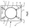
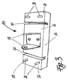
- the legs 18 are arranged at the central portion 22 of the formed by the incisions 20 three regions 22, 24, 26, the legs 18 are arranged.
- the two outer portions 24, 26 are each two anti-rotation elements 29, for example, bolts 28, preferably made of stainless steel, respectively.
- the housing bottom 10 each have holes which are slightly larger in diameter than the bolts 28, so that the bolt 28 (not shown) can engage with some movement in the holes.
- the legs 18 protrude through openings or slots 30 in the housing base 10 into the interior of the housing of the washing and / or drying machine.
- Either a separate slot 30 may be provided for each leg 18, or alternatively a correspondingly sized slot 30 may be provided together for both legs 18.
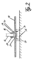
- the housing bottom 10 is loose and thus decoupled on the base 16.
- the base 16 is held against rotation in its horizontal position by the bolt 28. The play of movement of the pin 28 of the rotation is set so that at the maximum possible rotation of the base 16, the legs 18 do not come into contact with the edges of the slots 30 and thus with the housing bottom 10.
- the housing is supported by casings 32 mounted on the caseback.
- the damper leg 12 can be attached to the legs 18, for example by means of a locked pin 34 or by means of a screw each made of stainless steel.
- the anti-rotation element 29 may be formed on the underside of the housing bottom 10.
- bolts that are either screwed, welded or integrally formed with the housing bottom, engage in complementary holes in the outer portions 24, 26 of the base 16.
- projections may also be formed on the underside of the housing bottom 10.
- the projections may be welded complementarily to the corners of the base 16 on the housing bottom 10 and thereby the lateral movement of the housing bottom 10 relative to the support 14 in each of the four directions limit. The resulting motion play also allows no contact in each case between the leg 18 and the slot 30 in the housing bottom 10th
- the housing bottom has only one slot 30 through which the single leg protrudes.
- the shock absorber leg must then be designed accordingly for a non-positive connection.
- connection arrangement of the leg (s) 18 with the damper 12 may also be provided below the housing bottom 10.
- connection arrangement of the central portion 22 of the base 16 must be made lower than the two outer portions 24, 26 so that when resting the housing bottom 10 on the base 16, the connection assembly can be arranged without contact with the housing 2.
- vibrations are conducted into the damper due to the movement of the laundry drum.
- the vibrations are reduced, and the remaining vibrations are passed through the support assembly on the strut 12 via legs 18 in a base 16.
- the base 16 made of at least partially elastic material further dampens the vibrations and releases them into the ground.
- the module is dynamically decoupled from the housing. In the area of the support arrangement, the housing bottom 10 loosely rests on the base part 16. The prevailing in the base vibration is therefore not or only slightly delivered to the housing bottom 10 and due to the cuts 20 in the base 16.
- the movement of the security against rotation is designed such that a contact between the damper 12 / leg 18 and the edge of the slot 30 in the housing bottom 10 is excluded.
- the base part 16 is formed by at least two sections 22, 24, 26, a middle section 22, where the damper 12 is attached to the base 16 connects, and at least one outer portion 24, 26 formed in contact with the outside of the housing bottom 10.
- the base 16 has the shape of a disc with the central portion 22 in its interior.
- the at least two sections are separated by a recess 20 in the depth of the base part 16, starting from the voltage applied to the outside of the housing bottom 10 side.
- the surface of the central portion 22, where the legs 18 are located begins where the sipes end, though not necessarily, and is located below the outside of the housing bottom 10 with this contactless. Therefore, the housing bottom 10 is supported on the outer portions 24, 26 from.
- the anti-rotation element 29 is arranged on the outer portion 24, 26.
Landscapes
- Engineering & Computer Science (AREA)
- Textile Engineering (AREA)
- Main Body Construction Of Washing Machines And Laundry Dryers (AREA)
- Vibration Prevention Devices (AREA)
Applications Claiming Priority (1)
| Application Number | Priority Date | Filing Date | Title |
|---|---|---|---|
| ES200800613A ES2330292B1 (es) | 2008-02-22 | 2008-02-22 | Disposicion de apoyo para un aparato domestico. |
Publications (2)
| Publication Number | Publication Date |
|---|---|
| EP2093319A2 true EP2093319A2 (fr) | 2009-08-26 |
| EP2093319A3 EP2093319A3 (fr) | 2015-08-12 |
Family
ID=40671413
Family Applications (1)
| Application Number | Title | Priority Date | Filing Date |
|---|---|---|---|
| EP09100128.9A Withdrawn EP2093319A3 (fr) | 2008-02-22 | 2009-02-19 | Dispositif d'appui pour un appareil ménager |
Country Status (2)
| Country | Link |
|---|---|
| EP (1) | EP2093319A3 (fr) |
| ES (1) | ES2330292B1 (fr) |
Cited By (4)
| Publication number | Priority date | Publication date | Assignee | Title |
|---|---|---|---|---|
| WO2013113688A1 (fr) * | 2012-01-31 | 2013-08-08 | Siemens Aktiengesellschaft | Procédé permettant de réduire les oscillations résonantes d'un ensemble rotor |
| ITTO20121010A1 (it) * | 2012-11-20 | 2014-05-21 | Indesit Co Spa | Macchina lavabiancheria di uso domestico comprendente una spina per l'accoppiamento di almeno un elemento ammortizzatore ad un gruppo oscillante, e relativa spina. |
| EP2735633A1 (fr) * | 2012-11-20 | 2014-05-28 | Indesit Company S.p.A. | Machine à laver le linge à usage ménager comprenant une broche pour coupler au moins un élément d'absorption de chocs pour un ensemble oscillant et son axe |
| CN116716711A (zh) * | 2023-06-19 | 2023-09-08 | Tcl家用电器(合肥)有限公司 | 洗衣机控制方法、装置、洗衣机及计算机可读存储介质 |
Citations (3)
| Publication number | Priority date | Publication date | Assignee | Title |
|---|---|---|---|---|
| EP0933463A1 (fr) | 1998-02-02 | 1999-08-04 | Balay S.A. | Dispositif pour fixer un amortisseur à la cuve d'une machine à laver |
| EP1496147A1 (fr) | 2003-07-11 | 2005-01-12 | BSH Bosch und Siemens Hausgeräte GmbH | Dispositif de fixation pour amortisseur d'une machine à laver |
| EP1382733B1 (fr) | 2002-07-17 | 2007-05-23 | Miele & Cie. KG | Machine à laver avec groupe de lavage |
Family Cites Families (7)
| Publication number | Priority date | Publication date | Assignee | Title |
|---|---|---|---|---|
| US4262870A (en) * | 1979-07-11 | 1981-04-21 | Whirlpool Corporation | Retractable self-leveling support assembly for automatic washer |
| DE3538973A1 (de) * | 1985-11-02 | 1987-05-14 | Bauknecht Hausgeraete | Waschmaschine |
| IT213423Z2 (it) * | 1987-11-04 | 1989-11-27 | Pirelli | Dispositivo ammortizzatore per macchina lavabiancheria. |
| US5257516A (en) * | 1992-06-02 | 1993-11-02 | Raytheon Company | Washing machine |
| DE19615010A1 (de) * | 1996-04-16 | 1997-10-23 | Suspa Compart Ag | Reibungsdämpfer, insbesondere für Waschmaschinen mit Schleudergang |
| IT1294130B1 (it) * | 1997-05-15 | 1999-03-22 | Electrolux Zanussi Elettrodome | Metodo per realizzare uno smorzamento attivo delle vibrazioni dovute al gruppo lavante e macchina lavatrice per attuare tale |
| KR101084117B1 (ko) * | 2004-06-01 | 2011-11-18 | 엘지전자 주식회사 | 드럼세탁기의 베이스구조 |
-
2008
- 2008-02-22 ES ES200800613A patent/ES2330292B1/es not_active Revoked
-
2009
- 2009-02-19 EP EP09100128.9A patent/EP2093319A3/fr not_active Withdrawn
Patent Citations (3)
| Publication number | Priority date | Publication date | Assignee | Title |
|---|---|---|---|---|
| EP0933463A1 (fr) | 1998-02-02 | 1999-08-04 | Balay S.A. | Dispositif pour fixer un amortisseur à la cuve d'une machine à laver |
| EP1382733B1 (fr) | 2002-07-17 | 2007-05-23 | Miele & Cie. KG | Machine à laver avec groupe de lavage |
| EP1496147A1 (fr) | 2003-07-11 | 2005-01-12 | BSH Bosch und Siemens Hausgeräte GmbH | Dispositif de fixation pour amortisseur d'une machine à laver |
Cited By (4)
| Publication number | Priority date | Publication date | Assignee | Title |
|---|---|---|---|---|
| WO2013113688A1 (fr) * | 2012-01-31 | 2013-08-08 | Siemens Aktiengesellschaft | Procédé permettant de réduire les oscillations résonantes d'un ensemble rotor |
| ITTO20121010A1 (it) * | 2012-11-20 | 2014-05-21 | Indesit Co Spa | Macchina lavabiancheria di uso domestico comprendente una spina per l'accoppiamento di almeno un elemento ammortizzatore ad un gruppo oscillante, e relativa spina. |
| EP2735633A1 (fr) * | 2012-11-20 | 2014-05-28 | Indesit Company S.p.A. | Machine à laver le linge à usage ménager comprenant une broche pour coupler au moins un élément d'absorption de chocs pour un ensemble oscillant et son axe |
| CN116716711A (zh) * | 2023-06-19 | 2023-09-08 | Tcl家用电器(合肥)有限公司 | 洗衣机控制方法、装置、洗衣机及计算机可读存储介质 |
Also Published As
| Publication number | Publication date |
|---|---|
| ES2330292B1 (es) | 2010-09-16 |
| ES2330292A1 (es) | 2009-12-07 |
| EP2093319A3 (fr) | 2015-08-12 |
Similar Documents
| Publication | Publication Date | Title |
|---|---|---|
| DE102007026130B4 (de) | Mechanische Vorrichtung zum Waschen/Trocknen | |
| DE69813726T2 (de) | Aufhängevorrichtung für Waschmaschine | |
| EP1754908B1 (fr) | Amortisseur | |
| EP1637640B1 (fr) | Amortisseur | |
| EP0806514B1 (fr) | Amortisseur à friction, en particulier pour machines à laver avec phase d'essorage | |
| DE3609149C2 (fr) | ||
| DE102006001437A1 (de) | Gehäuse für eine frontbeschickbare Wäschebehandlungsmaschine | |
| EP2601426B1 (fr) | Amortisseur de vibrations de torsion doté d'un pendule à deux bras | |
| DE69918969T2 (de) | Motorlager | |
| DE4215780C2 (de) | Transportsicherung für das schwingende Systems einer Haushaltswaschmaschine | |
| DE3884759T2 (de) | Trommelantriebsvorrichtung zur Verwendung in einem Spielautomaten. | |
| EP0230685B1 (fr) | Fixation de l'amortisseur dans une machine à laver | |
| EP2301385B1 (fr) | Entraînement pour meuble | |
| AT509635B1 (de) | Anordnung zur lagerung einer baugruppe an einer kraftfahrzeugkarosserie | |
| EP0318109B1 (fr) | Cuve pour machines à laver | |
| DE102007049908A1 (de) | Spannvorrichtung für das Zufmittel eines Zugmitteltriebes | |
| DE2534650A1 (de) | Schwingungsfaehige abstuetzung fuer trommelwaschmaschinen mit horizontaler drehachse | |
| EP3569952B1 (fr) | Module de base permettant de recevoir un compresseur et appareil électroménager | |
| WO2008080826A1 (fr) | Unité d'entraînement pour un sèche-linge à usage domestique | |
| DE9206506U1 (de) | Einrichtung zur Fixierung des schwingenden Systems einer Haushaltsmaschine | |
| DE666946C (de) | Waescheschleuder | |
| DE69802050T2 (de) | Elastische Aufhängevorrichtung für Waschmaschine | |
| DE112006003882T5 (de) | Trommelwaschmaschine E | |
| DE4026549C2 (de) | Von vorn beschickbare Waschmaschine | |
| DE10011739B4 (de) | Spannvorrichtung eines Ketten- oder Riementriebs |
Legal Events
| Date | Code | Title | Description |
|---|---|---|---|
| PUAI | Public reference made under article 153(3) epc to a published international application that has entered the european phase |
Free format text: ORIGINAL CODE: 0009012 |
|
| AK | Designated contracting states |
Kind code of ref document: A2 Designated state(s): AT BE BG CH CY CZ DE DK EE ES FI FR GB GR HR HU IE IS IT LI LT LU LV MC MK MT NL NO PL PT RO SE SI SK TR |
|
| AX | Request for extension of the european patent |
Extension state: AL BA RS |
|
| RAP1 | Party data changed (applicant data changed or rights of an application transferred) |
Owner name: BSH HAUSGERAETE GMBH |
|
| PUAL | Search report despatched |
Free format text: ORIGINAL CODE: 0009013 |
|
| AK | Designated contracting states |
Kind code of ref document: A3 Designated state(s): AT BE BG CH CY CZ DE DK EE ES FI FR GB GR HR HU IE IS IT LI LT LU LV MC MK MT NL NO PL PT RO SE SI SK TR |
|
| AX | Request for extension of the european patent |
Extension state: AL BA RS |
|
| RIC1 | Information provided on ipc code assigned before grant |
Ipc: D06F 37/26 20060101ALI20150706BHEP Ipc: D06F 37/20 20060101AFI20150706BHEP |
|
| 17P | Request for examination filed |
Effective date: 20160212 |
|
| RBV | Designated contracting states (corrected) |
Designated state(s): AT BE BG CH CY CZ DE DK EE ES FI FR GB GR HR HU IE IS IT LI LT LU LV MC MK MT NL NO PL PT RO SE SI SK TR |
|
| AKX | Designation fees paid |
Designated state(s): AT BE BG CH CY CZ DE DK EE ES FI FR GB GR HR HU IE IS IT LI LT LU LV MC MK MT NL NO PL PT RO SE SI SK TR |
|
| AXX | Extension fees paid |
Extension state: AL Extension state: BA Extension state: RS |
|
| 17Q | First examination report despatched |
Effective date: 20160616 |
|
| GRAP | Despatch of communication of intention to grant a patent |
Free format text: ORIGINAL CODE: EPIDOSNIGR1 |
|
| INTG | Intention to grant announced |
Effective date: 20160824 |
|
| STAA | Information on the status of an ep patent application or granted ep patent |
Free format text: STATUS: THE APPLICATION IS DEEMED TO BE WITHDRAWN |
|
| 18D | Application deemed to be withdrawn |
Effective date: 20170104 |