EP2093328A2 - Dispositif de drainage pour ponts à connexion variable - Google Patents
Dispositif de drainage pour ponts à connexion variable Download PDFInfo
- Publication number
- EP2093328A2 EP2093328A2 EP09002165A EP09002165A EP2093328A2 EP 2093328 A2 EP2093328 A2 EP 2093328A2 EP 09002165 A EP09002165 A EP 09002165A EP 09002165 A EP09002165 A EP 09002165A EP 2093328 A2 EP2093328 A2 EP 2093328A2
- Authority
- EP
- European Patent Office
- Prior art keywords
- frame
- bridge
- tray
- drainer
- grating
- Prior art date
- Legal status (The legal status is an assumption and is not a legal conclusion. Google has not performed a legal analysis and makes no representation as to the accuracy of the status listed.)
- Withdrawn
Links
- 238000004078 waterproofing Methods 0.000 claims abstract description 12
- 238000009413 insulation Methods 0.000 claims description 4
- 239000004575 stone Substances 0.000 claims description 4
- 230000032258 transport Effects 0.000 claims 1
- XLYOFNOQVPJJNP-UHFFFAOYSA-N water Substances O XLYOFNOQVPJJNP-UHFFFAOYSA-N 0.000 abstract description 3
- 238000007789 sealing Methods 0.000 description 1
Images


Classifications
-
- E—FIXED CONSTRUCTIONS
- E01—CONSTRUCTION OF ROADS, RAILWAYS, OR BRIDGES
- E01D—CONSTRUCTION OF BRIDGES, ELEVATED ROADWAYS OR VIADUCTS; ASSEMBLY OF BRIDGES
- E01D19/00—Structural or constructional details of bridges
- E01D19/08—Damp-proof or other insulating layers; Drainage arrangements or devices ; Bridge deck surfacings
- E01D19/086—Drainage arrangements or devices
Definitions
- the invention refers to a bridge drainer, variably fitted for diverse bridge floor types to be used in old stone bridges advantageously.
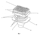
- the drainer consists of four main parts: a tray, a pot, a frame with corner bevels, and a grating.
- a tray In the rectangular tray there is an outlet hole in which the rectangular pot is located with a circular hole to fasten a dirt strainer.
- a frame In the pot there is a frame in which a grating is inserted of which the shape is identical with that of the frame.
- the grating ribs are shortened in the central part and at one shorter grating side the rib is fitted with a lock meshing with a hollow in the frame. At the second shorter grating side the rib is provided with hinge catches with a permanently attached rod by means of which the grating is joined to the frame permanently on the knuckle joint principle.
- the angle of rotation of the permanently joined grating-and-frame set is limited in the extent of ⁇ 15° and said set can be shifted by 60 mm at most in transversal and/or longitudinal direction.
- the corner bevels are shaped so that they bear against the longer inner pot wall with the set adjusted to the limit of 15° at most.
- the funnel bottom part passes into the central hemispheric part with the bottom brim bevelled with the inclination that is parallel with that of the funnel wall and bevelled at the same time conformably with the top brim of the rotary part.
- This has hemispheric shape too from which the smooth pipeline end goes out on the bottom part.
- a circular reduction is fastened rigidly with a central hole fitted with a hollow on the circumference to fasten the segment top of which the part is identical with the hollow as for the shape.
- the bridge drainer consists of a tray in its bottom part.
- the tray outlet is joined to the bridge draining system and the tray top part is formed as a collar.
- On this collar the waterproofing is placed on which the frame-and-grating set is located.
- the waterproofing clamping between the collar and the frame provides its horizontal connection to prevent water from leaking into the bridge structure bottom part.
- the grating is joined with the frame by means of a hinge that is located so that the junction is perpendicular to the traffic direction on the bridge.
- In the frame there is a circular opening on which the limiting lugs are made on the circumference to limit the rotational rectification where the lugs have the shape of opposite located sections rotated partially by 45° against the frame vertical axis.
- the frame bottom surface is provided with grooves to drain off the bridge insulation surface.
- a variant solution is based on the possibility to set the bridge drainer for diverse thick bridge floor types which is provided by corresponding combination of dimensional variants of rectification rings inserted between the waterproofing and the frame.
- the rectification ring has circular shape with conical top and bottom surfaces.
- the rectification ring bottom surface is identically shaped as the frame bottom surface and the top part of the rectification ring has the same shape as the collar top part.
- the waterproofing is clamped between the rectification ring and the tray collar.
- a tray with a vertical outlet or that with a side outlet can be used. Due to this variability the bridge drainers can be used both on up-to-date bridges and on old ones where the draining can be led into stone gargoyles.
- a bridge drainer has been made according the proposed solution.
- the bridge drainer bottom part consists of the tray 3, provided with the side outlet 3B in this case.
- the waterproofing 11 is fitted in a waterproof way to prevent water from leaking into the bridge structure bottom parts from the bridge floor surface.
- the surface of the waterproofing 11 is drained into the bridge drainer by means of four grooves 9 .
- the number and thickness of the rectification rings 4 enable to set the bridge drainer for required thickness of the bridge floor layers set. In this case this rectification ring 4 is 25 mm thick.
- the top part of the bridge drainer is placed consisting of the frame 2 with the grating 1 that is attached by means of the hinge 5 to the frame 2 and secured with the lock 8 .
- the device is located so that the axial junction of the hinge may be perpendicular to the traffic direction on the bridge.
- Two limiting lugs 10 are made on the circumference of the circular opening in the frame 2 . They are formed as opposite sectors rotated by 45° against the vertical axis of the frame 2 .
- the bridge drainer can have the vertical outlet 3A or the side outlet 3B . Thanks to its variability, based on arbitrary number of rings of diverse thickness and two possible outlet variants, this arrangement can be used advantageously for old stone bridges where the outlet can be led in original gargoyles.
Landscapes
- Engineering & Computer Science (AREA)
- Architecture (AREA)
- Civil Engineering (AREA)
- Structural Engineering (AREA)
- Building Environments (AREA)
- Sink And Installation For Waste Water (AREA)
- Connector Housings Or Holding Contact Members (AREA)
- Details Of Rigid Or Semi-Rigid Containers (AREA)
Applications Claiming Priority (1)
| Application Number | Priority Date | Filing Date | Title |
|---|---|---|---|
| CZ20080090A CZ200890A3 (cs) | 2008-02-19 | 2008-02-19 | Mostní odvodnovac s variabilním napojením |
Publications (2)
| Publication Number | Publication Date |
|---|---|
| EP2093328A2 true EP2093328A2 (fr) | 2009-08-26 |
| EP2093328A3 EP2093328A3 (fr) | 2011-05-18 |
Family
ID=40599268
Family Applications (1)
| Application Number | Title | Priority Date | Filing Date |
|---|---|---|---|
| EP09002165A Withdrawn EP2093328A3 (fr) | 2008-02-19 | 2009-02-17 | Dispositif de drainage pour ponts à connexion variable |
Country Status (2)
| Country | Link |
|---|---|
| EP (1) | EP2093328A3 (fr) |
| CZ (1) | CZ200890A3 (fr) |
Cited By (5)
| Publication number | Priority date | Publication date | Assignee | Title |
|---|---|---|---|---|
| KR101197670B1 (ko) | 2012-06-29 | 2012-11-07 | 추용대 | 교량용 집수구 및 그 시공방법 |
| DE102014119087B3 (de) * | 2014-12-18 | 2016-05-12 | ACO Severin Ahlmann GmbH & Co Kommanditgesellschaft | Oberteil eines Ablaufes für eine Oberflächenentwässerung |
| JP2018119299A (ja) * | 2017-01-24 | 2018-08-02 | 日本車輌製造株式会社 | 付着強化型排水桝 |
| JP2018131823A (ja) * | 2017-02-16 | 2018-08-23 | 株式会社ダイクレ | 橋梁用排水桝の取付構造 |
| CN116988373A (zh) * | 2023-08-09 | 2023-11-03 | 北京市市政工程设计研究总院有限公司 | 一种排水口及施工方法 |
Families Citing this family (1)
| Publication number | Priority date | Publication date | Assignee | Title |
|---|---|---|---|---|
| CZ2011443A3 (cs) * | 2011-07-21 | 2012-09-05 | Ceské vysoké ucení technické v Praze Fakulta stavební | Hrncový odvodnovac pro betonové lávky pro peší |
Citations (2)
| Publication number | Priority date | Publication date | Assignee | Title |
|---|---|---|---|---|
| CZ233098A3 (cs) | 1998-07-24 | 2000-02-16 | Petr Ing. Vlček | Odvodňovací odtoková část mostní vpusti |
| CZ20021544A3 (en) | 2002-05-02 | 2004-03-17 | Vlček Spol. S R. O. | Pivoted bridge drainer |
Family Cites Families (5)
| Publication number | Priority date | Publication date | Assignee | Title |
|---|---|---|---|---|
| DD16592A1 (de) * | 1955-11-18 | 1959-03-24 | Loeffler Walter | Vorrichtung zur Nivellierung eines Bodenentwässerungskörpers mit der Fussbodenoberfläche |
| CH442399A (de) * | 1966-05-23 | 1967-08-31 | Streicher Fa M | Brückenablauf und Verfahren zur Herstellung des Ablaufes |
| DE6808886U (de) * | 1968-11-01 | 1969-10-16 | Passavant Werke | Ablauf, insbesondere strassen- oder brueckenablauf |
| DE3902791C1 (en) * | 1989-01-31 | 1990-06-13 | Passavant-Werke Ag, 6209 Aarbergen, De | Road gulley, in particular bridge gulley |
| DE9003409U1 (de) * | 1990-03-23 | 1990-05-31 | Passavant-Werke AG, 6209 Aarbergen | Decken-, Boden- oder Badablauf |
-
2008
- 2008-02-19 CZ CZ20080090A patent/CZ200890A3/cs unknown
-
2009
- 2009-02-17 EP EP09002165A patent/EP2093328A3/fr not_active Withdrawn
Patent Citations (2)
| Publication number | Priority date | Publication date | Assignee | Title |
|---|---|---|---|---|
| CZ233098A3 (cs) | 1998-07-24 | 2000-02-16 | Petr Ing. Vlček | Odvodňovací odtoková část mostní vpusti |
| CZ20021544A3 (en) | 2002-05-02 | 2004-03-17 | Vlček Spol. S R. O. | Pivoted bridge drainer |
Cited By (5)
| Publication number | Priority date | Publication date | Assignee | Title |
|---|---|---|---|---|
| KR101197670B1 (ko) | 2012-06-29 | 2012-11-07 | 추용대 | 교량용 집수구 및 그 시공방법 |
| DE102014119087B3 (de) * | 2014-12-18 | 2016-05-12 | ACO Severin Ahlmann GmbH & Co Kommanditgesellschaft | Oberteil eines Ablaufes für eine Oberflächenentwässerung |
| JP2018119299A (ja) * | 2017-01-24 | 2018-08-02 | 日本車輌製造株式会社 | 付着強化型排水桝 |
| JP2018131823A (ja) * | 2017-02-16 | 2018-08-23 | 株式会社ダイクレ | 橋梁用排水桝の取付構造 |
| CN116988373A (zh) * | 2023-08-09 | 2023-11-03 | 北京市市政工程设计研究总院有限公司 | 一种排水口及施工方法 |
Also Published As
| Publication number | Publication date |
|---|---|
| EP2093328A3 (fr) | 2011-05-18 |
| CZ200890A3 (cs) | 2009-09-02 |
Similar Documents
| Publication | Publication Date | Title |
|---|---|---|
| EP2093328A2 (fr) | Dispositif de drainage pour ponts à connexion variable | |
| US6269495B1 (en) | Adjustable floor drain apparatus | |
| US11319698B2 (en) | Shower drain with a clamping collar | |
| US20140116527A1 (en) | Rough-In Adapter | |
| US20100319281A1 (en) | Floor Through Assembly with Adjustable Drain | |
| US20140131996A1 (en) | Water Drainage System | |
| US11208795B2 (en) | Floor drain for draining water from a walk-in floor into a sewage pipe | |
| SE500711C2 (sv) | Anordning vid golvbrunn | |
| JP6721305B2 (ja) | 排水システム | |
| EP1811093A1 (fr) | Dispositif de drainage adaptable à la pente du sol | |
| EP3686363B1 (fr) | Ecoulement de sol carrelé | |
| JP6822631B2 (ja) | 排水配管及び排水配管の施工方法 | |
| KR101336978B1 (ko) | 파이프 연결밴드 | |
| EP1141495A1 (fr) | Base d'egout | |
| KR200394253Y1 (ko) | 맨홀뚜껑 몸체의 받침판 | |
| KR200462635Y1 (ko) | 배수관 연결이 용이한 교량의 배수처리장치 | |
| RU2546857C2 (ru) | Регулируемый по высоте половой водослив с соединительным кольцом, снабженным каналом для отвода воды | |
| EP1194661B1 (fr) | Toiture ou bardage formé(e) par juxtapostion de plaques ondulées, avec une couverture ou un appareil fixé dessus | |
| KR100943942B1 (ko) | 밀봉소켓 조립체 | |
| KR100732475B1 (ko) | 관로의 방향변경이 가능한 맨홀의 관 결합구조 | |
| JPH05302412A (ja) | 軒樋と竪樋の接続構造 | |
| JP6913896B2 (ja) | 養生蓋 | |
| AU2014240279B2 (en) | A Roof Overflow | |
| JP7518612B2 (ja) | 排水用ドレン及び排水用ドレンセット | |
| NO316562B1 (no) | Klemring for å feste et gulvbelegg til et gulvsluk |
Legal Events
| Date | Code | Title | Description |
|---|---|---|---|
| PUAI | Public reference made under article 153(3) epc to a published international application that has entered the european phase |
Free format text: ORIGINAL CODE: 0009012 |
|
| AK | Designated contracting states |
Kind code of ref document: A2 Designated state(s): AT BE BG CH CY CZ DE DK EE ES FI FR GB GR HR HU IE IS IT LI LT LU LV MC MK MT NL NO PL PT RO SE SI SK TR |
|
| AX | Request for extension of the european patent |
Extension state: AL BA RS |
|
| PUAL | Search report despatched |
Free format text: ORIGINAL CODE: 0009013 |
|
| AK | Designated contracting states |
Kind code of ref document: A3 Designated state(s): AT BE BG CH CY CZ DE DK EE ES FI FR GB GR HR HU IE IS IT LI LT LU LV MC MK MT NL NO PL PT RO SE SI SK TR |
|
| AX | Request for extension of the european patent |
Extension state: AL BA RS |
|
| AKY | No designation fees paid | ||
| REG | Reference to a national code |
Ref country code: DE Ref legal event code: R108 |
|
| REG | Reference to a national code |
Ref country code: DE Ref legal event code: R108 Effective date: 20120125 |
|
| STAA | Information on the status of an ep patent application or granted ep patent |
Free format text: STATUS: THE APPLICATION IS DEEMED TO BE WITHDRAWN |
|
| 18D | Application deemed to be withdrawn |
Effective date: 20111119 |