EP2093338B1 - Stabtragwerk zur Bildung eines Rahmens, umfassend mehrere Knoten und die Knoten verbindende Stäbe - Google Patents
Stabtragwerk zur Bildung eines Rahmens, umfassend mehrere Knoten und die Knoten verbindende Stäbe Download PDFInfo
- Publication number
- EP2093338B1 EP2093338B1 EP09006105A EP09006105A EP2093338B1 EP 2093338 B1 EP2093338 B1 EP 2093338B1 EP 09006105 A EP09006105 A EP 09006105A EP 09006105 A EP09006105 A EP 09006105A EP 2093338 B1 EP2093338 B1 EP 2093338B1
- Authority
- EP
- European Patent Office
- Prior art keywords
- lattice framework
- framework according
- rod
- flute
- elements
- Prior art date
- Legal status (The legal status is an assumption and is not a legal conclusion. Google has not performed a legal analysis and makes no representation as to the accuracy of the status listed.)
- Not-in-force
Links
- 239000004567 concrete Substances 0.000 claims description 6
- 238000013016 damping Methods 0.000 claims description 5
- 241000826860 Trapezium Species 0.000 claims description 2
- 238000004026 adhesive bonding Methods 0.000 claims description 2
- 239000000463 material Substances 0.000 claims description 2
- 239000011150 reinforced concrete Substances 0.000 abstract 1
- 230000007704 transition Effects 0.000 abstract 1
- 229910000831 Steel Inorganic materials 0.000 description 3
- 239000010959 steel Substances 0.000 description 3
- 239000011372 high-strength concrete Substances 0.000 description 2
- 239000002184 metal Substances 0.000 description 2
- 230000015572 biosynthetic process Effects 0.000 description 1
- 238000010276 construction Methods 0.000 description 1
- 238000005516 engineering process Methods 0.000 description 1
- 239000003822 epoxy resin Substances 0.000 description 1
- 230000005284 excitation Effects 0.000 description 1
- 230000010355 oscillation Effects 0.000 description 1
- 239000004033 plastic Substances 0.000 description 1
- 229920000647 polyepoxide Polymers 0.000 description 1
- 230000002787 reinforcement Effects 0.000 description 1
- 230000035939 shock Effects 0.000 description 1
- 239000007787 solid Substances 0.000 description 1
- 238000005406 washing Methods 0.000 description 1
- 239000002023 wood Substances 0.000 description 1
Images


Classifications
-
- F—MECHANICAL ENGINEERING; LIGHTING; HEATING; WEAPONS; BLASTING
- F16—ENGINEERING ELEMENTS AND UNITS; GENERAL MEASURES FOR PRODUCING AND MAINTAINING EFFECTIVE FUNCTIONING OF MACHINES OR INSTALLATIONS; THERMAL INSULATION IN GENERAL
- F16B—DEVICES FOR FASTENING OR SECURING CONSTRUCTIONAL ELEMENTS OR MACHINE PARTS TOGETHER, e.g. NAILS, BOLTS, CIRCLIPS, CLAMPS, CLIPS OR WEDGES; JOINTS OR JOINTING
- F16B12/00—Jointing of furniture or the like, e.g. hidden from exterior
- F16B12/44—Leg joints; Corner joints
-
- A—HUMAN NECESSITIES
- A47—FURNITURE; DOMESTIC ARTICLES OR APPLIANCES; COFFEE MILLS; SPICE MILLS; SUCTION CLEANERS IN GENERAL
- A47B—TABLES; DESKS; OFFICE FURNITURE; CABINETS; DRAWERS; GENERAL DETAILS OF FURNITURE
- A47B47/00—Cabinets, racks or shelf units, characterised by features related to dismountability or building-up from elements
- A47B47/0008—Three-dimensional corner connectors, the legs thereof being received within hollow, elongated frame members
-
- D—TEXTILES; PAPER
- D06—TREATMENT OF TEXTILES OR THE LIKE; LAUNDERING; FLEXIBLE MATERIALS NOT OTHERWISE PROVIDED FOR
- D06F—LAUNDERING, DRYING, IRONING, PRESSING OR FOLDING TEXTILE ARTICLES
- D06F39/00—Details of washing machines not specific to a single type of machines covered by groups D06F9/00 - D06F27/00
- D06F39/12—Casings; Tubs
-
- E—FIXED CONSTRUCTIONS
- E04—BUILDING
- E04B—GENERAL BUILDING CONSTRUCTIONS; WALLS, e.g. PARTITIONS; ROOFS; FLOORS; CEILINGS; INSULATION OR OTHER PROTECTION OF BUILDINGS
- E04B1/00—Constructions in general; Structures which are not restricted either to walls, e.g. partitions, or floors or ceilings or roofs
- E04B1/34—Extraordinary structures, e.g. with suspended or cantilever parts supported by masts or tower-like structures enclosing elevators or stairs; Features relating to the elastic stability
- E04B1/3408—Extraordinarily-supported small buildings
-
- E—FIXED CONSTRUCTIONS
- E04—BUILDING
- E04B—GENERAL BUILDING CONSTRUCTIONS; WALLS, e.g. PARTITIONS; ROOFS; FLOORS; CEILINGS; INSULATION OR OTHER PROTECTION OF BUILDINGS
- E04B1/00—Constructions in general; Structures which are not restricted either to walls, e.g. partitions, or floors or ceilings or roofs
- E04B1/62—Insulation or other protection; Elements or use of specified material therefor
- E04B1/74—Heat, sound or noise insulation, absorption, or reflection; Other building methods affording favourable thermal or acoustical conditions, e.g. accumulating of heat within walls
- E04B1/82—Heat, sound or noise insulation, absorption, or reflection; Other building methods affording favourable thermal or acoustical conditions, e.g. accumulating of heat within walls specifically with respect to sound only
- E04B1/84—Sound-absorbing elements
- E04B1/8404—Sound-absorbing elements block-shaped
-
- E—FIXED CONSTRUCTIONS
- E04—BUILDING
- E04B—GENERAL BUILDING CONSTRUCTIONS; WALLS, e.g. PARTITIONS; ROOFS; FLOORS; CEILINGS; INSULATION OR OTHER PROTECTION OF BUILDINGS
- E04B1/00—Constructions in general; Structures which are not restricted either to walls, e.g. partitions, or floors or ceilings or roofs
- E04B1/62—Insulation or other protection; Elements or use of specified material therefor
- E04B1/74—Heat, sound or noise insulation, absorption, or reflection; Other building methods affording favourable thermal or acoustical conditions, e.g. accumulating of heat within walls
- E04B1/88—Insulating elements for both heat and sound
-
- E—FIXED CONSTRUCTIONS
- E04—BUILDING
- E04C—STRUCTURAL ELEMENTS; BUILDING MATERIALS
- E04C3/00—Structural elongated elements designed for load-supporting
- E04C3/02—Joists; Girders, trusses, or trusslike structures, e.g. prefabricated; Lintels; Transoms; Braces
- E04C3/20—Joists; Girders, trusses, or trusslike structures, e.g. prefabricated; Lintels; Transoms; Braces of concrete or other stone-like material, e.g. with reinforcements or tensioning members
- E04C3/205—Joists; Girders, trusses, or trusslike structures, e.g. prefabricated; Lintels; Transoms; Braces of concrete or other stone-like material, e.g. with reinforcements or tensioning members with apertured web, e.g. frameworks, trusses
-
- F—MECHANICAL ENGINEERING; LIGHTING; HEATING; WEAPONS; BLASTING
- F28—HEAT EXCHANGE IN GENERAL
- F28D—HEAT-EXCHANGE APPARATUS, NOT PROVIDED FOR IN ANOTHER SUBCLASS, IN WHICH THE HEAT-EXCHANGE MEDIA DO NOT COME INTO DIRECT CONTACT
- F28D20/00—Heat storage plants or apparatus in general; Regenerative heat-exchange apparatus not covered by groups F28D17/00 or F28D19/00
Definitions
- the present invention relates to a parallelepiped bar framework for forming a frame comprising a plurality of nodes and bars connecting the nodes.
- edge bars which connect the corner connecting elements to form a spatial entity known.
- the edge bars here take on side plates to a closed furniture system, eg. As a cabinet to create.
- document DE 3335004 A1 describes a cuboid bar support with the features of the preamble of claim 1.
- Trusses are usually made of wood or metal.
- structures in the form of concrete described above are also known, with the individual concrete beams converging in the area of the knot and being provided with reinforcements in order to increase their strength.
- cross sections of such bar structures are usually rectangular or square, in the case of a metal structure of a framework are the Cross sections of the carrier designed in particular as an angle struts.
- this truss structure is made of concrete, in particular a high-strength concrete, as it is known in the art DE 103 32 491 A1 is described.
- this truss structure is made of concrete, in particular a high-strength concrete, as it is known in the art DE 103 32 491 A1 is described.
- the advantage of using concrete over steel today is that steel is much more expensive than concrete.
- the node has at least two attachment elements for receiving a respective rod.
- a bar structure can be produced quasi on the modular principle of prefabricated parts in almost any size.
- a positive connection in two spatial directions is achieved, which serves on the one hand to increase the accuracy of fit and on the other hand to increase the stability.
- the attachment element of the node has a notch, wherein the rod has a side corresponding to the shape of the notch formed shoe, the rod with the neck element in the notch in particular cohesively, z. B. by gluing by means of epoxy resin, is connectable.
- the notch is in this case formed in cross-section in the manner of a non-isosceles trapezium, wherein the notch corresponding to the course of the mutually parallel two grooves, which are substantially the same size in their areal extent, sloping.
- Characteristic of the invention is that such a cuboid bar structure receives a hollow body in all three spatial directions elastically yielding.
- the bar structure in the form of a cuboid can have a dimension as a component in which it is able to accommodate hollow bodies in the form of building spaces.
- Such block-shaped bar structures can be set to several to create a building in succession and each other, each of these cuboid receives such a hollow body in the form of a building space in all three spatial directions by a spring / damper system elastically yielding.
- the advantage of this embodiment is in that with such a structure an earthquake-proof construction can be realized.
- a spring / damper system is arranged in the center of each node. This is because there the bar structure has the highest stability.
- the bar structure receiving elements for example in the form of eyelets has.
- the receiving elements are arranged in the region of the middle Kehlline. Also conceivable is the arrangement of sockets for inserting or screwing the spring / damper system.
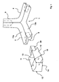
- the in the FIGS. 1 and 2 illustrated node 1 has three neck elements 2, 3 and 4, which are formed in principle the same and running one another the node 1 two.
- the rods received by the node 1 are designated 10.
- Such a rod 10 has two mutually parallel grooves 11 and 12, wherein the grooves 11 and 12 are connected by a Kehlline 13 with each other.
- the height h 1 of the Kehl line with respect to the flank 14 is about 2/3 of the height of the flank 15.
- the grooves 11 and 12 are substantially the same. This means that the width x 1 of the groove 11 is equal to the width x 2 of the groove 12.
- FIG. 1 results, such a rod has a shoe 20, the shape of which is made corresponding to the notch 8 in the neck element 2 to 4 of the node 1, that is formed in cross section in the manner of an unequal leg trapezoid.
- the formation of the node is held in relation to the grooves 11 and 12 as well as that of the rod 10. It is essential that the grooves 11 a and 12 a in the node 1, starting from the neck elements 2, 3 and 4, run into each other, as this is very descriptive FIG. 1 but also out FIG. 2 results.
- Increasing the stability of a bar structure formed in this way compared to a bar structure having additional elements and bars of rectangular and square cross-section is that the bulges due to the grooves create an increase in stability similar to a bridge vault or building vault. This applies in particular to the shape of the knot, which is formed by the area enclosed by the attachment elements in the manner of a vault, resulting in increased stability compared to a pure rectangular shape.
- the cuboid bar structure according to Fig. 3 includes a plurality of nodes 1, which communicate with each other by bars 10.
- spring / damper systems 100 are arranged, which absorb the hollow body designated 120 elastically movably in all three spatial directions damping. From such cuboidal rod structures according to Fig. 3 an entire building can be created in which a plurality of such cuboidal bar structures are arranged side by side and / or one above the other and are connected to each other, if the individual cuboidal bar structures accommodate hollow body 120, which are formed as living spaces.
- the damper of the spring / damper system 100 of a bar structure have a mutually different damping characteristic, there is no risk that in shock, for example, as a result of earthquakes, the elastically yielding in the cuboidal rod structure hollow body lifted up due to any resonances. Rather, it is conceivable that with a suitable choice of the attenuation characteristic of the individual systems of each cuboid bar structure, the vibrations occurring in the building made therefrom at least partially compensate, since they partially cancel each other out. It should be noted that the mass and the spring characteristic determine the resonant frequency and the damper of such a system, the oscillation path in a frequency range.
Landscapes
- Engineering & Computer Science (AREA)
- Physics & Mathematics (AREA)
- Architecture (AREA)
- Acoustics & Sound (AREA)
- Electromagnetism (AREA)
- Civil Engineering (AREA)
- Structural Engineering (AREA)
- General Engineering & Computer Science (AREA)
- Textile Engineering (AREA)
- Mechanical Engineering (AREA)
- Buildings Adapted To Withstand Abnormal External Influences (AREA)
- Reinforcement Elements For Buildings (AREA)
- Mutual Connection Of Rods And Tubes (AREA)
- Joining Of Corner Units Of Frames Or Wings (AREA)
- Mirrors, Picture Frames, Photograph Stands, And Related Fastening Devices (AREA)
- Installation Of Bus-Bars (AREA)
- Building Environments (AREA)
Description
- Die vorliegende Erfindung betrifft ein quaderförmiges Stabtragwerk zur Bildung eines Rahmens, umfassend mehrere Knoten und die Knoten verbindende Stäbe.
- Aus der
DE 33 35 004 A1 ist ein Möbelelement mit Eckverbindungselement und Kantenstäben, die die Eckverbindungselemente zur Bildung eines räumlichen Gebildes verbinden, bekannt. Die Kantenstäbe nehmen hierbei Seitenplatten auf, um ein geschlossenes Möbelsystem, z. B. einen Schrank, zu schaffen. - Dokument
DE 3335004 A1 beschreibt ein quaderförmiges Stabtragewerk mit den Merkmalen das Oberbegriffs des Anspruchs 1. - Stabtragwerke sind weiterhin auf dem Gebiet der Fachwerktechnik bekannt. Fachwerke werden üblicherweise aus Holz oder Metall hergestellt. Bekannt sind allerdings auch Tragwerke in der oben beschriebenen Form aus Beton, wobei im Bereich des Knotens die einzelnen Betonträger zusammenlaufen und zur Erhöhung der Festigkeit mit Armierungen versehen sind.
- Die Querschnitte derartiger Stabtragwerke sind meistens rechteckig oder quadratisch, im Falle einer Metallkonstruktion eines Fachwerkes sind die Querschnitte der Träger insbesondere als Winkelstreben ausgebildet.
- Im Zuge von Berechnungen hat sich nun allerdings herausgestellt, dass eine Erhöhung der Festigkeit eines Stabtragwerkes zur Bildung eines Rahmens, sei dieser zwei- oder dreidimensional, dadurch erreicht werden kann, dass ein solches quaderförmiges Stabtragwerk mit Knoten versehen ist, wobei jeder Stab mindestens eine in Längsrichtung des Stabes sich erstreckende Auskehlung aufweist, wobei sich die jeweilige Auskehlung bis in den Knoten fortsetzt. Unter einer Auskehlung wird eine sich in Längsrichtung erstreckende bogenförmige Ausnehmung verstanden. Wie bereits ausgeführt, konnte durch eine solche Auskehlung erreicht werden, dass die Tragfähigkeit eines Stabtragwerkes der eingangs genannten Art wesentlich erhöht wurde. Insbesondere konnte eine Erhöhung dann festgestellt werden, wenn zwei derartige Auskehlungen jeweils parallel zueinander verlaufend das Stabtragwerk, d. h. auch den einzelnen Stab, bestimmen. Der Vorteil liegt nicht nur in einer gegenüber einem Vollstab mit beispielsweise rechteckigem oder quadratischem Querschnitt erhöhten Stabilität, sondern auch an einer schlankeren und grazileren Bauweise.
- Enge solche Möglichkeit eröffnet sich insbesondere dann, wenn dieses Stabtragwerk aus Beton, insbesondere einem hochfesten Beton, hergestellt wird, wie er In der
DE 103 32 491 A1 beschrieben ist. Grundsätzlich spricht allerdings nichts dagegen, ein solches Stabtragwerk auch aus anderen Materialien, insbesondere aus Stahl oder Kunststoff, in der vorbeschriebenen Form herzustellen. Es hat sich in diesem Zusammenhang insbesondere herausgestellt, dass mit einem solchen aus hochfestem Beton hergestellten Stabtragwerk z. B. auch der Innere Rahmen einer Waschmaschine herstellbar ist. Der Vorteil in der Verwendung von Beton gegenüber Stahl besteht in der heutigen Zeit insbesondere darin, dass Stahl gegenüber Beton wesentlich teurer ist. - Nach einem besonderen Merkmal der Erfindung weist der Knoten mindestens zwei Ansatzelemente zur Aufnahme jeweils eines Stabes auf. Hierdurch ist ein Stabtragwerk quasi nach dem Baukastenprinzip aus vorgefertigten Teilen in nahezu beliebiger Größe herstellbar. Durch die Anordnung eines Ansatzelementes und einer korrespondierenden Ausbildung des Stabendes wird eine in zwei Raumrichtungen formschlüssige Verbindung erreicht, was zum einen der Erhöhung der Passgenauigkeit und zum anderen der Erhöhung der Stabilität dient.
- Nach einem weiteren vorteilhaften Merkmal der Erfindung ist vorgesehen, dass das Ansatzelement des Knotens eine Ausklinkung aufweist, wobei der Stab endseitig einen entsprechend der Form der Ausklinkung ausgebildeten Schuh aufweist, wobei der Stab mit dem Ansatzelement im Bereich der Ausklinkung insbesondere stoffschlüssig, z. B. durch Kleben mittels Epoxidharz, verbindbar ist. Die Ausklinkung ist hierbei im Querschnitt nach Art eines ungleichschenkligen Trapezes ausgebildet, wobei die Ausklinkung entsprechend dem Verlauf der parallel zueinander verlaufenden beiden Kehlen, die im Wesentlichen in ihrer flächenmäßigen Erstreckung gleich groß sind, abfallend ausgebildet ist.
- Kennzeichnend für die Erfindung ist nun, dass ein solches quaderförmiges Stabtragwerk einen Hohlkörper in alle drei Raumrichtungen elastisch nachgiebig aufnimmt. Dies vor folgendem Hintergrund: Das Stabtragwerk in Form eines Quaders kann als Bauelement eine Dimension haben, in der es in der Lage ist, Hohlkörper in Form von Gebäuderäumen aufzunehmen. Derartige quaderförmige Stabtragwerke können zu mehreren zur Erstellung eines Gebäudes hintereinander und aufeinander gesetzt werden, wobei jeder dieser Quader einen solchen Hohlkörper in Form eines Gebäuderaumes in alle drei Raumrichtungen durch ein Feder-/Dämpfersystem elastisch nachgiebig aufnimmt. Der Vorteil dieser Ausgestaltung besteht darin, dass mit einem solchen Bauwerk eine erdbebensichere Bauweise verwirklicht werden kann. Dies deshalb, weil die durch die Erschütterungen in Schwingung gesetzten starren Gebäudeteile eine verhältnismäßig geringe Masse haben und die elastisch aufgehängten Hohlkörper die Schwingungen der starren Gebäudeteile partiell kompensieren. Dies gilt dann, wenn die Erregerfrequenz und Dämpfung von Rahmen und Hohlkörper aufeinander abgestimmt werden. Hieraus wird deutlich, dass dann, wenn eine Mehrzahl solcher ein Gebäude bildende Quader durch beispielsweise Erschütterungen zur Schwingung angeregt wird, die unterschiedlichen Dämpfungseigenschaften des Feder- und Dämpfersystems das Aufschwingen eines solchermaßen hergestellten Gebäudes im Wesentlichen vermeiden.
- Im Einzelnen ist vorgesehen, dass ein Feder-/Dämpfersystem im Zentrum jedes Knotens angeordnet ist. Dies deshalb, weil dort das Stabtragwerk die höchste Stabilität aufweist. Zur Aufnahme des Feder-/Dämpfersystems ist des Weiteren vorgesehen, dass das Stabtragwerk Aufnahmeelemente, beispielsweise in Form von Ösen, aufweist. Insbesondere ist vorgesehen, dass die Aufnahmeelemente im Bereich der mittleren Kehllinie angeordnet sind. Denkbar ist ebenfalls die Anordnung von Buchsen zum Einlegen oder Einschrauben des Feder-/Dämpfersystems.
- Anhand der Zeichnungen wird die Erfindung nachstehend beispielhaft näher erläutert.
- Figur 1
- zeigt den Knoten eines Stabtragwerkes mit drei Ansatzelementen zur Verbindung mit jeweils einem Stab;
- Figur 2
- zeigt eine weitere Ansicht auf den Knoten gemäß
Figur 1 ; - Figur 3
- zeigt ein quaderförmiges Stabtragwerk mit elastisch aufgehängtem Hohlkörper als Teil eines Gebäudes.
- Der in den
Figuren 1 und2 dargestellte Knoten 1 besitzt drei Ansatzelemente 2, 3 und 4, die vom Grundsatz her gleich ausgebildet sind und ineinanderlaufend den Knotens 1 beiden. Die durch den Knoten 1 aufgenommenen Stäbe sind mit 10 bezeichnet. Ein solcher Stab 10 weist zwei parallel zueinander verlaufende Auskehlungen 11 und 12 auf, wobei die Auskehlungen 11 und 12 durch eine Kehllinie 13 miteinander in Verbindung stehen. Die Höhe h1 der Kehllinie bezogen auf die Flanke 14 beträgt etwa 2/3 der Höhe der Flanke 15. Im Übrigen gilt, dass die Auskehlungen 11 und 12 im Wesentlichen gleich sind. Das bedeutet, dass die Breite x1 der Auskehlung 11 gleich der Breite x2 der Auskehlung 12 ist. - Wie sich ebenfalls aus
Figur 1 ergibt, besitzt ein solcher Stab einen Schuh 20, dessen Form korrespondierend zu der Ausklinkung 8 in dem Ansatzelement 2 bis 4 des Knotens 1 getroffen ist, d. h. im Querschnitt nach Art eines ungleichschenkligen Trapezes ausgebildet ist. Die Ausbildung des Knotens ist in Bezug auf die Auskehlungen 11 und 12 genauso gehalten wie die des Stabes 10. Wesentlich ist, dass die Auskehlungen 11 a und 12a in den Knoten 1, ausgehend von den Ansatzelementen 2, 3 und 4, ineinander laufen, wie sich dies sehr anschaulich ausFigur 1 , aber auch ausFigur 2 ergibt. - Die Erhöhung der Stabilität eines in dieser Weise ausgebildeten Stabtragwerkes gegenüber einem Stabtragwerk, das Zusatzelemente und Stäbe mit rechteckigem und quadratischem Querschnitt aufweist, besteht darin, dass durch die Wölbungen auf Grund der Auskehlungen eine Erhöhung der Stabilität ähnlich einem Brückengewölbe oder einem Gebäudegewölbe erzeugt wird. Dies gilt insbesondere für die Gestalt des Knotens, der durch den von den Ansatzelementen eingeschlossenen Bereich nach Art eines Gewölbes ausgebildet ist, wodurch sich die gegenüber einer reinen Rechteckform erhöhte Stabilität ergibt.
- Das quaderförmige Stabtragwerk gemäß
Fig. 3 umfasst mehrere Knoten 1, die durch Stäbe 10 miteinander in Verbindung stehen. Im Bereich der Knoten 1 sind Feder/-Dämpfersysteme 100 angeordnet, die den mit 120 bezeichneten Hohlkörper in alle drei Raumrichtungen elastisch beweglich dämpfend aufnehmen. Aus solchen quaderförmigen Stabtragwerken gemäßFig. 3 kann ein gesamtes Gebäude erstellt werden, in dem nämlich mehrere derartiger quaderförmigen Stabtragwerke nebeneinander und/oder übereinander angeordnet werden und miteinander verbunden sind, wenn die einzelnen quaderförmigen Stabtragwerke Hohlkörper 120 aufnehmen, die als Wohnräume ausgebildet sind. Insbesondere wenn die Dämpfer des Feder-/Dämpfersystems 100 eines Stabtragwerkes eine zueinander unterschiedliche Dämpfungskennlinie aufweisen, besteht nicht die Gefahr, dass bei Erschütterungen, beispielsweise als Folge eines Erdbebens, sich die im quaderförmigen Stabtragwerk elastisch nachgiebig gelagerten Hohlkörper aufgrund etwaiger Resonanzen aufschwingen. Vielmehr ist denkbar, dass bei geeigneter Wahl der Dämpfungskennlinie der einzelnen Systeme eines jeden quaderförmigen Stabtragwerkes sich die auftretenden Schwingungen in dem hieraus hergestellten Gebäude zumindest partiell kompensieren, da sie sich teilweise gegenseitig auslöschen. Hierbei ist zu berücksichtigen, dass die Masse und die Federkennlinie die Resonanzfrequenz bestimmen und der Dämpfer eines solchen Systems den Schwingungsweg in einem Frequenzbereich.
Claims (14)
- Quaderförmiges Stabtragwerk zur Bildung eines Rahmens, umfassend mehrere Knoten (1) und die Knoten (1) verbindende Stäbe (10), wobei jeder Stab (10) mindestens eine in Längsrichtung des Stabes (10) sich erstreckende Auskehlung (11, 12) aufweist, wobei sich die jeweilige Auskehlung (11, 12) bis in den Knoten (1) fortsetzt, dadurch gekennzeichnet, dass das quaderförmige Stabtragwerk einen Hohlkörper (120) in alle drei Raumrichtungen elastisch nachgiebig aufnimmt.
- Stabtragwerk nach Anspruch 1,
dadurch gekennzeichnet,
dass der Knoten (1) mindestens zwei Ansatzelemente (2, 3, 4) zur Aufnahme jeweils eines Stabes (10) aufweist. - Stabtragwerk nach Anspruch 1,
dadurch gekennzeichnet,
dass der Stab (10) zwei parallel zueinander verlaufende Auskehlungen (11, 12) aufweist, wobei zwischen den beiden Auskehlungen (11, 12) eine mittlere Kehllinie verläuft. - Stabtragwerk nach Anspruch 1,
dadurch gekennzeichnet,
dass sich durch die Auskehlung (11, 12) eine Kehllinie (13) ergibt, die eine geringere Höhe (h1) als die Seitenflanke (15) des Stabes (10) aufweist. - Stabtragwerk nach Anspruch 4,
dadurch gekennzeichnet,
dass die Höhe (h1) der Kehllinie (13) etwa 2/3 der Höhe der Seitenflanke (15) des Stabes (10) beträgt. - Stabtragwerk nach Anspruch 2,
dadurch gekennzeichnet,
dass das Ansatzelement (2, 3, 4) des Knotens (1) eine Ausklinkung (8) aufweist, wobei der Stab (10) endseitig einen entsprechend der Form der Ausklinkung (8) ausgebildeten Schuh (20) aufweist, wobei der Schuh (20) mit dem Ansatzelement (2, 3, 4) im Bereich der Ausklinkung (8) insbesondere stoffschlüssig, z. B. durch Kleben, verbindbar ist. - Stabtragwerk nach Anspruch 6,
dadurch gekennzeichnet,
dass die Ausklinkung (8) im Querschnitt nach Art eines ungleichschenkligen Trapezes ausgebildet ist. - Stabtragwerk nach Anspruch 1,
dadurch gekennzeichnet,
dass die Auskehlungen (11, 12) gleich groß sind. - Stabtragwerk nach Anspruch 1,
dadurch gekennzeichnet,
dass das quaderförmige Stabtragwerk mehrere Feder-/Dämpfersysteme (100) aufweist, an denen der Hohlkörper (120) aufgehängt ist. - Stabtragwerk nach Anspruch 9,
dadurch gekennzeichnet,
dass die Feder-/Dämpfersysteme (100) im Zentrum eines Knotens (1) angeordnet sind. - Stabtragwerk nach Anspruch 9,
dadurch gekennzeichnet,
dass zur Aufnahme der Feder-/Dämpfersysteme (100) das Stabtragwerk Aufnahmeelemente aufweist. - Stabtragwerk nach Anspruch 11,
dadurch gekennzeichnet,
dass die Aufnahmeelemente im Bereich der mittleren Kehllinie (13) angeordnet sind. - Stabtragwerk nach Anspruch 9,
dadurch gekennzeichnet,
dass die Feder-/Dämpfersysteme (100) in ihrer Dämpfungskennlinie einstellbar sind. - Stabtragwerk nach Anspruch 1,
dadurch gekennzeichnet,
dass sowohl die Stäbe (10) als auch die Knoten (1) aus Beton ausgebildet sind.
Applications Claiming Priority (2)
| Application Number | Priority Date | Filing Date | Title |
|---|---|---|---|
| DE102006036988.2A DE102006036988B4 (de) | 2006-08-08 | 2006-08-08 | Stabtragwerk zur Bildung eines Rahmens, umfassend mehrere Knoten und die Knoten verbindende Stäbe |
| EP07801179A EP2049742A2 (de) | 2006-08-08 | 2007-07-28 | Stabtragwerk zur bildung eines rahmens, umfassend mehrere knoten und die knoten verbindende stäbe |
Related Parent Applications (2)
| Application Number | Title | Priority Date | Filing Date |
|---|---|---|---|
| EP07801179.8 Division | 2007-07-28 | ||
| EP07801179A Division EP2049742A2 (de) | 2006-08-08 | 2007-07-28 | Stabtragwerk zur bildung eines rahmens, umfassend mehrere knoten und die knoten verbindende stäbe |
Publications (2)
| Publication Number | Publication Date |
|---|---|
| EP2093338A1 EP2093338A1 (de) | 2009-08-26 |
| EP2093338B1 true EP2093338B1 (de) | 2010-10-27 |
Family
ID=38954670
Family Applications (3)
| Application Number | Title | Priority Date | Filing Date |
|---|---|---|---|
| EP09006105A Not-in-force EP2093338B1 (de) | 2006-08-08 | 2007-07-28 | Stabtragwerk zur Bildung eines Rahmens, umfassend mehrere Knoten und die Knoten verbindende Stäbe |
| EP20100012239 Not-in-force EP2292857B1 (de) | 2006-08-08 | 2007-07-28 | Gebäudewand umfassend mehrere Stabtragwerke umfassend mehrere Knoten und die Knoten verbindende Stäbe |
| EP07801179A Withdrawn EP2049742A2 (de) | 2006-08-08 | 2007-07-28 | Stabtragwerk zur bildung eines rahmens, umfassend mehrere knoten und die knoten verbindende stäbe |
Family Applications After (2)
| Application Number | Title | Priority Date | Filing Date |
|---|---|---|---|
| EP20100012239 Not-in-force EP2292857B1 (de) | 2006-08-08 | 2007-07-28 | Gebäudewand umfassend mehrere Stabtragwerke umfassend mehrere Knoten und die Knoten verbindende Stäbe |
| EP07801179A Withdrawn EP2049742A2 (de) | 2006-08-08 | 2007-07-28 | Stabtragwerk zur bildung eines rahmens, umfassend mehrere knoten und die knoten verbindende stäbe |
Country Status (5)
| Country | Link |
|---|---|
| US (1) | US20100186317A1 (de) |
| EP (3) | EP2093338B1 (de) |
| AT (1) | ATE486178T1 (de) |
| DE (2) | DE102006036988B4 (de) |
| WO (1) | WO2008017288A2 (de) |
Families Citing this family (8)
| Publication number | Priority date | Publication date | Assignee | Title |
|---|---|---|---|---|
| DE102011101454A1 (de) * | 2011-05-12 | 2012-11-15 | De-Sta-Co Europe Gmbh | Tragrahmen |
| CN102359189B (zh) * | 2011-07-27 | 2013-06-26 | 华北水利水电学院 | 超薄壁钢结构屋架平梁、屋顶连接件及其连接结构 |
| US8739477B2 (en) * | 2011-11-14 | 2014-06-03 | Corefirst, Llc | Modular safety system |
| AU2013235162B2 (en) * | 2012-03-20 | 2017-09-21 | J Martin Lovely Thompson | Framework serving as structural support and utility space |
| US9745741B2 (en) * | 2013-03-14 | 2017-08-29 | Timothy A. Hayes | Structural connection mechanisms for providing discontinuous elastic behavior in structural framing systems |
| JP6377546B2 (ja) * | 2014-12-26 | 2018-08-22 | 宮澤 健二 | 制震壁面構造、制震デバイスの連結方法 |
| US10100453B2 (en) | 2016-02-18 | 2018-10-16 | Whirlpool Corporation | Laundry treating appliance with tuned suspension system |
| CN111395763A (zh) * | 2020-04-03 | 2020-07-10 | 陕西建工机械施工集团有限公司 | 局部曲面毂型节点单层网壳块体拼装施工工艺 |
Family Cites Families (35)
| Publication number | Priority date | Publication date | Assignee | Title |
|---|---|---|---|---|
| US1362069A (en) * | 1919-05-06 | 1920-12-14 | Joseph R Witzel | Building construction |
| US3110464A (en) * | 1959-10-29 | 1963-11-12 | Korfund Dynamics Corp | Shock isolators |
| DE1461000A1 (de) * | 1962-07-09 | 1969-02-13 | Licentia Gmbh | Waschmaschine |
| US3743332A (en) * | 1971-05-17 | 1973-07-03 | H Sonolet | Assembling of tubular elements |
| US3711133A (en) * | 1971-06-02 | 1973-01-16 | O Werner | Expandable and contractible tubing support structure |
| US3858989A (en) * | 1973-09-10 | 1975-01-07 | Frank P Field | Joint for connecting members |
| DE2515569B2 (de) * | 1975-04-10 | 1978-02-16 | Veyhl-Produktion KG, 7261 Zwerenberg | Verbindung fuer drei rohrabschnitte |
| DE2519769C3 (de) * | 1975-05-02 | 1982-07-08 | Estel Hoesch Werke Ag, 4600 Dortmund | Verbindungsstück für die Knotenausbildung von wellenbeaufschlagten Fachwerkkonstruktionen aus Großrohren, insbesondere für Bohrinseln |
| JPS51136070A (en) * | 1975-05-19 | 1976-11-25 | Takashi Kawatsu | Pipe connector |
| DE2619769C2 (de) * | 1976-05-05 | 1986-02-13 | Robert Bosch Gmbh, 7000 Stuttgart | Druckbegrenzer |
| DE3164160D1 (en) * | 1980-08-07 | 1984-07-19 | Colin John Stewart Stephenson | A framework structure |
| GB2140670B (en) * | 1983-06-03 | 1987-04-08 | Hsiao Yu Sheng | Safety steel angle assembly rack |
| DE3335004A1 (de) * | 1983-09-28 | 1985-04-11 | Guan-Zhong 7000 Stuttgart Liu | Moebel-element |
| NL8400519A (nl) * | 1984-02-17 | 1985-09-16 | Keen Egbert | Inrichting met uit buisstukken en koppelstukken samengesteld gestel en koppelstuk daarvoor. |
| US4712695A (en) * | 1986-07-25 | 1987-12-15 | Cheng Huey Der | Structural frame connector |
| DE8701515U1 (de) * | 1987-01-31 | 1987-03-26 | Schneider, Siegfried, 5650 Solingen | Bauelement für Baukastensystem |
| CH678970A5 (en) * | 1987-04-28 | 1991-11-29 | Hans Diehl | Bar type support system |
| US5003741A (en) * | 1988-06-20 | 1991-04-02 | Yeh Kuo Huei | Structure of multi-function frame members |
| US5066161A (en) * | 1989-05-08 | 1991-11-19 | Pinney Richard C | Framework for cabinet structure |
| KR100260626B1 (ko) * | 1991-01-09 | 2000-07-01 | 미사와 치요지 | 건물 유닛에 있어서의 접합부재 및 그 제조방법 |
| US5462141A (en) * | 1993-05-07 | 1995-10-31 | Tayco Developments, Inc. | Seismic isolator and method for strengthening structures against damage from seismic forces |
| US5435110A (en) * | 1993-08-04 | 1995-07-25 | Aluminum Company Of America | Method of joining of hollow framework and associated frame assembly |
| US5644871A (en) * | 1995-07-18 | 1997-07-08 | Eli Gonen | Modular building system |
| EP1036638A4 (de) * | 1997-07-17 | 2000-12-20 | Rita Engineering Consultants C | Zementblock, verbindungsmöglichkeit des zementblocks und struktur aus zementblöcken |
| DE19744001C2 (de) * | 1997-09-26 | 2003-04-17 | Ulrich Huber | Bauwerk als dynamisches Schwingungssystem mit drei freien Bewegungsachsen |
| JP3319726B2 (ja) * | 1998-12-10 | 2002-09-03 | 道夫 倉持 | 免震装置 |
| US6530182B2 (en) * | 2000-10-23 | 2003-03-11 | Kazak Composites, Incorporated | Low cost, light weight, energy-absorbing earthquake brace |
| DE10130216C1 (de) * | 2001-06-22 | 2003-01-30 | Simon Bauer | Knoten für ein modulares Bausystem |
| DE10215442B4 (de) * | 2002-04-09 | 2004-02-19 | Thyssenkrupp Stahl Ag | Dreidimensionale Knotenstruktur |
| EP1408176A1 (de) * | 2002-10-08 | 2004-04-14 | Kosche Profilummantelung GmbH | Verbindungsvorrichtung für Profilleisten |
| US6854238B2 (en) * | 2002-11-12 | 2005-02-15 | Alfred Boots | Structural connection system for frameworks |
| DE10332491B4 (de) * | 2003-07-16 | 2006-01-12 | Universität Kassel | Betonmischung für einen ultrahochfesten Beton sowie deren Verwendung |
| ITBO20030764A1 (it) * | 2003-12-19 | 2005-06-20 | Ferrari Spa | Telaio metallico composto dall'unione di una pluralita' di elementi estrusi e metodo per la sua realizzazione |
| US7044825B2 (en) * | 2004-07-27 | 2006-05-16 | Connector Set Limited Partnership | Panel and girder system for construction toy |
| US7827738B2 (en) * | 2006-08-26 | 2010-11-09 | Alexander Abrams | System for modular building construction |
-
2006
- 2006-08-08 DE DE102006036988.2A patent/DE102006036988B4/de not_active Expired - Fee Related
-
2007
- 2007-07-28 EP EP09006105A patent/EP2093338B1/de not_active Not-in-force
- 2007-07-28 DE DE502007005493T patent/DE502007005493D1/de active Active
- 2007-07-28 EP EP20100012239 patent/EP2292857B1/de not_active Not-in-force
- 2007-07-28 EP EP07801179A patent/EP2049742A2/de not_active Withdrawn
- 2007-07-28 US US12/376,767 patent/US20100186317A1/en not_active Abandoned
- 2007-07-28 WO PCT/DE2007/001338 patent/WO2008017288A2/de not_active Ceased
- 2007-07-28 AT AT09006105T patent/ATE486178T1/de active
Also Published As
| Publication number | Publication date |
|---|---|
| DE102006036988A1 (de) | 2008-02-21 |
| ATE486178T1 (de) | 2010-11-15 |
| EP2292857B1 (de) | 2015-04-29 |
| WO2008017288A2 (de) | 2008-02-14 |
| EP2049742A2 (de) | 2009-04-22 |
| WO2008017288A3 (de) | 2008-05-29 |
| EP2292857A1 (de) | 2011-03-09 |
| US20100186317A1 (en) | 2010-07-29 |
| DE102006036988B4 (de) | 2015-10-01 |
| EP2093338A1 (de) | 2009-08-26 |
| DE502007005493D1 (de) | 2010-12-09 |
Similar Documents
| Publication | Publication Date | Title |
|---|---|---|
| EP2093338B1 (de) | Stabtragwerk zur Bildung eines Rahmens, umfassend mehrere Knoten und die Knoten verbindende Stäbe | |
| DE2835849A1 (de) | Waerme- und schallisolierende verlorene schalung | |
| EP2989263B1 (de) | Geschossdeckenkonstruktion und gebäude aus holz | |
| EP2060694A1 (de) | Gebäudewandelement | |
| DE69911055T2 (de) | Triangulierte holzbauweisen, wie gitterträger, brücke, decken | |
| EP1597442B1 (de) | Zweischalige trennwand mit einer f llung aus mineralwolle | |
| EP2337903B1 (de) | Anschlusselemente für gebäudeverbindungen | |
| DE102010016877A1 (de) | Mauerziegel mit Dämmfüllung | |
| AT508576B1 (de) | Steinkorb- bzw. gabionenanordnung | |
| DE102013002104A1 (de) | Tragkonstruktion aus Holz mit einem ersten stab- oder flächenförmigen Tragelement und mindestens einem zweiten stab- oder flächenförmigen Tragelement | |
| CN104364451A (zh) | 建筑用组装式墙体框架及利用此的天花板框架 | |
| EP2196592B1 (de) | Holzdeckenelement oder Holzwandelement aus von aneinander zusammengefügten Holzbrettern | |
| DE69530287T2 (de) | Konstruktionsrahmen | |
| EP0564903A2 (de) | Bauelement zur Herstellung insbesondere von Baukörperkonturen | |
| WO2017089605A1 (de) | Modulare plattform | |
| EP1995387B1 (de) | Holzbauelement und daraus gebildetes Wandelement | |
| EP0796958B1 (de) | Mehrzweckplatte | |
| DE102008002899A1 (de) | Bauelement mit Edelstahlträger | |
| EP4508285A1 (de) | Bauteil zur herstellung von gebäudeteilen wie wände und decken | |
| EP1878845A2 (de) | Profilträger | |
| AT520790B1 (de) | Bauelement | |
| DE20013321U1 (de) | Schaltafel | |
| DE202012007558U1 (de) | Mauerstein | |
| DE1975894U (de) | Traggeruest-bauteil zum aufbau mehrschaliger bauelemente. | |
| CH162062A (de) | Hohlwand mit durch Binder verbundenen Wandschalen. |
Legal Events
| Date | Code | Title | Description |
|---|---|---|---|
| PUAI | Public reference made under article 153(3) epc to a published international application that has entered the european phase |
Free format text: ORIGINAL CODE: 0009012 |
|
| 17P | Request for examination filed |
Effective date: 20090525 |
|
| AC | Divisional application: reference to earlier application |
Ref document number: 2049742 Country of ref document: EP Kind code of ref document: P |
|
| AK | Designated contracting states |
Kind code of ref document: A1 Designated state(s): AT BE BG CH CY CZ DE DK EE ES FI FR GB GR HU IE IS IT LI LT LU LV MC MT NL PL PT RO SE SI SK TR |
|
| RIN1 | Information on inventor provided before grant (corrected) |
Inventor name: SPORLEDER, BERND Inventor name: MACHNER, PETER Inventor name: WOLFRAM, ANDREAS Inventor name: KLATECKI, MARC Inventor name: KIRSTEN, PETER IGNAZ |
|
| R17P | Request for examination filed (corrected) |
Effective date: 20090824 |
|
| 17Q | First examination report despatched |
Effective date: 20090525 |
|
| GRAP | Despatch of communication of intention to grant a patent |
Free format text: ORIGINAL CODE: EPIDOSNIGR1 |
|
| GRAS | Grant fee paid |
Free format text: ORIGINAL CODE: EPIDOSNIGR3 |
|
| GRAA | (expected) grant |
Free format text: ORIGINAL CODE: 0009210 |
|
| AC | Divisional application: reference to earlier application |
Ref document number: 2049742 Country of ref document: EP Kind code of ref document: P |
|
| AK | Designated contracting states |
Kind code of ref document: B1 Designated state(s): AT BE BG CH CY CZ DE DK EE ES FI FR GB GR HU IE IS IT LI LT LU LV MC MT NL PL PT RO SE SI SK TR |
|
| REG | Reference to a national code |
Ref country code: GB Ref legal event code: FG4D Free format text: NOT ENGLISH |
|
| REG | Reference to a national code |
Ref country code: CH Ref legal event code: EP |
|
| REG | Reference to a national code |
Ref country code: IE Ref legal event code: FG4D Free format text: LANGUAGE OF EP DOCUMENT: GERMAN |
|
| REF | Corresponds to: |
Ref document number: 502007005493 Country of ref document: DE Date of ref document: 20101209 Kind code of ref document: P |
|
| REG | Reference to a national code |
Ref country code: NL Ref legal event code: VDEP Effective date: 20101027 |
|
| LTIE | Lt: invalidation of european patent or patent extension |
Effective date: 20101027 |
|
| PG25 | Lapsed in a contracting state [announced via postgrant information from national office to epo] |
Ref country code: LT Free format text: LAPSE BECAUSE OF FAILURE TO SUBMIT A TRANSLATION OF THE DESCRIPTION OR TO PAY THE FEE WITHIN THE PRESCRIBED TIME-LIMIT Effective date: 20101027 |
|
| REG | Reference to a national code |
Ref country code: IE Ref legal event code: FD4D |
|
| PG25 | Lapsed in a contracting state [announced via postgrant information from national office to epo] |
Ref country code: NL Free format text: LAPSE BECAUSE OF FAILURE TO SUBMIT A TRANSLATION OF THE DESCRIPTION OR TO PAY THE FEE WITHIN THE PRESCRIBED TIME-LIMIT Effective date: 20101027 Ref country code: SI Free format text: LAPSE BECAUSE OF FAILURE TO SUBMIT A TRANSLATION OF THE DESCRIPTION OR TO PAY THE FEE WITHIN THE PRESCRIBED TIME-LIMIT Effective date: 20101027 Ref country code: BG Free format text: LAPSE BECAUSE OF FAILURE TO SUBMIT A TRANSLATION OF THE DESCRIPTION OR TO PAY THE FEE WITHIN THE PRESCRIBED TIME-LIMIT Effective date: 20110127 Ref country code: SE Free format text: LAPSE BECAUSE OF FAILURE TO SUBMIT A TRANSLATION OF THE DESCRIPTION OR TO PAY THE FEE WITHIN THE PRESCRIBED TIME-LIMIT Effective date: 20101027 Ref country code: PT Free format text: LAPSE BECAUSE OF FAILURE TO SUBMIT A TRANSLATION OF THE DESCRIPTION OR TO PAY THE FEE WITHIN THE PRESCRIBED TIME-LIMIT Effective date: 20110228 Ref country code: LV Free format text: LAPSE BECAUSE OF FAILURE TO SUBMIT A TRANSLATION OF THE DESCRIPTION OR TO PAY THE FEE WITHIN THE PRESCRIBED TIME-LIMIT Effective date: 20101027 Ref country code: IS Free format text: LAPSE BECAUSE OF FAILURE TO SUBMIT A TRANSLATION OF THE DESCRIPTION OR TO PAY THE FEE WITHIN THE PRESCRIBED TIME-LIMIT Effective date: 20110227 Ref country code: FI Free format text: LAPSE BECAUSE OF FAILURE TO SUBMIT A TRANSLATION OF THE DESCRIPTION OR TO PAY THE FEE WITHIN THE PRESCRIBED TIME-LIMIT Effective date: 20101027 |
|
| PG25 | Lapsed in a contracting state [announced via postgrant information from national office to epo] |
Ref country code: GR Free format text: LAPSE BECAUSE OF FAILURE TO SUBMIT A TRANSLATION OF THE DESCRIPTION OR TO PAY THE FEE WITHIN THE PRESCRIBED TIME-LIMIT Effective date: 20110128 |
|
| PG25 | Lapsed in a contracting state [announced via postgrant information from national office to epo] |
Ref country code: EE Free format text: LAPSE BECAUSE OF FAILURE TO SUBMIT A TRANSLATION OF THE DESCRIPTION OR TO PAY THE FEE WITHIN THE PRESCRIBED TIME-LIMIT Effective date: 20101027 Ref country code: CZ Free format text: LAPSE BECAUSE OF FAILURE TO SUBMIT A TRANSLATION OF THE DESCRIPTION OR TO PAY THE FEE WITHIN THE PRESCRIBED TIME-LIMIT Effective date: 20101027 Ref country code: IE Free format text: LAPSE BECAUSE OF FAILURE TO SUBMIT A TRANSLATION OF THE DESCRIPTION OR TO PAY THE FEE WITHIN THE PRESCRIBED TIME-LIMIT Effective date: 20101027 Ref country code: ES Free format text: LAPSE BECAUSE OF FAILURE TO SUBMIT A TRANSLATION OF THE DESCRIPTION OR TO PAY THE FEE WITHIN THE PRESCRIBED TIME-LIMIT Effective date: 20110207 |
|
| PG25 | Lapsed in a contracting state [announced via postgrant information from national office to epo] |
Ref country code: DK Free format text: LAPSE BECAUSE OF FAILURE TO SUBMIT A TRANSLATION OF THE DESCRIPTION OR TO PAY THE FEE WITHIN THE PRESCRIBED TIME-LIMIT Effective date: 20101027 Ref country code: PL Free format text: LAPSE BECAUSE OF FAILURE TO SUBMIT A TRANSLATION OF THE DESCRIPTION OR TO PAY THE FEE WITHIN THE PRESCRIBED TIME-LIMIT Effective date: 20101027 Ref country code: SK Free format text: LAPSE BECAUSE OF FAILURE TO SUBMIT A TRANSLATION OF THE DESCRIPTION OR TO PAY THE FEE WITHIN THE PRESCRIBED TIME-LIMIT Effective date: 20101027 Ref country code: RO Free format text: LAPSE BECAUSE OF FAILURE TO SUBMIT A TRANSLATION OF THE DESCRIPTION OR TO PAY THE FEE WITHIN THE PRESCRIBED TIME-LIMIT Effective date: 20101027 |
|
| PLBE | No opposition filed within time limit |
Free format text: ORIGINAL CODE: 0009261 |
|
| STAA | Information on the status of an ep patent application or granted ep patent |
Free format text: STATUS: NO OPPOSITION FILED WITHIN TIME LIMIT |
|
| 26N | No opposition filed |
Effective date: 20110728 |
|
| REG | Reference to a national code |
Ref country code: DE Ref legal event code: R097 Ref document number: 502007005493 Country of ref document: DE Effective date: 20110728 |
|
| PG25 | Lapsed in a contracting state [announced via postgrant information from national office to epo] |
Ref country code: MT Free format text: LAPSE BECAUSE OF FAILURE TO SUBMIT A TRANSLATION OF THE DESCRIPTION OR TO PAY THE FEE WITHIN THE PRESCRIBED TIME-LIMIT Effective date: 20101027 Ref country code: IT Free format text: LAPSE BECAUSE OF FAILURE TO SUBMIT A TRANSLATION OF THE DESCRIPTION OR TO PAY THE FEE WITHIN THE PRESCRIBED TIME-LIMIT Effective date: 20101027 |
|
| BERE | Be: lapsed |
Owner name: UNIVERSITAT KASSEL Effective date: 20110731 |
|
| PG25 | Lapsed in a contracting state [announced via postgrant information from national office to epo] |
Ref country code: MC Free format text: LAPSE BECAUSE OF NON-PAYMENT OF DUE FEES Effective date: 20110731 |
|
| GBPC | Gb: european patent ceased through non-payment of renewal fee |
Effective date: 20110728 |
|
| REG | Reference to a national code |
Ref country code: FR Ref legal event code: ST Effective date: 20120330 |
|
| PG25 | Lapsed in a contracting state [announced via postgrant information from national office to epo] |
Ref country code: BE Free format text: LAPSE BECAUSE OF NON-PAYMENT OF DUE FEES Effective date: 20110731 Ref country code: FR Free format text: LAPSE BECAUSE OF NON-PAYMENT OF DUE FEES Effective date: 20110801 |
|
| PG25 | Lapsed in a contracting state [announced via postgrant information from national office to epo] |
Ref country code: GB Free format text: LAPSE BECAUSE OF NON-PAYMENT OF DUE FEES Effective date: 20110728 |
|
| PG25 | Lapsed in a contracting state [announced via postgrant information from national office to epo] |
Ref country code: LU Free format text: LAPSE BECAUSE OF NON-PAYMENT OF DUE FEES Effective date: 20110728 Ref country code: CY Free format text: LAPSE BECAUSE OF EXPIRATION OF PROTECTION Effective date: 20101027 |
|
| REG | Reference to a national code |
Ref country code: AT Ref legal event code: MM01 Ref document number: 486178 Country of ref document: AT Kind code of ref document: T Effective date: 20120731 |
|
| PG25 | Lapsed in a contracting state [announced via postgrant information from national office to epo] |
Ref country code: TR Free format text: LAPSE BECAUSE OF FAILURE TO SUBMIT A TRANSLATION OF THE DESCRIPTION OR TO PAY THE FEE WITHIN THE PRESCRIBED TIME-LIMIT Effective date: 20101027 |
|
| PG25 | Lapsed in a contracting state [announced via postgrant information from national office to epo] |
Ref country code: AT Free format text: LAPSE BECAUSE OF NON-PAYMENT OF DUE FEES Effective date: 20120731 Ref country code: HU Free format text: LAPSE BECAUSE OF FAILURE TO SUBMIT A TRANSLATION OF THE DESCRIPTION OR TO PAY THE FEE WITHIN THE PRESCRIBED TIME-LIMIT Effective date: 20101027 |
|
| PGFP | Annual fee paid to national office [announced via postgrant information from national office to epo] |
Ref country code: CH Payment date: 20170719 Year of fee payment: 11 Ref country code: DE Payment date: 20170523 Year of fee payment: 11 |
|
| REG | Reference to a national code |
Ref country code: DE Ref legal event code: R119 Ref document number: 502007005493 Country of ref document: DE |
|
| REG | Reference to a national code |
Ref country code: CH Ref legal event code: PL |
|
| PG25 | Lapsed in a contracting state [announced via postgrant information from national office to epo] |
Ref country code: DE Free format text: LAPSE BECAUSE OF NON-PAYMENT OF DUE FEES Effective date: 20190201 Ref country code: LI Free format text: LAPSE BECAUSE OF NON-PAYMENT OF DUE FEES Effective date: 20180731 Ref country code: CH Free format text: LAPSE BECAUSE OF NON-PAYMENT OF DUE FEES Effective date: 20180731 |