EP2093366A2 - Fahrzeugklappenpositionssensor - Google Patents
Fahrzeugklappenpositionssensor Download PDFInfo
- Publication number
- EP2093366A2 EP2093366A2 EP09151682A EP09151682A EP2093366A2 EP 2093366 A2 EP2093366 A2 EP 2093366A2 EP 09151682 A EP09151682 A EP 09151682A EP 09151682 A EP09151682 A EP 09151682A EP 2093366 A2 EP2093366 A2 EP 2093366A2
- Authority
- EP
- European Patent Office
- Prior art keywords
- strut
- vehicle
- sensor
- position sensor
- ball stud
- Prior art date
- Legal status (The legal status is an assumption and is not a legal conclusion. Google has not performed a legal analysis and makes no representation as to the accuracy of the status listed.)
- Withdrawn
Links
- 230000005355 Hall effect Effects 0.000 claims description 3
- 238000006073 displacement reaction Methods 0.000 claims 2
- 230000003993 interaction Effects 0.000 claims 2
- 238000000034 method Methods 0.000 claims 1
- 230000007246 mechanism Effects 0.000 abstract description 5
- 238000012545 processing Methods 0.000 abstract description 2
- RUEIBQJFGMERJD-UHFFFAOYSA-N 1,2,3,4,5-pentachloro-6-(2-chlorophenyl)benzene Chemical compound ClC1=CC=CC=C1C1=C(Cl)C(Cl)=C(Cl)C(Cl)=C1Cl RUEIBQJFGMERJD-UHFFFAOYSA-N 0.000 description 5
- 238000012986 modification Methods 0.000 description 4
- 230000004048 modification Effects 0.000 description 4
- 238000004891 communication Methods 0.000 description 3
- 239000004020 conductor Substances 0.000 description 3
- 238000013461 design Methods 0.000 description 3
- 230000000670 limiting effect Effects 0.000 description 3
- 230000036961 partial effect Effects 0.000 description 2
- 229910000831 Steel Inorganic materials 0.000 description 1
- 238000013459 approach Methods 0.000 description 1
- 239000000470 constituent Substances 0.000 description 1
- 230000000694 effects Effects 0.000 description 1
- 230000005684 electric field Effects 0.000 description 1
- 239000011532 electronic conductor Substances 0.000 description 1
- 238000002347 injection Methods 0.000 description 1
- 239000007924 injection Substances 0.000 description 1
- 238000009434 installation Methods 0.000 description 1
- 230000002452 interceptive effect Effects 0.000 description 1
- 230000001788 irregular Effects 0.000 description 1
- 239000000463 material Substances 0.000 description 1
- 230000013011 mating Effects 0.000 description 1
- 239000002991 molded plastic Substances 0.000 description 1
- 230000000717 retained effect Effects 0.000 description 1
- 230000002441 reversible effect Effects 0.000 description 1
- 239000011435 rock Substances 0.000 description 1
- 239000004065 semiconductor Substances 0.000 description 1
- 239000010959 steel Substances 0.000 description 1
- 239000000758 substrate Substances 0.000 description 1
- 238000003466 welding Methods 0.000 description 1
Images




Classifications
-
- E—FIXED CONSTRUCTIONS
- E05—LOCKS; KEYS; WINDOW OR DOOR FITTINGS; SAFES
- E05F—DEVICES FOR MOVING WINGS INTO OPEN OR CLOSED POSITION; CHECKS FOR WINGS; WING FITTINGS NOT OTHERWISE PROVIDED FOR, CONCERNED WITH THE FUNCTIONING OF THE WING
- E05F15/00—Power-operated mechanisms for wings
-
- E—FIXED CONSTRUCTIONS
- E05—LOCKS; KEYS; WINDOW OR DOOR FITTINGS; SAFES
- E05F—DEVICES FOR MOVING WINGS INTO OPEN OR CLOSED POSITION; CHECKS FOR WINGS; WING FITTINGS NOT OTHERWISE PROVIDED FOR, CONCERNED WITH THE FUNCTIONING OF THE WING
- E05F15/00—Power-operated mechanisms for wings
- E05F15/60—Power-operated mechanisms for wings using electrical actuators
- E05F15/603—Power-operated mechanisms for wings using electrical actuators using rotary electromotors
- E05F15/611—Power-operated mechanisms for wings using electrical actuators using rotary electromotors for swinging wings
- E05F15/616—Power-operated mechanisms for wings using electrical actuators using rotary electromotors for swinging wings operated by push-pull mechanisms
- E05F15/622—Power-operated mechanisms for wings using electrical actuators using rotary electromotors for swinging wings operated by push-pull mechanisms using screw-and-nut mechanisms
-
- E—FIXED CONSTRUCTIONS
- E05—LOCKS; KEYS; WINDOW OR DOOR FITTINGS; SAFES
- E05Y—INDEXING SCHEME ASSOCIATED WITH SUBCLASSES E05D AND E05F, RELATING TO CONSTRUCTION ELEMENTS, ELECTRIC CONTROL, POWER SUPPLY, POWER SIGNAL OR TRANSMISSION, USER INTERFACES, MOUNTING OR COUPLING, DETAILS, ACCESSORIES, AUXILIARY OPERATIONS NOT OTHERWISE PROVIDED FOR, APPLICATION THEREOF
- E05Y2201/00—Constructional elements; Accessories therefor
- E05Y2201/60—Suspension or transmission members; Accessories therefor
- E05Y2201/622—Suspension or transmission members elements
- E05Y2201/628—Bearings
- E05Y2201/636—Universal or ball joints
-
- E—FIXED CONSTRUCTIONS
- E05—LOCKS; KEYS; WINDOW OR DOOR FITTINGS; SAFES
- E05Y—INDEXING SCHEME ASSOCIATED WITH SUBCLASSES E05D AND E05F, RELATING TO CONSTRUCTION ELEMENTS, ELECTRIC CONTROL, POWER SUPPLY, POWER SIGNAL OR TRANSMISSION, USER INTERFACES, MOUNTING OR COUPLING, DETAILS, ACCESSORIES, AUXILIARY OPERATIONS NOT OTHERWISE PROVIDED FOR, APPLICATION THEREOF
- E05Y2400/00—Electronic control; Electrical power; Power supply; Power or signal transmission; User interfaces
- E05Y2400/10—Electronic control
- E05Y2400/32—Position control, detection or monitoring
- E05Y2400/322—Position control, detection or monitoring by using absolute position sensors
- E05Y2400/326—Position control, detection or monitoring by using absolute position sensors of the angular type
-
- E—FIXED CONSTRUCTIONS
- E05—LOCKS; KEYS; WINDOW OR DOOR FITTINGS; SAFES
- E05Y—INDEXING SCHEME ASSOCIATED WITH SUBCLASSES E05D AND E05F, RELATING TO CONSTRUCTION ELEMENTS, ELECTRIC CONTROL, POWER SUPPLY, POWER SIGNAL OR TRANSMISSION, USER INTERFACES, MOUNTING OR COUPLING, DETAILS, ACCESSORIES, AUXILIARY OPERATIONS NOT OTHERWISE PROVIDED FOR, APPLICATION THEREOF
- E05Y2800/00—Details, accessories and auxiliary operations not otherwise provided for
- E05Y2800/15—Applicability
- E05Y2800/17—Universally applicable
- E05Y2800/176—Universally applicable on different wing types, weights or sizes
-
- E—FIXED CONSTRUCTIONS
- E05—LOCKS; KEYS; WINDOW OR DOOR FITTINGS; SAFES
- E05Y—INDEXING SCHEME ASSOCIATED WITH SUBCLASSES E05D AND E05F, RELATING TO CONSTRUCTION ELEMENTS, ELECTRIC CONTROL, POWER SUPPLY, POWER SIGNAL OR TRANSMISSION, USER INTERFACES, MOUNTING OR COUPLING, DETAILS, ACCESSORIES, AUXILIARY OPERATIONS NOT OTHERWISE PROVIDED FOR, APPLICATION THEREOF
- E05Y2900/00—Application of doors, windows, wings or fittings thereof
- E05Y2900/50—Application of doors, windows, wings or fittings thereof for vehicles
- E05Y2900/53—Type of wing
- E05Y2900/546—Tailboards, tailgates or sideboards opening upwards
Definitions
- the invention is related to a strut position sensor for application with movable panels such as a rear lift gate of a passenger vehicle.
- a power actuator system is an option used to power open and close movable panels such as the lift gate or hinged/sliding access doors on certain passenger vehicles, vans and light trucks.
- the vehicle's computer module can be programmed to control the opening and closing of the lift gate.
- the computer module requires certain information about the lift gate so that the lift gate speed can be controlled and obstacles in the path of the lift gate may be detected.
- the computer module also needs to know the full open position of the lift gate.
- the present invention is a position sensor mounted on a strut employed with a movable panel such as a powered rear lift gate assembly on a vehicle.
- the position sensor detects the amount of movement of the strut within the rear lift gate assembly to indicate certain characteristics of the lift gate assembly.
- the system according to the invention includes a strut having ball and socket end connectors. The configuration of the ball and socket end connectors limit certain inherent movement of the strut while providing certain rotational movement and lateral movement of the socket portion of the connector relative to the ball portion of the connector.
- a sensor is mounted on one of the end connector components and detects the amount of movement of the strut relative to the ball portion of the end connector during the opening and closing movements of the lift gate. This information is used to measure the location of the lift gate and the speed the lift gate is moving, and further detects the full open and full closed positions of the lift gate.
- the senor is a rotary position sensor carried at the end of the strut that is attached to the vehicle body.
- the sensor has a portion supported on the socket portion of the end connector. As the strut rotates to open and close the lift gate, the sensor detects the amount of rotary movement of the strut relative to the ball portion of the end connector.
- Figure 1 is a schematic view of a power lift gate having a strut for a vehicle designed according to the present invention
- Figure 2 is a schematic view showing a partial strut in the closed position and the partial strut in phantom in the opened position;
- Figure 3 is an elevational view of the strut having end connectors with a ball stud for mounting on the vehicle and a socket mounted on the strut;
- Figure 4 is a perspective view of one of the end connectors
- Figure 5 is a sectional view of the end connector with a rotary sensor shown connected to the ball socket and magnet supported on the ball stud;
- Figure 6 is another embodiment of a position sensor including a rotary potentiometer attached to a body portion of the vehicle at the end connector of the strut;
- Figure 7 is an elevational view of a rotary position integrated circuit sensor.
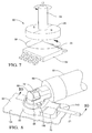
- Figure 8 is a broken, perspective view of an alternative embodiment of the present invention illustrated as installed on a host vehicle;
- Figure 9 is an exploded perspective view of the alternative embodiment of Figure 8 ;
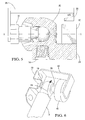
- Figure 10 is a broken, cross-sectional view, on an enlarged scale, of the alternative embodiment of figure 8 , taken on lines 10 - 10 of Figure 8 .
- FIG. 1 schematically illustrates a vehicle 10 having a power rear lift gate 12.
- a jackscrew 14 can be used as the strut 14 to activate the mechanisms for the lift gate 12 to move between opened and closed positions through an included angle "d".
- a conventional jackscrew 14 includes a nut (not shown) supported for reciprocal translational movement and against rotational movement.
- a connector 16 is connected to each end of the jackscrew strut 14 for connecting one end 15 to the vehicle 10 and a second end 17 of the jackscrew strut 14 to the lift gate 12 for accomplishing the raising and lowering of the lift gate 12 and so that certain inherent radial motion of the jackscrew 14 is restricted.
- each connector 16 includes a ball stud 18 mounted to an appropriate location on the vehicle 10 and a ball stud mounting device or ball socket 20 secured to each end of a jackscrew 14.
- a typical application is shown where one ball stud 18 is secured to a bracket 22 at an upper portion of the vehicle 10 adjacent to the opening for the lift gate 12. The other ball stud 18 is mounted to a lower portion of the lift gate 12.
- the mounting configuration can be reversed wherein the connector 16 associated with the upper end of the jackscrew strut 14 is secured to an upper portion of the lift gate 12, and the connector 16 associated with the lower end of the jackscrew strut 14 is secured to a lower portion of the vehicle 10.
- the configuration of the ball socket connector 16 restricts or prevents certain inherent movement of the jackscrew strut 14.
- the inherent movement of the jackscrew strut 14 requires that certain relative movement of the socket connector 16 be restricted or prevented, the movement of the rear lift gate 12 requires certain movement parameters.
- the jackscrew strut 14 for the lift gate 12 should allow at least an 85° angled opening, and preferably a 105° opening about an upper interconnecting hinge point (not illustrated).
- the invention includes providing a sensor 30 for detecting the amount of movement of the ball socket 20 and jackscrew strut 14 relative to the associated ball stud 18 mounted to the vehicle 10 during the opening and closing movements of the lift gate 12.
- the sensor 30 preferably provides signals to an electronic control unit 19.
- the signals are preferably indicative of the amount of movement of the jackscrew strut 14 during the opening and closing of the lift gate 12. It is understood that one can choose from among commercially available electronic control units or specialized circuitry and software to accomplish the signal processing that results in the collection of the desired data.
- a communication link 27 is preferably provided to transmit signals from the sensor 30 to the vehicle electronics control unit 19.
- the lift gate 12 While transitioning between the closed and open positions, the lift gate 12 typically travels (rotates) at approximately 15° per second.
- the preferred position sensor 30 has 1/4 ° resolution. The preferred sensor 30 also detects a full open position within 5° of the actual full open position of the lift gate 12.
- a rotary or angle sensor 30 and a magnet 26 are wherein the magnet 26 is fixedly attached to or carried with the ball stud 16 via rigid support structure 28, and the rotary sensor 30 is connected to the ball socket 20.
- the sensor 30 is supported on the ball socket 20 by a substantially rigid support base 24, which locates the sensor 30 nominally along the centerline X - X of the ball stud 16 in order that the angular rotation of the jackscrew strut 14 relative to the vehicle body 10 can be measured.
- the angle sensor 30 determines the relative jackscrew strut 14 position and provides the information to the electronic control unit 19 via the communication link 27 in order for the electronic control unit 19 to control the power lift gate mechanism (not illustrated).
- An output voltage level indicates the instantaneous position of the jackscrew strut 14 and therefore a separate open switch is not required.
- the senor 40 is a rotary potentiometer 40.
- the potentiometer 40 is fixedly connected to the vehicle body 10 or the bracket 22 by a second bracket 42 so that the potentiometer 40 is operatively connected to the strut socket body 20.
- the jackscrew strut 14 moves through the full travel movement, as indicated by arrow 21, the jackscrew strut 14 will rotate the potentiometer 40 through its operating range.
- the potentiometer 40 provides full open position information to the electronic control unit 19 when powered up.
- the rotary sensor 30 in Figure 5 can be replaced with a rotary position integrated circuit (IC) sensor 50 using a Hall Effect integrated circuit 52 and a magnet 26 to detect absolute position of the strut 14.
- the permanent magnet is carried by structure 54 for limited relative rotation as indicated by arrow ⁇ .
- the radially opposed magnetic poles rotate adjacent the sensing surface 56 of the Hall Effect integrated circuit 52, as indicated by arrow 58, thus conveying the jackscrew strut's instantaneous position information to the electronic control unit 19.
- the integrated circuit 52 can produce a quadrature signal provided as an analog, pulse width module (PWM) or serial data output.
- PWM pulse width module
- the IC 52 provides the position information to the vehicle electronic control unit 19 when powered up including providing a full open position. Therefore a full open switch is not required.
- a position sensor 60 is mountingly interposed between a host vehicle 62 and a jackscrew strut 64.
- a ball socket 66 extends longitudinally from an adjacent end 68 of the jackscrew strut 64.
- the ball socket 66 lockingly engages a steel ball stud 70 for limited pivotal freedom of movement therebetween.
- a spring retainer guideway feature 72 is formed in the ball socket 66.
- the guideway feature 72 positions and retains a spring retainer (not illustrated) which serves to interconnect the ball socket 66 with a head 74 of the ball stud 70 as is described in related copending U.S. patent application identified as Attorney Docket No.: DP-316239, filed 1 February 2008, the specification of which is incorporated herein by reference.
- the ball stud 70 is affixed at a designated mounting location 76 on the outer surface of the vehicle 62 whereby a threaded shank 78 extends through a bore 80 in the mounting location 76 for attachment to a weld nut 82.
- the position sensor 60 includes a stator or housing assembly 83 consisting of a base member 84 and a cover member 86 interconnected by suitable fastening means such as screws 88 extending through registering through holes 90 in the base 84 and blind bores (not illustrated) in the underside of the cover 86. It is contemplated that other alternative forms of attachment, such as ultrasonic welding, snap-fit self engaging cooperating integral features, and the like can also be employed.
- the base 84 has a through passage 92 forming a plurality of symmetrically circumferentially arranged knurls or serrations 94 dimensioned for slip-fit engagement with hex-head flats 96 integrally formed on the outer surface of the ball stud 70.
- the ball stud 70 extends through passage 92 whereupon the knurls 94 engage the radially outwardmost portions of the ball stud flats 96 to rotationally interlock the sensor housing base 84 with the ball stud 70.
- This feature has the advantage of permitting a common design to be employed in many vehicle configurations for both functionality (ex. avoiding interfering with the jackscrew strut through its range of motion) and esthetic reasons.
- the hex-head flats 96 are dual-purpose, and can be employed by an installation tool (ex. wrench, nut driver or the like) for installing the ball stud onto the weld nut 82.
- a rotor or generally annular yoke 98 is disposed within the position sensor housing 83 and extends upwardly through an opening 100 in housing cover 86.
- the exposed upper portion of the yoke 98 has a pocket 102 formed therein for receiving a saddle-shaped radial extension 104 of the ball socket 66.
- a pair of opposed ramped abutment features 106 integrally formed in the radial extension 104 engage cooperating cantilevered engagement members 108 integrally formed in the yoke 98 to maintain engagement between the yoke 98 and the ball socket 66 of the jackscrew strut 64.
- the yoke 98 forms a central through passage 110 concentrically disposed and dimensioned to permit the ball stud 70 to extend upwardly therethrough.
- the yoke 98 has a circumferential flange 112 extending radially outwardly sufficiently to entrap the yoke in assembly within the position sensor housing 83.
- Yoke 98 has a downwardly extending circumferential guide skirt 114 (refer Figure 10 ) integrally formed therewith concentrically with the central through passage 110.
- the yoke guide skirt 114 is in slip-fit juxtaposition radially between concentric inner and outer upwardly extending circumferential guide skirts 116 and 118, respectively, integrally formed on the upper surface of the base member 84.
- the upper surfaces of the inner and outer guide skirts 116 and 118 serve as axial thrust surfaces.
- the base member through passage 92, cover member opening 100 and yoke through passage 110 are precisely axially aligned.
- the yoke is axially and radially constrained within the position sensor housing 83, but is free to rotate with respect thereto about the axis of the ball stud 70.
- a yoke gear 120 is integrally formed on the bottom of the yoke 98 radially outwardly of the yoke guide skirt 114.
- the yoke gear 120 has twenty one (21) symmetrically equally spaced, radially outwardly directed circumferentially equally spaced gear teeth 122.
- the position sensor housing 83 has a localized radial extension 124 formed therein defining a substantially closed inner cavity 126.
- An upwardly extending annular guide skirt 128 is integrally formed within the extension cavity 126.
- An idler gear 130 is disposed within the cavity 126.
- the idler gear 130 has a downwardly directed guide skirt 132 integrally formed therewith which is in slip-fit engagement with the cooperating guide skirt 128.
- the upper surface of the idler gear 130 has a pocket 134 formed therein for nestingly receiving a permanent magnet 136 in a tight interfit to ensure secure fixation therebetween.
- the permanent magnet is preferably radially polarized.
- the idler gear 130 has twelve (12) radially outwardly directed circumferentially equally spaced gear teeth 138.
- the cover member 86 closely abuts the upper surface of the idler gear 130 whereby, in assembly, the idler gear 130 and permanent magnet 136 are axially and radially retained within the position sensor housing 83 but are free to rotate with respect thereto, subject only to the effect of engagement of the idler gear teeth 138 with the yoke gear teeth 122.
- the yoke and idler gears 120 and 130 are configured to rotate about parallel, spaced axes.
- the axes of the gears 120 and 130 are arranged, and gear teeth 122 and 138 are shaped and configured, to ensure continuous intermesh therebetween with no backlash. This will result in precise and repeatable positioning of the permanent magnet 136 in response to irregular and bi-directional inputs through the yoke gear 120.
- the position sensor cover member 86 has a second, substantially closed cavity 140 formed therein configured for receiving and supporting a substrate such as a printed circuit (PCB) board 142.
- An analog absolute position sensor 144 is mechanically supported by the PCB 142 within the cavity 140 and is substantially axially aligned with the permanent magnet 136 (and idler gear 130) through an intermediate web 146 to ensure optimum juxtaposition therebetween.
- the PCB 142 also supports any other electronic or semiconductor devices (not illustrated) as well as the power and/or communication link 27 (refer Figure 1 ), which can have its conductor(s) directly connected to the PCB 142.
- an external access opening 150 in the cover member 86 can be configured to nestingly receive an electrical connector (not illustrated) which is electrically connected to circuit traces and components on the PCB 142. In such an alternative approach, a mating connector plug from a wiring harness lead would be inserted into the connector.
- the base member 84, cover member 86, yoke 98 and idler gear 130 are preferably constructed of non-electrically conductive material such as injection molded plastic.
- the position sensor 60 in application, is integrated into one or both of the ball socket connectors 16 interconnecting the jackscrew strut 14 to a designated mounting location 76 on either a movable panel, such as a lift gate 12, carried on a host vehicle 10, or a relatively fixed portion of the host vehicle 10 itself.
- the embodiment of the position sensor 60 described herein with respect to Figures 8 - 10 has a first portion which is fixedly supported on the host vehicle 10 (either on a relatively non-movable portion of the vehicle's body), or on a movable panel such as a lift gate 12, or both.
- the position sensor 60 has a second portion which is carried for rotation with a jackscrew strut 64. The relative movement or position of the first and second portions is sensed, resulting in an output signal processed by the vehicle ECU to ascertain the instantaneous position of the movable panel.
- the first sensor portion includes the position sensor housing 83, the PCB 142 the analog absolute position sensor 144 and the electrical output conductors 148, which are all affixed to the vehicle 10.
- the second sensor portion includes the yoke 98, the idler gear 130 and the permanent magnet 136, which are affixed to and move with the jackscrew strut 64 as it rotates about the axis X - X extending through the ball stud 70.
- the yoke 98 is guided within the position sensor housing 83 for pure rotation about axis X - X.
- the yoke 98 is interlocked with the ball socket 66 for limited rotation about axis X - X.
- the ramped abutment features 106 of the radial extension 104 of the ball socket 66 serve as pivot points in cooperation with the associated engagement members 108 of the yoke 98 whereby the jackscrew strut 64 is free to rock through a limited range of motion as the associated lift gate 12 translates between its full open and full closed positions.
- the yoke gear 120 moves therewith.
- the yoke gear teeth 122 continuously engage the idler gear teeth 138 to also rotate the idler gear 130 (in a reverse direction) along with the permanent magnet 136.
- the yoke gear has 21 teeth and the idler gear has 12 teeth, whereby the idler gear 130 and magnet 136 rotate at approximately twice the rate of the yoke gear 21. This increases the movement of the permanent magnet 136 with respect to the analog position sensor 144 for a given rotational input to the yoke 98, thereby increasing the resolution and accuracy of the sensing function.
- the gear ratio between the yoke and idler gears can be varied to accommodate differing vehicle lift gate and strut configurations.
Landscapes
- Measurement Of Length, Angles, Or The Like Using Electric Or Magnetic Means (AREA)
- Vehicle Body Suspensions (AREA)
- Power-Operated Mechanisms For Wings (AREA)
Applications Claiming Priority (1)
| Application Number | Priority Date | Filing Date | Title |
|---|---|---|---|
| US12/070,493 US8008910B2 (en) | 2008-02-19 | 2008-02-19 | Strut position sensor including a magnet mounted on an idler gear contained in a stator portion, which is movable relative to a rotor portion connected to the strut, and a galvanomagnetic sensor in the stator portion for detecting angular position of the strut |
Publications (2)
| Publication Number | Publication Date |
|---|---|
| EP2093366A2 true EP2093366A2 (de) | 2009-08-26 |
| EP2093366A3 EP2093366A3 (de) | 2014-04-30 |
Family
ID=40481820
Family Applications (1)
| Application Number | Title | Priority Date | Filing Date |
|---|---|---|---|
| EP09151682.3A Withdrawn EP2093366A3 (de) | 2008-02-19 | 2009-01-29 | Fahrzeugklappenpositionssensor |
Country Status (3)
| Country | Link |
|---|---|
| US (1) | US8008910B2 (de) |
| EP (1) | EP2093366A3 (de) |
| WO (1) | WO2009105519A2 (de) |
Cited By (4)
| Publication number | Priority date | Publication date | Assignee | Title |
|---|---|---|---|---|
| CN107727030A (zh) * | 2017-10-09 | 2018-02-23 | 合肥灵猫传媒有限公司 | 一种汽车车门开度检测方法及装置 |
| CN107764561A (zh) * | 2017-10-09 | 2018-03-06 | 合肥灵猫传媒有限公司 | 一种汽车车门开度检测装置 |
| WO2019072794A1 (de) * | 2017-10-10 | 2019-04-18 | Brose Fahrzeugteile Gmbh & Co. Kommanditgesellschaft, Bamberg | Klappenantriebssystem |
| WO2021121477A1 (de) * | 2019-12-18 | 2021-06-24 | Kiekert Ag | Antriebseinrichtung für kraftfahrzeugtechnische anwendungen |
Families Citing this family (15)
| Publication number | Priority date | Publication date | Assignee | Title |
|---|---|---|---|---|
| US20090196682A1 (en) * | 2008-02-01 | 2009-08-06 | Howard Warren Kuhlman | Bi-directional strut end for ball stud mounted devices |
| JP5241016B2 (ja) * | 2009-01-29 | 2013-07-17 | 矢崎総業株式会社 | 回転コネクタ |
| US8875442B2 (en) * | 2010-03-16 | 2014-11-04 | Strattec Power Access Llc | Method and apparatus of active dampening a powered closure system |
| KR101160521B1 (ko) | 2010-08-27 | 2012-06-28 | 화남전자 주식회사 | 자기 회전식 엔코더 |
| US10688903B2 (en) * | 2014-09-08 | 2020-06-23 | Maxon Industries, Inc. | Light system for lift gates |
| US10443287B2 (en) * | 2015-07-29 | 2019-10-15 | Ford Global Technologies, Llc | Door position sensor and system for a vehicle |
| JP2017065518A (ja) * | 2015-09-30 | 2017-04-06 | アイシン精機株式会社 | 車両用ドア開閉装置 |
| US10343728B2 (en) | 2017-02-16 | 2019-07-09 | Ford Global Technolgies, Llc | Powered hinge assembly and powered tailgate assembly incorporating that powered hinge assembly |
| US10293868B2 (en) | 2017-03-01 | 2019-05-21 | Ford Global Technologies, Llc | Removable tailgate with locking hinge |
| US10731395B2 (en) | 2017-03-15 | 2020-08-04 | Ford Global Technologies, Llc | Smart hinge assembly for a tailgate of a motor vehicle |
| IT201800003563A1 (it) | 2018-03-14 | 2019-09-14 | Claudia Bonetto | Dispositivo di azionamento di emergenza |
| DE102018212959A1 (de) * | 2018-08-02 | 2020-02-06 | Stabilus Gmbh | Schwenkbare Spindelmutter |
| CN113301864B (zh) | 2019-01-31 | 2024-09-17 | 史密夫和内修有限公司 | 用于外部固定支柱测量和实时反馈的装置 |
| DE102019204658A1 (de) * | 2019-04-02 | 2020-10-08 | Zf Friedrichshafen Ag | Verschlusselement für ein Kugelgelenk und Kugelgelenk mit einem solchen Verschlusselement |
| US10928227B2 (en) * | 2019-04-15 | 2021-02-23 | Caterpillar Inc. | Mounting system for mounting a sensor assembly |
Citations (1)
| Publication number | Priority date | Publication date | Assignee | Title |
|---|---|---|---|---|
| US7230419B2 (en) | 2005-06-03 | 2007-06-12 | Delphi Technologies, Inc. | Rotary position sensor |
Family Cites Families (28)
| Publication number | Priority date | Publication date | Assignee | Title |
|---|---|---|---|---|
| SE504230C2 (sv) * | 1995-04-20 | 1996-12-09 | Swedish Control Systems Ab | Mätanordning för detektering av en kulleds vridrörelse runt tre sinsemellan ortogonala axlar |
| US5755526A (en) * | 1996-05-23 | 1998-05-26 | Trw Inc. | Ball and socket joint |
| IT236423Y1 (it) * | 1997-01-29 | 2000-08-17 | Faac Spa | Azionamento perfezionato per la movimentazione di un cancello |
| JPH10246275A (ja) | 1997-02-28 | 1998-09-14 | Kayaba Ind Co Ltd | スティダンパ |
| US5831554A (en) * | 1997-09-08 | 1998-11-03 | Joseph Pollak Corporation | Angular position sensor for pivoted control devices |
| FR2772470B1 (fr) * | 1997-12-12 | 2000-03-10 | Electricfil | Capteur de deplacement rotatif equipe de moyens d'assemblage avec un axe d'entrainement concus pour minimiser les effets d'un desalignement de connexion |
| US6092336A (en) * | 1999-02-11 | 2000-07-25 | Delphi Technologies, Inc. | Power liftgate cable drive with position stop |
| US6316935B1 (en) | 1999-06-08 | 2001-11-13 | Mannesmann Vdo Ag | Sensor of angle of a shaft with a base separating the shaft from a magnetoresistive sensing element |
| JP2002213944A (ja) * | 2001-01-18 | 2002-07-31 | Niles Parts Co Ltd | 回転角測定装置 |
| US6469499B2 (en) * | 2001-02-06 | 2002-10-22 | Delphi Technologies, Inc. | Apparatus and method for low power position sensing systems |
| DE10119340A1 (de) * | 2001-04-20 | 2002-10-31 | Stabilus Gmbh | Betätigungssystem für eine Klappe o. dergleichen |
| US7070226B2 (en) * | 2001-04-26 | 2006-07-04 | Litens Automotive | Powered opening mechanism and control system |
| JP2002331837A (ja) | 2001-05-10 | 2002-11-19 | Ntn Corp | バックドア開閉装置 |
| DE10134259A1 (de) * | 2001-07-18 | 2003-02-06 | Zf Lemfoerder Metallwaren Ag | Kugelgelenk mit integriertem Winkelsensor |
| US7127369B2 (en) * | 2001-10-09 | 2006-10-24 | Siemens Vdo Automotive Corporation | Sensor assembly |
| KR20040001880A (ko) | 2002-06-29 | 2004-01-07 | 가부시키가이샤 미쿠니 | 자기 위치 센서 |
| JP4254212B2 (ja) * | 2002-11-27 | 2009-04-15 | アイシン精機株式会社 | 車両用開閉体の開閉制御システム |
| JP2004191163A (ja) * | 2002-12-11 | 2004-07-08 | Matsushita Electric Ind Co Ltd | 回転角度検出装置 |
| US7080914B1 (en) * | 2003-02-27 | 2006-07-25 | Magna Donnelly Mirrors North America L.L.C. | Vehicular mirror with adjustable pivot connection |
| DE10339126B4 (de) | 2003-08-22 | 2009-04-02 | Zf Friedrichshafen Ag | Kugelgelenk mit Winkelsensor |
| US20060181108A1 (en) * | 2003-09-29 | 2006-08-17 | Cleland Terry P | Low-mounted powered opening system and control mechanism |
| KR100552776B1 (ko) * | 2004-06-04 | 2006-02-20 | 현대자동차주식회사 | 각센서를 이용한 테일 게이트 개폐 제어 장치 및 그 방법 |
| DE102005030052B4 (de) * | 2005-06-27 | 2012-03-08 | Stabilus Gmbh | Antriebseinrichtung |
| US7547058B2 (en) * | 2006-05-15 | 2009-06-16 | Ford Global Technologies, Llc | System and method for operating an automotive liftgate |
| EP1879087A3 (de) * | 2006-07-10 | 2010-08-18 | Brose Schliesssysteme GmbH & Co. KG | Positionserfassungsanordnung für ein motorisch verstellbares Funktionselement in einem Kraftfahrzeug |
| US7710108B2 (en) * | 2007-03-16 | 2010-05-04 | Illinois Tool Works Inc. | Hall effect accelerator module |
| US7570047B2 (en) * | 2007-06-18 | 2009-08-04 | Key Safety Systems, Inc. | Hall effect based angular position sensor |
| US20090196682A1 (en) * | 2008-02-01 | 2009-08-06 | Howard Warren Kuhlman | Bi-directional strut end for ball stud mounted devices |
-
2008
- 2008-02-19 US US12/070,493 patent/US8008910B2/en active Active
-
2009
- 2009-01-29 EP EP09151682.3A patent/EP2093366A3/de not_active Withdrawn
- 2009-02-19 WO PCT/US2009/034487 patent/WO2009105519A2/en not_active Ceased
Patent Citations (1)
| Publication number | Priority date | Publication date | Assignee | Title |
|---|---|---|---|---|
| US7230419B2 (en) | 2005-06-03 | 2007-06-12 | Delphi Technologies, Inc. | Rotary position sensor |
Cited By (4)
| Publication number | Priority date | Publication date | Assignee | Title |
|---|---|---|---|---|
| CN107727030A (zh) * | 2017-10-09 | 2018-02-23 | 合肥灵猫传媒有限公司 | 一种汽车车门开度检测方法及装置 |
| CN107764561A (zh) * | 2017-10-09 | 2018-03-06 | 合肥灵猫传媒有限公司 | 一种汽车车门开度检测装置 |
| WO2019072794A1 (de) * | 2017-10-10 | 2019-04-18 | Brose Fahrzeugteile Gmbh & Co. Kommanditgesellschaft, Bamberg | Klappenantriebssystem |
| WO2021121477A1 (de) * | 2019-12-18 | 2021-06-24 | Kiekert Ag | Antriebseinrichtung für kraftfahrzeugtechnische anwendungen |
Also Published As
| Publication number | Publication date |
|---|---|
| WO2009105519A3 (en) | 2009-12-03 |
| US8008910B2 (en) | 2011-08-30 |
| WO2009105519A2 (en) | 2009-08-27 |
| EP2093366A3 (de) | 2014-04-30 |
| US20090206826A1 (en) | 2009-08-20 |
Similar Documents
| Publication | Publication Date | Title |
|---|---|---|
| US8008910B2 (en) | Strut position sensor including a magnet mounted on an idler gear contained in a stator portion, which is movable relative to a rotor portion connected to the strut, and a galvanomagnetic sensor in the stator portion for detecting angular position of the strut | |
| US7810864B2 (en) | Opening and closing device | |
| US20090100755A1 (en) | Opening/closing device | |
| US8191311B2 (en) | Opening and closing apparatus | |
| US8336255B2 (en) | Opening and closing apparatus | |
| US6377005B1 (en) | Drive device having an actuating drive | |
| US10415999B2 (en) | Rotation angle sensor system and method | |
| CA2675337C (en) | System and method for establishing a reference angle for controlling a vehicle rotational closure system | |
| US8286518B2 (en) | Drive device | |
| EP3351906A1 (de) | Türpositiondetektionsvorrichtung für elektrischen türöffner | |
| EP1553277B1 (de) | Drosselvorrichtung und Fahrzeug | |
| US7780216B2 (en) | Convertible top with a rotational angle detection device | |
| US6094027A (en) | Vehicle memory mirror position transducer | |
| WO2010102237A1 (en) | Absolute position sensor for an automotive powered access panel | |
| US7355365B2 (en) | Functional unit of a motor vehicle | |
| US7752761B2 (en) | Angle measuring arrangement | |
| US20020176181A1 (en) | Sensing mirror position in a powered mirror positioning system | |
| US7010955B2 (en) | Throttle position detecting apparatus | |
| US20090076687A1 (en) | Position detection arrangement for a moveable functional element which can be positioned motor-driven in a motor vehicle | |
| US6304048B1 (en) | Method and device for determining torque in an automotive power window system | |
| CN1701930A (zh) | 配备动作区域检测装置的机器人关节的动作范围限制装置 | |
| CN108495770B (zh) | 具有电动转向锁的转向柱 | |
| US20070289395A1 (en) | Device to determine an absolute rotation angle of a rotary shaft | |
| JP2001088552A (ja) | パワーウインドウ制御装置 | |
| JP2019106889A (ja) | モータ装置 |
Legal Events
| Date | Code | Title | Description |
|---|---|---|---|
| PUAI | Public reference made under article 153(3) epc to a published international application that has entered the european phase |
Free format text: ORIGINAL CODE: 0009012 |
|
| AK | Designated contracting states |
Kind code of ref document: A2 Designated state(s): AT BE BG CH CY CZ DE DK EE ES FI FR GB GR HR HU IE IS IT LI LT LU LV MC MK MT NL NO PL PT RO SE SI SK TR |
|
| AX | Request for extension of the european patent |
Extension state: AL BA RS |
|
| RIC1 | Information provided on ipc code assigned before grant |
Ipc: E05F 15/12 20060101AFI20131202BHEP Ipc: E05F 15/00 20060101ALI20131202BHEP |
|
| PUAL | Search report despatched |
Free format text: ORIGINAL CODE: 0009013 |
|
| AK | Designated contracting states |
Kind code of ref document: A3 Designated state(s): AT BE BG CH CY CZ DE DK EE ES FI FR GB GR HR HU IE IS IT LI LT LU LV MC MK MT NL NO PL PT RO SE SI SK TR |
|
| AX | Request for extension of the european patent |
Extension state: AL BA RS |
|
| RIC1 | Information provided on ipc code assigned before grant |
Ipc: E05F 15/00 20060101ALI20140321BHEP Ipc: E05F 15/12 20060101AFI20140321BHEP |
|
| 17P | Request for examination filed |
Effective date: 20141002 |
|
| RBV | Designated contracting states (corrected) |
Designated state(s): AT BE BG CH CY CZ DE DK EE ES FI FR GB GR HR HU IE IS IT LI LT LU LV MC MK MT NL NO PL PT RO SE SI SK TR |
|
| RBV | Designated contracting states (corrected) |
Designated state(s): AT BE BG CH CY CZ DE DK EE ES FI FR GB GR HR HU IE IS IT LI LT LU LV MC MK MT NL NO PL PT RO SE SI SK TR |
|
| AKX | Designation fees paid |
Designated state(s): DE |
|
| AXX | Extension fees paid |
Extension state: RS Extension state: AL Extension state: BA |
|
| GRAP | Despatch of communication of intention to grant a patent |
Free format text: ORIGINAL CODE: EPIDOSNIGR1 |
|
| RIC1 | Information provided on ipc code assigned before grant |
Ipc: E05F 15/622 20150101AFI20150922BHEP |
|
| INTG | Intention to grant announced |
Effective date: 20151027 |
|
| 17Q | First examination report despatched |
Effective date: 20160208 |
|
| INTC | Intention to grant announced (deleted) | ||
| GRAP | Despatch of communication of intention to grant a patent |
Free format text: ORIGINAL CODE: EPIDOSNIGR1 |
|
| INTG | Intention to grant announced |
Effective date: 20170202 |
|
| STAA | Information on the status of an ep patent application or granted ep patent |
Free format text: STATUS: THE APPLICATION IS DEEMED TO BE WITHDRAWN |
|
| 18D | Application deemed to be withdrawn |
Effective date: 20170613 |
|
| RIC1 | Information provided on ipc code assigned before grant |
Ipc: E05F 15/622 20150101AFI20150922BHEP |
|
| RIC1 | Information provided on ipc code assigned before grant |
Ipc: E05F 15/622 20150101AFI20150922BHEP |