EP2093375A2 - Procédé de réparation de redresseurs en porte-à-faux - Google Patents
Procédé de réparation de redresseurs en porte-à-faux Download PDFInfo
- Publication number
- EP2093375A2 EP2093375A2 EP09250440A EP09250440A EP2093375A2 EP 2093375 A2 EP2093375 A2 EP 2093375A2 EP 09250440 A EP09250440 A EP 09250440A EP 09250440 A EP09250440 A EP 09250440A EP 2093375 A2 EP2093375 A2 EP 2093375A2
- Authority
- EP
- European Patent Office
- Prior art keywords
- vane
- airfoil
- cantilevered stator
- supplemental
- stator vane
- Prior art date
- Legal status (The legal status is an assumption and is not a legal conclusion. Google has not performed a legal analysis and makes no representation as to the accuracy of the status listed.)
- Withdrawn
Links
- 238000000034 method Methods 0.000 title claims abstract description 16
- 230000008439 repair process Effects 0.000 title description 5
- 230000000153 supplemental effect Effects 0.000 claims abstract description 16
- 238000003466 welding Methods 0.000 claims description 8
- 238000002485 combustion reaction Methods 0.000 claims description 3
- 238000009499 grossing Methods 0.000 claims 2
- 238000004140 cleaning Methods 0.000 claims 1
- 238000002156 mixing Methods 0.000 claims 1
- 239000007789 gas Substances 0.000 description 8
- 230000008901 benefit Effects 0.000 description 3
- 238000009659 non-destructive testing Methods 0.000 description 3
- 239000011888 foil Substances 0.000 description 2
- 238000007689 inspection Methods 0.000 description 2
- WFKWXMTUELFFGS-UHFFFAOYSA-N tungsten Chemical compound [W] WFKWXMTUELFFGS-UHFFFAOYSA-N 0.000 description 2
- 229910052721 tungsten Inorganic materials 0.000 description 2
- 239000010937 tungsten Substances 0.000 description 2
- 230000006835 compression Effects 0.000 description 1
- 238000007906 compression Methods 0.000 description 1
- 230000007797 corrosion Effects 0.000 description 1
- 238000005260 corrosion Methods 0.000 description 1
- 230000003628 erosive effect Effects 0.000 description 1
- 239000000446 fuel Substances 0.000 description 1
- 239000011261 inert gas Substances 0.000 description 1
- 238000003754 machining Methods 0.000 description 1
- 238000012986 modification Methods 0.000 description 1
- 230000004048 modification Effects 0.000 description 1
Images

Classifications
-
- F—MECHANICAL ENGINEERING; LIGHTING; HEATING; WEAPONS; BLASTING
- F01—MACHINES OR ENGINES IN GENERAL; ENGINE PLANTS IN GENERAL; STEAM ENGINES
- F01D—NON-POSITIVE DISPLACEMENT MACHINES OR ENGINES, e.g. STEAM TURBINES
- F01D5/00—Blades; Blade-carrying members; Heating, heat-insulating, cooling or antivibration means on the blades or the members
- F01D5/005—Repairing methods or devices
-
- B—PERFORMING OPERATIONS; TRANSPORTING
- B23—MACHINE TOOLS; METAL-WORKING NOT OTHERWISE PROVIDED FOR
- B23P—METAL-WORKING NOT OTHERWISE PROVIDED FOR; COMBINED OPERATIONS; UNIVERSAL MACHINE TOOLS
- B23P6/00—Restoring or reconditioning objects
- B23P6/002—Repairing turbine components, e.g. moving or stationary blades, rotors
- B23P6/005—Repairing turbine components, e.g. moving or stationary blades, rotors using only replacement pieces of a particular form
-
- F—MECHANICAL ENGINEERING; LIGHTING; HEATING; WEAPONS; BLASTING
- F01—MACHINES OR ENGINES IN GENERAL; ENGINE PLANTS IN GENERAL; STEAM ENGINES
- F01D—NON-POSITIVE DISPLACEMENT MACHINES OR ENGINES, e.g. STEAM TURBINES
- F01D9/00—Stators
-
- F—MECHANICAL ENGINEERING; LIGHTING; HEATING; WEAPONS; BLASTING
- F05—INDEXING SCHEMES RELATING TO ENGINES OR PUMPS IN VARIOUS SUBCLASSES OF CLASSES F01-F04
- F05D—INDEXING SCHEME FOR ASPECTS RELATING TO NON-POSITIVE-DISPLACEMENT MACHINES OR ENGINES, GAS-TURBINES OR JET-PROPULSION PLANTS
- F05D2230/00—Manufacture
- F05D2230/20—Manufacture essentially without removing material
- F05D2230/23—Manufacture essentially without removing material by permanently joining parts together
- F05D2230/232—Manufacture essentially without removing material by permanently joining parts together by welding
-
- F—MECHANICAL ENGINEERING; LIGHTING; HEATING; WEAPONS; BLASTING
- F05—INDEXING SCHEMES RELATING TO ENGINES OR PUMPS IN VARIOUS SUBCLASSES OF CLASSES F01-F04
- F05D—INDEXING SCHEME FOR ASPECTS RELATING TO NON-POSITIVE-DISPLACEMENT MACHINES OR ENGINES, GAS-TURBINES OR JET-PROPULSION PLANTS
- F05D2230/00—Manufacture
- F05D2230/80—Repairing, retrofitting or upgrading methods
-
- Y—GENERAL TAGGING OF NEW TECHNOLOGICAL DEVELOPMENTS; GENERAL TAGGING OF CROSS-SECTIONAL TECHNOLOGIES SPANNING OVER SEVERAL SECTIONS OF THE IPC; TECHNICAL SUBJECTS COVERED BY FORMER USPC CROSS-REFERENCE ART COLLECTIONS [XRACs] AND DIGESTS
- Y10—TECHNICAL SUBJECTS COVERED BY FORMER USPC
- Y10T—TECHNICAL SUBJECTS COVERED BY FORMER US CLASSIFICATION
- Y10T29/00—Metal working
- Y10T29/49—Method of mechanical manufacture
- Y10T29/49316—Impeller making
- Y10T29/49318—Repairing or disassembling
Definitions
- This disclosure relates to repairing gas turbine engine components and, more particularly, to repairing a cantilevered stator vane.
- Gas turbine engine components such as turbine blades, turbine vanes, compressor blades, compressor vanes, or other components typically operate in a relatively high stress and high temperature environment.
- the stresses and temperature may result in damage to the component from corrosion, erosion, deformation, or the like.
- the components may be repaired and reused.
- the type of repair process depends on the type of damage. For example, relatively elevated stresses and temperatures within the engine may cause deformation of a blade, vane, or other component. For a vane that is cantilevered, associated stresses may cause twisting of the vane, which could result in cracks being formed in an airfoil portion. Alternatively, a foreign object may enter the gas turbine engine and hit a cantilevered vane causing the vane to become cracked or chipped.
- the cantilevered vanes are configured in vane segments, with one vane segment including a plurality of vanes. When one vane becomes damaged beyond predetermined repair limits, the entire vane segment is generally replaced. Replacement of an entire vane segment is costly compared to repairing individual damaged vanes.
- a method for repairing a cantilevered stator vane having an airfoil supported by a platform includes removing a damaged portion of the airfoil leaving a remaining vane portion. A supplemental airfoil portion is then selected and is attached to the remaining vane portion to provide a repaired cantilevered stator vane.
- the supplemental airfoil portion is welded to the remaining vane portion forming a weld attachment interface. After welding, the weld attachment interface is blended and smoothed out, and is then heat treated.
- the remaining vane portion is smoothed and cleaned prior to attachment of the supplemental air foil portion.
- the damaged portion is removed by cutting across a width of the airfoil.
- the cut is located just beyond the damaged portion, or the airfoil can be cut at a location near the platform. If the cut is just beyond the damaged portion, the supplemental airfoil portion is cut to the proper length and is then attached to the remaining vane portion.
- Figure 1 is a highly schematic view of a turbine engine.
- Figure 2 is a cross-sectional view of a compressor section of the turbine engine.
- Figure 3 is a schematic representation of a damaged cantilevered stator vane.
- Figure 4 is a schematic representation of a repaired cantilevered stator vane.
- Figure 1 illustrates selected portions of an example turbine engine 10, such as a gas turbine engine used for propulsion.
- the turbine engine 10 is circumferentially disposed about an engine centerline 12.
- the turbine engine 10 includes a fan 14, a compressor section 16, a combustion section 18, and a turbine section 20.
- the compressor section 16 and the turbine section 20 include corresponding blades 22 and stator vanes 24.
- air compressed in the compressor section 16 is mixed with fuel and burned in the combustion section 18 to produce hot gasses that are expanded in the turbine section 20.
- Figure 1 is a highly schematic presentation for illustrative purposes only and is not a limitation on the disclosed examples. Additionally, there are various types of gas turbine engines, many of which could benefit from the examples disclosed herein and are not limited to the designs shown.
- a gas turbine engine may contain a gearbox disposed between the turbine section 20 and the fan 14, allowing the fan 14 to turn at a different speed than the turbine.
- the compressor section 16 can include low pressure and high pressure sections with a combination of blades and disks that are coupled to rotate about the engine centerline 12.
- the gas turbine engine may be used to turn an electrical generator instead of being used for propulsion.
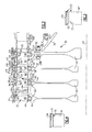
- Figure 2 illustrates a more detailed example of the compressor section 16, and specifically shows a high pressure section 30 of the compressor. It should be understood that only the upper cross-section of the high pressure section 30 is shown in Figure 2 , with the lower cross-section being similarly configured to that of the upper cross-section as the compressor includes a component that circumscribes the engine centerline 12. It should also be understood that the following description is also applicable to a low pressure section of the compressor section 16.
- the high pressure section 30 includes a plurality of high pressure compressor (HPC) disks 32 that are mounted to rotate with a main shaft 34 ( Figure 1 ) about the engine centerline 12.
- HPC high pressure compressor
- an attachment structure 36 which is mounted for rotation with the main shaft 34, is used to attach the HPC disks 32 to the main shaft 34.
- a support structure 38 has a portion that extends in a direction that is generally parallel to the engine centerline 12.
- One end of each of the HPC disks 32 is secured to the support structure 38, and the HPC disks 32 extend radially inwardly to distal ends that are positioned adjacent to the main shaft 34.
- the blades 22 of the high pressure section 30 each have one end secured to the support structure 38 and extend radially outward to distal ends that are positioned adjacent to an outer shroud portion 40 and/or engine casing 42.
- Each of the blades 22 has a root portion 44 that extends radially inward from a platform 46 in a direction toward the engine centerline 12.
- Each blade 22 also includes an airfoil portion 48 that extends radially outward from the platform 46 in a direction away from the engine centerline 12.
- the root portion 44 is secured within a recess 50 formed in the support structure 38.
- the stator vanes 24 of the high pressure section 30 comprise cantilevered stator vanes 24 that each extends radially inward to distal ends that are positioned near the support structure 38.
- the cantilevered stator vanes 24 each include one outer shroud portion 40, an airfoil portion 52, and a platform 54.
- the airfoil portion 52 has one end fixed to the outer shroud portion 40 and extends radially inward from the platform 54 toward the engine centerline 12.
- the outer shroud portion 40 includes feet 56 that extend in an axial direction and contact the engine casing 42. A plurality of vanes are fixed to the same outer shroud portion to form a vane segment.
- the outer air seal 58 cooperates with the feet 56 to hold the outer shroud portion 40 in place against the engine casing 42.
- the outer air seal 58 includes a first axially extending portion 60 that engages one foot 56a on one outer shroud portion 40 for a first cantilevered stator 24a and a second axially extending portion 62 that engages another foot 56b on the outer shroud portion 40 for a second cantilevered stator 24b that is positioned adjacent to the first cantilevered stator 24a.
- One blade 22 is positioned between the first 24a and second 24b cantilevered stators to provide an alternating pattern of blades 22 and vanes 24.
- the outer air seal 58 also includes a flange portion 64 that extends radially outward in a direction away from the engine centerline 12. The flange portion 64 extends between portions of the engine casing 42 to facilitate providing a sealed interface.
- feet 56 may also be held by an inner diameter of the engine casing 42 in slots formed similar to those provided by outer air seal foot portions 56a and 56b.
- the slots in the inner diameter of the engine casing 42 position the cantilevered stator vanes 24 both axially and radially.
- the airfoil portion 52 of one of the cantilevered stator vanes 24 becomes damaged, the airfoil portion 52 may be repaired by replacing only the damaged air foil portion 52'. In other words, the entire vane segment of stator vanes does not have to be replaced; only the damaged portion of the single vane is repaired. If the airfoil portion 52 is damaged at a point indicated at 70 ( Figure 3 ), the damaged airfoil portion 52' is removed from the vane segment at an airfoil location that is radially outward of the damage point 70, or at an airfoil location that is at or near a junction of the airfoil portion 52 to the platform 54.
- the damaged airfoil portion 52' may be separated from the vane segment by cutting the airfoil portion 52 across an entire width thereof.
- the airfoil portion 52 may be cut using an electric discharge machine (EDM) process or other machining processes.
- EDM electric discharge machine
- the remaining portion 72 see Figure 3
- a new or supplemental airfoil portion 74 ( Figure 4 ) is then selected and welded to the remaining portion 72.
- An exemplary supplemental airfoil portion 74 has a complete airfoil cross-section and is in the form of a length of finished-shape vane extending from a tip thereof towards but not including a platform thereof.
- the supplemental airfoil portion 74 is cut to a desired length and is then welded to the remaining portion 72.
- a linear friction welder, gas tungsten arc welding ( GTAW ), which is also known as tungsten inert gas (TIG) welding, or other welding methods are used to secure the supplemental airfoil portion 74 to the remaining portion 72 of the original airfoil portion 52 at a weld interface 76.
- GTAW gas tungsten arc welding
- TOG tungsten inert gas
- This welding process is similar to welding processes for integrated blade rotors (IBRs).
- the weld interface 76 is blended and smoothed and the repaired component is heat treated in a known manner for weld interfaces.
- the repaired component then undergoes nondestructive testing (NDT) such as fluorescent penetrant inspection (FPI) and X-ray inspection, for example. Once NDT has been satisfied, the repaired component can then be reinstalled in the turbine engine 10. Using this repair process provides significant cost savings as opposed to replacing the entire component.
- NDT nondestructive testing
Landscapes
- Engineering & Computer Science (AREA)
- Mechanical Engineering (AREA)
- General Engineering & Computer Science (AREA)
- Structures Of Non-Positive Displacement Pumps (AREA)
- Manufacture Of Motors, Generators (AREA)
Applications Claiming Priority (1)
| Application Number | Priority Date | Filing Date | Title |
|---|---|---|---|
| US12/034,725 US20090214335A1 (en) | 2008-02-21 | 2008-02-21 | Method of repair for cantilevered stators |
Publications (2)
| Publication Number | Publication Date |
|---|---|
| EP2093375A2 true EP2093375A2 (fr) | 2009-08-26 |
| EP2093375A3 EP2093375A3 (fr) | 2012-10-03 |
Family
ID=40456290
Family Applications (1)
| Application Number | Title | Priority Date | Filing Date |
|---|---|---|---|
| EP09250440A Withdrawn EP2093375A3 (fr) | 2008-02-21 | 2009-02-20 | Procédé de réparation de redresseurs en porte-à-faux |
Country Status (2)
| Country | Link |
|---|---|
| US (1) | US20090214335A1 (fr) |
| EP (1) | EP2093375A3 (fr) |
Cited By (1)
| Publication number | Priority date | Publication date | Assignee | Title |
|---|---|---|---|---|
| WO2019212533A1 (fr) * | 2018-05-01 | 2019-11-07 | Siemens Energy, Inc. | Fabrication et réparation hybrides de composants |
Families Citing this family (4)
| Publication number | Priority date | Publication date | Assignee | Title |
|---|---|---|---|---|
| US8763403B2 (en) | 2010-11-19 | 2014-07-01 | United Technologies Corporation | Method for use with annular gas turbine engine component |
| WO2014189564A2 (fr) | 2013-03-06 | 2014-11-27 | United Technologies Corporation | Rotor comportant une prétranchée pour turbine à gaz |
| WO2015038637A1 (fr) * | 2013-09-13 | 2015-03-19 | United Technologies Corporation | Réparation ou remise en état de joints d'étanchéité à l'air extérieur d'aube pour moteur à turbine à gaz |
| US12173615B2 (en) * | 2020-02-14 | 2024-12-24 | Rtx Corporation | Multi-zone blade fabrication |
Citations (4)
| Publication number | Priority date | Publication date | Assignee | Title |
|---|---|---|---|---|
| US6238187B1 (en) | 1999-10-14 | 2001-05-29 | Lsp Technologies, Inc. | Method using laser shock peening to process airfoil weld repairs pertaining to blade cut and weld techniques |
| EP1231010A1 (fr) | 2001-02-08 | 2002-08-14 | Siemens Westinghouse Power Corporation | Réparation d'aubes de turbines par assemblage en phase liquide transitoire |
| EP1533071A2 (fr) | 2003-11-14 | 2005-05-25 | General Electric Company | Méthode de réparation d'aubes de rotor d'une turbomachine |
| DE102005019077A1 (de) | 2005-04-23 | 2006-10-26 | Mtu Aero Engines Gmbh | Schaufel einer Strömungsmaschine und Verfahren zur Herstellung und/oder Reparatur derselben |
Family Cites Families (16)
| Publication number | Priority date | Publication date | Assignee | Title |
|---|---|---|---|---|
| US4305697A (en) * | 1980-03-19 | 1981-12-15 | General Electric Company | Method and replacement member for repairing a gas turbine engine vane assembly |
| US5755031A (en) * | 1996-11-12 | 1998-05-26 | United Technologies Corporation | Method for attaching a rotor blade to an integrally bladed rotor |
| US5865364A (en) * | 1996-12-24 | 1999-02-02 | United Technologies Corporation | Process for linear friction welding |
| US6098871A (en) * | 1997-07-22 | 2000-08-08 | United Technologies Corporation | Process for bonding metallic members using localized rapid heating |
| US6219916B1 (en) * | 1997-12-19 | 2001-04-24 | United Technologies Corporation | Method for linear friction welding and product made by such method |
| US6339878B1 (en) * | 2000-03-27 | 2002-01-22 | United Technologies Corporation | Method of repairing an airfoil |
| US6568077B1 (en) * | 2000-05-11 | 2003-05-27 | General Electric Company | Blisk weld repair |
| US6532656B1 (en) * | 2001-10-10 | 2003-03-18 | General Electric Company | Gas turbine engine compressor blade restoration method |
| US6688512B2 (en) * | 2001-12-20 | 2004-02-10 | United Technologies Corporation | Apparatus and method for friction welding |
| US7651319B2 (en) * | 2002-02-22 | 2010-01-26 | Drs Power Technology Inc. | Compressor stator vane |
| US6984108B2 (en) * | 2002-02-22 | 2006-01-10 | Drs Power Technology Inc. | Compressor stator vane |
| US7146725B2 (en) * | 2003-05-06 | 2006-12-12 | Siemens Power Generation, Inc. | Repair of combustion turbine components |
| GB0412775D0 (en) * | 2004-06-09 | 2004-07-07 | Rolls Royce Plc | Method of replacing damaged aerofoil |
| US7587818B2 (en) * | 2004-12-23 | 2009-09-15 | General Electric Company | Repair of gas turbine blade tip without recoating the repaired blade tip |
| US20060260125A1 (en) * | 2005-05-18 | 2006-11-23 | Arnold James E | Method for repairing a gas turbine engine airfoil part using a kinetic metallization process |
| US7530791B2 (en) * | 2005-12-22 | 2009-05-12 | Pratt & Whitney Canada Corp. | Turbine blade retaining apparatus |
-
2008
- 2008-02-21 US US12/034,725 patent/US20090214335A1/en not_active Abandoned
-
2009
- 2009-02-20 EP EP09250440A patent/EP2093375A3/fr not_active Withdrawn
Patent Citations (4)
| Publication number | Priority date | Publication date | Assignee | Title |
|---|---|---|---|---|
| US6238187B1 (en) | 1999-10-14 | 2001-05-29 | Lsp Technologies, Inc. | Method using laser shock peening to process airfoil weld repairs pertaining to blade cut and weld techniques |
| EP1231010A1 (fr) | 2001-02-08 | 2002-08-14 | Siemens Westinghouse Power Corporation | Réparation d'aubes de turbines par assemblage en phase liquide transitoire |
| EP1533071A2 (fr) | 2003-11-14 | 2005-05-25 | General Electric Company | Méthode de réparation d'aubes de rotor d'une turbomachine |
| DE102005019077A1 (de) | 2005-04-23 | 2006-10-26 | Mtu Aero Engines Gmbh | Schaufel einer Strömungsmaschine und Verfahren zur Herstellung und/oder Reparatur derselben |
Cited By (1)
| Publication number | Priority date | Publication date | Assignee | Title |
|---|---|---|---|---|
| WO2019212533A1 (fr) * | 2018-05-01 | 2019-11-07 | Siemens Energy, Inc. | Fabrication et réparation hybrides de composants |
Also Published As
| Publication number | Publication date |
|---|---|
| EP2093375A3 (fr) | 2012-10-03 |
| US20090214335A1 (en) | 2009-08-27 |
Similar Documents
| Publication | Publication Date | Title |
|---|---|---|
| US10213883B2 (en) | System and method for in situ repair of gas turbine engine casing clearance | |
| US20180216464A1 (en) | Method of repairing a blisk | |
| CN103084780B (zh) | 用于维修涡轮叶片顶部的方法 | |
| EP2161408A2 (fr) | Aubes d'écran thermique réparées pour entretoise d'échappement de turbine et procédés de réparation | |
| US20090047132A1 (en) | Durable blade | |
| EP2116691A2 (fr) | Procédé de réparation d'un composant d'une turbine à gaz | |
| US9694440B2 (en) | Support collar geometry for linear friction welding | |
| US8479391B2 (en) | Consumable collar for linear friction welding of blade replacement for damaged integrally bladed rotors | |
| US9102014B2 (en) | Method of servicing an airfoil assembly for use in a gas turbine engine | |
| US9567860B2 (en) | Fixture for an airfoil shroud and method for modifying an airfoil shroud | |
| EP2159371B1 (fr) | Ensemble aubes de turbine à gaz et procédés de réparation | |
| EP2093375A2 (fr) | Procédé de réparation de redresseurs en porte-à-faux | |
| EP2735704A2 (fr) | Procédé pour modifier un plateau de connexion d'aube à aube et aube | |
| EP3318364A1 (fr) | Coupon fileté pour réparation de pièces en superalliage | |
| JP2009041449A (ja) | ガスタービン動翼の補修方法 | |
| EP1564371A2 (fr) | Procédé pour la réparation de pièce coulée | |
| JP7106267B2 (ja) | シュラウドを改修するための方法およびブレード | |
| US20160362988A1 (en) | Method for modifying an airfoil shroud and airfoil | |
| US10563533B2 (en) | Repair or remanufacture of blade outer air seals for a gas turbine engine | |
| US20140147284A1 (en) | Method for modifying an airfoil shroud | |
| US11814979B1 (en) | Systems and methods of hybrid blade tip repair | |
| EP3163015A1 (fr) | Réparation de buse de puissance avec matériel de refroidissement installé |
Legal Events
| Date | Code | Title | Description |
|---|---|---|---|
| PUAI | Public reference made under article 153(3) epc to a published international application that has entered the european phase |
Free format text: ORIGINAL CODE: 0009012 |
|
| AK | Designated contracting states |
Kind code of ref document: A2 Designated state(s): AT BE BG CH CY CZ DE DK EE ES FI FR GB GR HR HU IE IS IT LI LT LU LV MC MK MT NL NO PL PT RO SE SI SK TR |
|
| AX | Request for extension of the european patent |
Extension state: AL BA RS |
|
| PUAL | Search report despatched |
Free format text: ORIGINAL CODE: 0009013 |
|
| AK | Designated contracting states |
Kind code of ref document: A3 Designated state(s): AT BE BG CH CY CZ DE DK EE ES FI FR GB GR HR HU IE IS IT LI LT LU LV MC MK MT NL NO PL PT RO SE SI SK TR |
|
| AX | Request for extension of the european patent |
Extension state: AL BA RS |
|
| RIC1 | Information provided on ipc code assigned before grant |
Ipc: F01D 5/00 20060101AFI20120824BHEP |
|
| 17P | Request for examination filed |
Effective date: 20130403 |
|
| AKX | Designation fees paid |
Designated state(s): DE GB |
|
| 17Q | First examination report despatched |
Effective date: 20140331 |
|
| STAA | Information on the status of an ep patent application or granted ep patent |
Free format text: STATUS: THE APPLICATION IS DEEMED TO BE WITHDRAWN |
|
| 18D | Application deemed to be withdrawn |
Effective date: 20141011 |