EP2093379A2 - Ensemble à buse variable pour turbocompresseur - Google Patents
Ensemble à buse variable pour turbocompresseur Download PDFInfo
- Publication number
- EP2093379A2 EP2093379A2 EP09152416A EP09152416A EP2093379A2 EP 2093379 A2 EP2093379 A2 EP 2093379A2 EP 09152416 A EP09152416 A EP 09152416A EP 09152416 A EP09152416 A EP 09152416A EP 2093379 A2 EP2093379 A2 EP 2093379A2
- Authority
- EP
- European Patent Office
- Prior art keywords
- nozzle
- nozzle portion
- variable
- holes
- recesses
- Prior art date
- Legal status (The legal status is an assumption and is not a legal conclusion. Google has not performed a legal analysis and makes no representation as to the accuracy of the status listed.)
- Granted
Links
- 125000006850 spacer group Chemical group 0.000 claims abstract description 24
- 230000001105 regulatory effect Effects 0.000 claims description 8
- 230000035515 penetration Effects 0.000 abstract description 18
- 239000007789 gas Substances 0.000 description 12
- 239000002184 metal Substances 0.000 description 8
- 230000007246 mechanism Effects 0.000 description 5
- 239000003570 air Substances 0.000 description 4
- 230000000694 effects Effects 0.000 description 3
- 229910000963 austenitic stainless steel Inorganic materials 0.000 description 2
- 230000006872 improvement Effects 0.000 description 2
- 238000000034 method Methods 0.000 description 2
- 238000012986 modification Methods 0.000 description 2
- 230000004048 modification Effects 0.000 description 2
- 230000008569 process Effects 0.000 description 2
- 238000003466 welding Methods 0.000 description 2
- 239000012080 ambient air Substances 0.000 description 1
- 230000008901 benefit Effects 0.000 description 1
- 230000015556 catabolic process Effects 0.000 description 1
- 238000002485 combustion reaction Methods 0.000 description 1
- 230000001276 controlling effect Effects 0.000 description 1
- 238000006731 degradation reaction Methods 0.000 description 1
- 230000002939 deleterious effect Effects 0.000 description 1
- 239000000284 extract Substances 0.000 description 1
- 238000005242 forging Methods 0.000 description 1
- 239000000446 fuel Substances 0.000 description 1
- 230000004927 fusion Effects 0.000 description 1
- 238000003754 machining Methods 0.000 description 1
- 239000000463 material Substances 0.000 description 1
- 230000008646 thermal stress Effects 0.000 description 1
Images


Classifications
-
- F—MECHANICAL ENGINEERING; LIGHTING; HEATING; WEAPONS; BLASTING
- F01—MACHINES OR ENGINES IN GENERAL; ENGINE PLANTS IN GENERAL; STEAM ENGINES
- F01D—NON-POSITIVE DISPLACEMENT MACHINES OR ENGINES, e.g. STEAM TURBINES
- F01D9/00—Stators
- F01D9/02—Nozzles; Nozzle boxes; Stator blades; Guide conduits, e.g. individual nozzles
- F01D9/026—Scrolls for radial machines or engines
-
- F—MECHANICAL ENGINEERING; LIGHTING; HEATING; WEAPONS; BLASTING
- F01—MACHINES OR ENGINES IN GENERAL; ENGINE PLANTS IN GENERAL; STEAM ENGINES
- F01D—NON-POSITIVE DISPLACEMENT MACHINES OR ENGINES, e.g. STEAM TURBINES
- F01D17/00—Regulating or controlling by varying flow
- F01D17/10—Final actuators
- F01D17/12—Final actuators arranged in stator parts
- F01D17/14—Final actuators arranged in stator parts varying effective cross-sectional area of nozzles or guide conduits
- F01D17/16—Final actuators arranged in stator parts varying effective cross-sectional area of nozzles or guide conduits by means of nozzle vanes
- F01D17/165—Final actuators arranged in stator parts varying effective cross-sectional area of nozzles or guide conduits by means of nozzle vanes for radial flow, i.e. the vanes turning around axes which are essentially parallel to the rotor centre line
-
- F—MECHANICAL ENGINEERING; LIGHTING; HEATING; WEAPONS; BLASTING
- F01—MACHINES OR ENGINES IN GENERAL; ENGINE PLANTS IN GENERAL; STEAM ENGINES
- F01D—NON-POSITIVE DISPLACEMENT MACHINES OR ENGINES, e.g. STEAM TURBINES
- F01D25/00—Component parts, details, or accessories, not provided for in, or of interest apart from, other groups
- F01D25/24—Casings; Casing parts, e.g. diaphragms, casing fastenings
- F01D25/246—Fastening of diaphragms or stator-rings
-
- F—MECHANICAL ENGINEERING; LIGHTING; HEATING; WEAPONS; BLASTING
- F05—INDEXING SCHEMES RELATING TO ENGINES OR PUMPS IN VARIOUS SUBCLASSES OF CLASSES F01-F04
- F05D—INDEXING SCHEME FOR ASPECTS RELATING TO NON-POSITIVE-DISPLACEMENT MACHINES OR ENGINES, GAS-TURBINES OR JET-PROPULSION PLANTS
- F05D2220/00—Application
- F05D2220/40—Application in turbochargers
-
- F—MECHANICAL ENGINEERING; LIGHTING; HEATING; WEAPONS; BLASTING
- F05—INDEXING SCHEMES RELATING TO ENGINES OR PUMPS IN VARIOUS SUBCLASSES OF CLASSES F01-F04
- F05D—INDEXING SCHEME FOR ASPECTS RELATING TO NON-POSITIVE-DISPLACEMENT MACHINES OR ENGINES, GAS-TURBINES OR JET-PROPULSION PLANTS
- F05D2230/00—Manufacture
- F05D2230/20—Manufacture essentially without removing material
- F05D2230/23—Manufacture essentially without removing material by permanently joining parts together
- F05D2230/232—Manufacture essentially without removing material by permanently joining parts together by welding
-
- F—MECHANICAL ENGINEERING; LIGHTING; HEATING; WEAPONS; BLASTING
- F05—INDEXING SCHEMES RELATING TO ENGINES OR PUMPS IN VARIOUS SUBCLASSES OF CLASSES F01-F04
- F05D—INDEXING SCHEME FOR ASPECTS RELATING TO NON-POSITIVE-DISPLACEMENT MACHINES OR ENGINES, GAS-TURBINES OR JET-PROPULSION PLANTS
- F05D2230/00—Manufacture
- F05D2230/60—Assembly methods
- F05D2230/64—Assembly methods using positioning or alignment devices for aligning or centring, e.g. pins
Definitions
- the present invention relates to turbochargers having a variable-nozzle turbine in which an array of movable vanes is disposed in the nozzle of the turbine for regulating exhaust gas flow into the turbine.
- An exhaust gas-driven turbocharger is a device used in conjunction with an internal combustion engine for increasing the power output of the engine by compressing the air that is delivered to the air intake of the engine to be mixed with fuel and burned in the engine.
- a turbocharger comprises a compressor wheel mounted on one end of a shaft in a compressor housing and a turbine wheel mounted on the other end of the shaft in a turbine housing.
- the turbine housing is formed separately from the compressor housing, and there is yet another center housing connected between the turbine and compressor housings for containing bearings for the shaft.
- the turbine housing defines a generally annular chamber that surrounds the turbine wheel and that receives exhaust gas from an engine.
- the turbine assembly includes a nozzle that leads from the chamber into the turbine wheel.
- the exhaust gas flows from the chamber through the nozzle to the turbine wheel and the turbine wheel is driven by the exhaust gas.
- the turbine thus extracts power from the exhaust gas and drives the compressor.
- the compressor receives ambient air through an inlet of the compressor housing and the air is compressed by the compressor wheel and is then discharged from the housing to the engine air intake.
- variable-geometry turbocharger which includes an array of variable vanes in the turbine nozzle. The vanes are pivotally mounted in the nozzle and are connected to a mechanism that enables the setting angles of the vanes to be varied.
- Changing the setting angles of the vanes has the effect of changing the effective flow area in the turbine nozzle, and thus the flow of exhaust gas to the turbine wheel can be regulated by controlling the vane positions. In this manner, the power output of the turbine can be regulated, which allows engine power output to be controlled to a greater extent than is generally possible with a fixed-geometry turbocharger.
- variable vane mechanism is relatively complicated and thus presents a challenge in terms of assembly of the turbocharger. Furthermore, the mechanism is located between the turbine housing, which gets quite hot because of its exposure to exhaust gases, and the center housing, which is at a much lower temperature than the turbine housing. Accordingly, the variable vane mechanism is subject to thermal stresses because of this temperature gradient.
- variable-nozzle turbocharger that includes a cartridge containing the variable vane mechanism.
- the turbine defines a nozzle through which exhaust gas is delivered to the turbine wheel, and a central bore through which exhaust gas is discharged after it passes through the turbine wheel.
- the cartridge is connected between the center housing and the turbine housing and comprises an assembly of a generally annular nozzle ring and an array of vanes circumferentially spaced about the nozzle ring and rotatably mounted to the nozzle ring and connected to a rotatable actuator ring such that rotation of the actuator ring rotates the vanes for regulating exhaust gas flow to the turbine wheel.
- the cartridge also includes an insert having a tubular portion sealingly received into the bore of the turbine housing and having a nozzle portion extending generally radially out from one end of the tubular portion, the nozzle portion being axially spaced from the nozzle ring such that the vanes extend between the nozzle ring and the nozzle portion.
- a plurality of spacers are connected between the nozzle portion of the insert and the nozzle ring for securing the nozzle ring to the insert and maintaining an axial spacing between the nozzle portion of the insert and the nozzle ring.
- the spacers are welded to the nozzle portion of the insert.
- a variable-nozzle assembly in a turbocharger generally of the type described above, comprises a generally annular nozzle ring and an array of vanes circumferentially spaced about the nozzle ring and rotatably mounted to the nozzle ring such that the vanes are variable in setting angle for regulating exhaust gas flow therethrough, and an insert having a tubular portion and having an annular nozzle portion extending generally radially out from one end of the tubular portion.
- the nozzle portion has a substantially planar first surface facing axially toward the nozzle ring and an opposite substantially planar second surface.
- the insert defines a plurality of axially extending holes extending entirely through a thickness of the nozzle portion defined between the first and second surfaces, the holes being spaced apart from one another along a circumferential direction of the nozzle portion and being proximate a radially outer edge of the nozzle portion.
- the assembly further comprises a plurality of spacers circumferentially spaced apart and having first ends joined to the nozzle ring, opposite second ends of the spacers engaged in the holes in the nozzle portion of the insert and secured to the nozzle portion by welds formed at the second surface.
- An annular groove is defined in the second surface of the nozzle portion and is located radially inward of and proximate to the holes, the groove extending partially through the thickness of the nozzle portion.
- the provision of the groove in the nozzle portion is effective to reduce the mass of metal adjacent the radially inner side of each hole, so that the weld penetration achieved in this area is comparable to or at least closer to the degree of penetration achieved at the radially outer side of the hole near the outer edge of the nozzle portion.
- the nozzle portion can have a pair of recesses defined in the second surface, the recesses being spaced on opposite sides of each hole.
- the recesses extend partially through the thickness of the nozzle portion. The recesses reduce the mass of metal adjacent the sides of the hole so as to facilitate greater weld penetration in these areas.
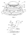
- FIG. 1 is a perspective view of a variable-nozzle assembly that does not include the features of the present invention
- FIG. 2 is a cross-sectional view of a portion of the assembly of FIG. 1 ;
- FIG. 3 is a magnified photograph of a weld produced in a variable-nozzle assembly generally as shown in FIG. 1 , the weld being sectioned along a radial-axial plane of the assembly;
- FIG. 4 is a perspective view of a variable-nozzle assembly in accordance with one embodiment of the invention.
- FIG. 5 is a cross-sectional view of a portion of the assembly of FIG. 4 ;
- FIG. 6 is a magnified photograph of a weld produced in a variable-nozzle assembly having an annular groove in accordance with the invention, the weld being sectioned along a radial-axial plane of the assembly;
- FIG. 7 is a magnified photograph of a weld produced in a variable-nozzle assembly having an annular groove plus two recesses generally as shown in FIG. 4 , the weld being sectioned along a radial-axial plane of the assembly.
- variable-nozzle assembly 100 generally as shown in FIGS. 1 and 2 .
- This variable-nozzle assembly is formed by a generally annular nozzle ring 110 , which supports a plurality of vanes 120 circumferentially spaced about the nozzle ring.
- the vanes are rotatably journaled in the nozzle ring in known fashion so that the setting angles of the vanes can be varied for regulating flow through the nozzle.
- the variable-nozzle assembly further comprises an insert 130 having a tubular portion 132 configured to be inserted into an axial bore of a turbine housing.
- the insert also has an annular nozzle portion 134 joined to one end of the tubular portion 132 and extending radially outwardly therefrom.
- the nozzle portion has a substantially planar first surface 136 axially facing and spaced from the nozzle ring 110 and a substantially planar second surface 138 facing away from the nozzle ring.
- the vanes 120 are disposed between the nozzle ring and the nozzle portion of the insert.
- the vanes have vane arms (not visible) that are adjacent an opposite side of the nozzle ring from the insert, and the vane arms are engaged by a rotatable unison ring 125 . Rotation of the unison ring pivots the vanes about their respective axes.
- the nozzle portion 134 is secured to the nozzle ring 110 by a plurality of spacers 140 (three in number, in the illustrated embodiment) that are circumferentially spaced apart and that extend axially between the nozzle portion and nozzle ring.
- Each spacer has a middle portion of relatively greater diameter, and opposite first and second end portions that are smaller in diameter than the middle portion and are cylindrical in form.
- the first end portion is secured in any suitable fashion in a hole 112 formed in the nozzle ring, and the second end portion passes through a hole 142 formed in the nozzle portion 134 .
- the holes 112 , 142 are smaller in diameter than the middle portion of the spacer, such that the middle portion abuts the facing surfaces of the nozzle ring and nozzle portion and keeps them spaced by an axial distance dictated by the middle portion of the spacer.
- the second end portion of the spacer has a length about equal to the thickness of the nozzle portion 134 such that the tip of the spacer is approximately flush with the second surface 138 .
- the second end portion of the spacer is secured to the nozzle portion by a weld made at the second surface.
- a weld was produced in this manner and thereafter was sectioned along a radial-axial plane and photographed.
- the weld was produced by a PTW 150 plasma arc torch supplied by L-TEC Sch spatechnik GmbH of Hor, Germany.
- the weld temperature was about 1600 to 2000 °C, and the weld process was an autogenous process (i.e., there was no added weld material).
- the spacer 140 was made of AISI316L (an austenitic stainless steel) and was manufactured by turning, and the insert 130 was made of AISI309 (an austenitic stainless steel) and was manufactured by hot forging and machining.
- An enlarged photograph of the sectioned weld is shown in FIG. 3 .
- FIGS. 4 and 5 a variable-nozzle assembly 200 in accordance with one embodiment of the invention is shown in FIGS. 4 and 5 .
- the assembly includes the same nozzle ring 110 , vanes 120 , and spacers 140 as in the FIG. 1 embodiment, and thus the descriptions of these parts are not repeated here.
- the assembly 200 differs from the prior assembly in that the insert 230 is modified relative to the insert 130 .
- the insert 230 includes a tubular portion 232 generally as previously described.
- the nozzle portion 234 of the insert still has the substantially planar first surface 236 and substantially planar second surface 238 , and includes holes 242 for the second end portions of the spacers 140 .
- the second surface 238 has an annular groove 250 formed therein, extending partially through the thickness of the nozzle portion 234 .
- the groove is located just radially inwardly of the holes 242 .
- a radial distance between the radially inner edges of the holes 242 and the radially outer edge of the groove 250 can be approximately equal to the radial distance between the radially outer edges of the holes 242 and the radially outer edge of the nozzle portion.
- this spacing distance can be about 0.3 to 0.7 times the diameter of the holes 242 , although the invention is not limited in this sense.
- the radial width of the groove 250 can be about 0.5 to 1.0 times the diameter of the holes 242 , although again the invention is not limited in this way.
- the second surface 238 of the nozzle portion 234 can also include a pair of recesses 260 associated with each hole 242 .
- the recesses 260 are spaced on opposite sides of each hole 242 in the circumferential direction, and extend partially through the thickness of the nozzle portion.
- Each of the recesses can be spaced from the associated hole 242 by a circumferential distance about equal to the radial distance between the radially outer edges of the holes 242 and the radially outer edge of the nozzle portion. Generally, this circumferential distance can be about 0.3 to 0.7 times the diameter of the holes 242 , although the invention is not limited in this sense.
- the recesses can be circular and can have a diameter equal to about 0.8 to 1.3 times the diameter of the holes, although again the invention is not limited in this way.
- the recesses 260 are effective to reduce the mass of metal adjacent the circumferentially opposite sides of the holes 242 , and thereby facilitate greater weld penetration in these areas.
- a weld produced between a spacer and a nozzle portion having an annular groove 250 but lacking recesses 260 was sectioned along a radial-axial plane and photographed.
- a magnified photograph of the weld is shown in FIG. 6 .
- the weld penetration again is relatively great.
- the weld penetration is not quite as great, but is substantially larger than for region B of the weld shown in FIG. 3 .
- the penetration was similar to region B in FIG. 3 .
- FIG. 7 A magnified photograph of the weld is shown in FIG. 7 .
- the weld penetration again is relatively great.
- the weld penetration is not quite as great, but is substantially larger than for region B of the weld shown in FIG. 3 .
- the penetration was similar to region D .
- the recesses 260 increased the weld penetration at the circumferentially opposite sides of the hole.
- the annular groove 250 and/or recesses 260 thus are effective for increasing the weld penetration in the regions adjacent thereto.
Landscapes
- Engineering & Computer Science (AREA)
- Mechanical Engineering (AREA)
- General Engineering & Computer Science (AREA)
- Supercharger (AREA)
Applications Claiming Priority (1)
| Application Number | Priority Date | Filing Date | Title |
|---|---|---|---|
| US12/036,741 US8021107B2 (en) | 2008-02-25 | 2008-02-25 | Variable-nozzle assembly for a turbocharger |
Publications (3)
| Publication Number | Publication Date |
|---|---|
| EP2093379A2 true EP2093379A2 (fr) | 2009-08-26 |
| EP2093379A3 EP2093379A3 (fr) | 2012-06-20 |
| EP2093379B1 EP2093379B1 (fr) | 2013-07-17 |
Family
ID=40637174
Family Applications (1)
| Application Number | Title | Priority Date | Filing Date |
|---|---|---|---|
| EP09152416.5A Expired - Fee Related EP2093379B1 (fr) | 2008-02-25 | 2009-02-09 | Ensemble à buse variable pour turbocompresseur |
Country Status (3)
| Country | Link |
|---|---|
| US (1) | US8021107B2 (fr) |
| EP (1) | EP2093379B1 (fr) |
| CN (1) | CN101532376A (fr) |
Cited By (1)
| Publication number | Priority date | Publication date | Assignee | Title |
|---|---|---|---|---|
| DE102010004897A1 (de) | 2010-01-19 | 2011-07-21 | Bosch Mahle Turbo Systems GmbH & Co. KG, 70376 | Abgasturbolader für ein Kraftfahrzeug |
Families Citing this family (8)
| Publication number | Priority date | Publication date | Assignee | Title |
|---|---|---|---|---|
| EP2309134B1 (fr) | 2009-10-06 | 2013-01-23 | Pierburg Pump Technology GmbH | Pompe de refroidissement mécanique |
| US8915704B2 (en) * | 2011-06-15 | 2014-12-23 | Honeywell International Inc. | Turbocharger variable-nozzle assembly with vane sealing ring |
| US8967955B2 (en) * | 2011-09-26 | 2015-03-03 | Honeywell International Inc. | Turbocharger with variable nozzle having labyrinth seal for vanes |
| US8967956B2 (en) * | 2011-09-26 | 2015-03-03 | Honeywell International Inc. | Turbocharger variable-nozzle assembly with vane sealing arrangement |
| CN102909450B (zh) * | 2012-09-26 | 2015-02-04 | 沈阳黎明航空发动机(集团)有限责任公司 | 一种多流道喷口的钎焊方法 |
| CN104884746B (zh) | 2012-12-05 | 2017-06-30 | 马克卡车公司 | 用于调节排气温度的方法和具有旁通结构的涡轮 |
| US11674409B2 (en) * | 2021-03-31 | 2023-06-13 | Garrett Transportation I Inc. | Turbocharger with vaned turbine nozzle, and method of assembling same |
| CN116533166A (zh) * | 2023-06-09 | 2023-08-04 | 蜂巢蔚领动力科技(江苏)有限公司 | 用于增压器的喷嘴环装配工装 |
Citations (1)
| Publication number | Priority date | Publication date | Assignee | Title |
|---|---|---|---|---|
| US20060140751A1 (en) | 2004-12-28 | 2006-06-29 | Borgwarner Inc. | Turbocharger of variable turbine geometry |
Family Cites Families (7)
| Publication number | Priority date | Publication date | Assignee | Title |
|---|---|---|---|---|
| EP1234950B1 (fr) * | 2001-02-26 | 2006-01-18 | Mitsubishi Heavy Industries, Ltd. | Système de réglage des aubes de turbine et procédé de réalisation |
| JP2003184563A (ja) * | 2001-12-14 | 2003-07-03 | Aisin Seiki Co Ltd | 可変容量ターボチャージャ |
| DE50304673D1 (de) * | 2003-10-27 | 2006-09-28 | Borgwarner Inc | Strömungsmaschine und Verfahren zum Herstellen eines Leitgitters |
| EP1945928B2 (fr) * | 2005-10-18 | 2015-11-25 | Honeywell International Inc. | Turbocompresseur et cartouche a tuyere variable associee |
| US7918023B2 (en) * | 2007-02-08 | 2011-04-05 | Honeywell International Inc. | Method for manufacturing a variable-vane mechanism for a turbocharger |
| US7670107B2 (en) * | 2007-03-26 | 2010-03-02 | Honeywell International Inc. | Variable-vane assembly having fixed axial-radial guides and fixed radial-only guides for unison ring |
| US9017017B2 (en) * | 2009-04-10 | 2015-04-28 | Honeywell Internatonal Inc. | Variable-vane assembly having fixed guide pins for unison ring |
-
2008
- 2008-02-25 US US12/036,741 patent/US8021107B2/en not_active Expired - Fee Related
-
2009
- 2009-02-09 EP EP09152416.5A patent/EP2093379B1/fr not_active Expired - Fee Related
- 2009-02-24 CN CN200910007753.4A patent/CN101532376A/zh active Pending
Patent Citations (1)
| Publication number | Priority date | Publication date | Assignee | Title |
|---|---|---|---|---|
| US20060140751A1 (en) | 2004-12-28 | 2006-06-29 | Borgwarner Inc. | Turbocharger of variable turbine geometry |
Cited By (1)
| Publication number | Priority date | Publication date | Assignee | Title |
|---|---|---|---|---|
| DE102010004897A1 (de) | 2010-01-19 | 2011-07-21 | Bosch Mahle Turbo Systems GmbH & Co. KG, 70376 | Abgasturbolader für ein Kraftfahrzeug |
Also Published As
| Publication number | Publication date |
|---|---|
| EP2093379B1 (fr) | 2013-07-17 |
| US8021107B2 (en) | 2011-09-20 |
| EP2093379A3 (fr) | 2012-06-20 |
| US20090214330A1 (en) | 2009-08-27 |
| CN101532376A (zh) | 2009-09-16 |
Similar Documents
| Publication | Publication Date | Title |
|---|---|---|
| US8021107B2 (en) | Variable-nozzle assembly for a turbocharger | |
| EP2557275B1 (fr) | Agencement d'étanchéité entre un ensemble à buse variable et un carter de turbine d'un turbocompresseur | |
| EP2171220B1 (fr) | Agencement d'aubes de guidage a geometrie variable pour turbocompresseur avec guides axiaux-radiaux fixes pour l'anneau de commande | |
| US8545172B2 (en) | Turbocharger having nozzle ring locating pin and an integrated locator and heat shield | |
| US7918023B2 (en) | Method for manufacturing a variable-vane mechanism for a turbocharger | |
| EP2594745B1 (fr) | Ensemble à buse variable d'un turbocompresseur avec bague d'étanchéité d'aube | |
| US8915704B2 (en) | Turbocharger variable-nozzle assembly with vane sealing ring | |
| EP1887189A2 (fr) | Ensemble d'aubes de guidage variable pour turbocompresseur et procédé d'assemblage d'un tel ensemble | |
| US9188019B2 (en) | Turbocharger and variable-nozzle assembly therefor | |
| EP3282097B1 (fr) | Turbine à buse variable doté de moyens de positionnement radial de cartouche à buse variable | |
| US10087774B2 (en) | Turbocharger variable-vane cartridge with nozzle ring and pipe secured by two-piece self-centering spacers | |
| US7980816B2 (en) | Retainer for a turbocharger | |
| EP2028347B1 (fr) | Turbocompresseur avec ensemble de piston coulissant | |
| JP5218226B2 (ja) | ロータの製造方法、ロータ及びターボチャージャ | |
| CN121057880A (zh) | 涡轮增压器涡轮组件 |
Legal Events
| Date | Code | Title | Description |
|---|---|---|---|
| PUAI | Public reference made under article 153(3) epc to a published international application that has entered the european phase |
Free format text: ORIGINAL CODE: 0009012 |
|
| 17P | Request for examination filed |
Effective date: 20090209 |
|
| AK | Designated contracting states |
Kind code of ref document: A2 Designated state(s): AT BE BG CH CY CZ DE DK EE ES FI FR GB GR HR HU IE IS IT LI LT LU LV MC MK MT NL NO PL PT RO SE SI SK TR |
|
| AX | Request for extension of the european patent |
Extension state: AL BA RS |
|
| PUAL | Search report despatched |
Free format text: ORIGINAL CODE: 0009013 |
|
| AK | Designated contracting states |
Kind code of ref document: A3 Designated state(s): AT BE BG CH CY CZ DE DK EE ES FI FR GB GR HR HU IE IS IT LI LT LU LV MC MK MT NL NO PL PT RO SE SI SK TR |
|
| AX | Request for extension of the european patent |
Extension state: AL BA RS |
|
| RIC1 | Information provided on ipc code assigned before grant |
Ipc: F01D 17/16 20060101ALI20120515BHEP Ipc: B23K 10/02 20060101ALI20120515BHEP Ipc: F01D 25/24 20060101ALI20120515BHEP Ipc: F01D 9/02 20060101AFI20120515BHEP |
|
| AKX | Designation fees paid |
Designated state(s): DE FR GB |
|
| GRAP | Despatch of communication of intention to grant a patent |
Free format text: ORIGINAL CODE: EPIDOSNIGR1 |
|
| RIC1 | Information provided on ipc code assigned before grant |
Ipc: B23K 10/02 20060101ALI20130211BHEP Ipc: F01D 25/24 20060101ALI20130211BHEP Ipc: F01D 9/02 20060101AFI20130211BHEP Ipc: F01D 17/16 20060101ALI20130211BHEP |
|
| RIN1 | Information on inventor provided before grant (corrected) |
Inventor name: ESPASA, OLIVIER Inventor name: ABEL, FRANCIS Inventor name: BARTHELET, PIERRE Inventor name: SAUSSE, LORRAIN |
|
| GRAS | Grant fee paid |
Free format text: ORIGINAL CODE: EPIDOSNIGR3 |
|
| RBV | Designated contracting states (corrected) |
Designated state(s): DE FR GB |
|
| GRAA | (expected) grant |
Free format text: ORIGINAL CODE: 0009210 |
|
| AK | Designated contracting states |
Kind code of ref document: B1 Designated state(s): DE FR GB |
|
| REG | Reference to a national code |
Ref country code: GB Ref legal event code: FG4D |
|
| REG | Reference to a national code |
Ref country code: DE Ref legal event code: R096 Ref document number: 602009017158 Country of ref document: DE Effective date: 20130912 |
|
| PGFP | Annual fee paid to national office [announced via postgrant information from national office to epo] |
Ref country code: DE Payment date: 20140228 Year of fee payment: 6 |
|
| PLBE | No opposition filed within time limit |
Free format text: ORIGINAL CODE: 0009261 |
|
| STAA | Information on the status of an ep patent application or granted ep patent |
Free format text: STATUS: NO OPPOSITION FILED WITHIN TIME LIMIT |
|
| PGFP | Annual fee paid to national office [announced via postgrant information from national office to epo] |
Ref country code: FR Payment date: 20140128 Year of fee payment: 6 |
|
| 26N | No opposition filed |
Effective date: 20140422 |
|
| PGFP | Annual fee paid to national office [announced via postgrant information from national office to epo] |
Ref country code: GB Payment date: 20140128 Year of fee payment: 6 |
|
| REG | Reference to a national code |
Ref country code: DE Ref legal event code: R097 Ref document number: 602009017158 Country of ref document: DE Effective date: 20140422 |
|
| REG | Reference to a national code |
Ref country code: DE Ref legal event code: R119 Ref document number: 602009017158 Country of ref document: DE |
|
| GBPC | Gb: european patent ceased through non-payment of renewal fee |
Effective date: 20150209 |
|
| REG | Reference to a national code |
Ref country code: FR Ref legal event code: ST Effective date: 20151030 |
|
| PG25 | Lapsed in a contracting state [announced via postgrant information from national office to epo] |
Ref country code: GB Free format text: LAPSE BECAUSE OF NON-PAYMENT OF DUE FEES Effective date: 20150209 Ref country code: DE Free format text: LAPSE BECAUSE OF NON-PAYMENT OF DUE FEES Effective date: 20150901 |
|
| PG25 | Lapsed in a contracting state [announced via postgrant information from national office to epo] |
Ref country code: FR Free format text: LAPSE BECAUSE OF NON-PAYMENT OF DUE FEES Effective date: 20150302 |