EP2093388B1 - Verstelleinrichtung für eine Brennkraftmaschine - Google Patents
Verstelleinrichtung für eine Brennkraftmaschine Download PDFInfo
- Publication number
- EP2093388B1 EP2093388B1 EP20080101750 EP08101750A EP2093388B1 EP 2093388 B1 EP2093388 B1 EP 2093388B1 EP 20080101750 EP20080101750 EP 20080101750 EP 08101750 A EP08101750 A EP 08101750A EP 2093388 B1 EP2093388 B1 EP 2093388B1
- Authority
- EP
- European Patent Office
- Prior art keywords
- camshaft
- rotor
- adjustment device
- tubular body
- bearing
- Prior art date
- Legal status (The legal status is an assumption and is not a legal conclusion. Google has not performed a legal analysis and makes no representation as to the accuracy of the status listed.)
- Not-in-force
Links
- 238000002485 combustion reaction Methods 0.000 title claims description 32
- RDYMFSUJUZBWLH-UHFFFAOYSA-N endosulfan Chemical compound C12COS(=O)OCC2C2(Cl)C(Cl)=C(Cl)C1(Cl)C2(Cl)Cl RDYMFSUJUZBWLH-UHFFFAOYSA-N 0.000 title description 6
- 238000005452 bending Methods 0.000 claims description 13
- 230000005540 biological transmission Effects 0.000 claims description 6
- 230000004323 axial length Effects 0.000 claims description 4
- 230000002787 reinforcement Effects 0.000 claims description 4
- 238000005304 joining Methods 0.000 claims description 3
- 230000004308 accommodation Effects 0.000 claims 1
- 238000009434 installation Methods 0.000 claims 1
- 239000003921 oil Substances 0.000 description 11
- 239000000463 material Substances 0.000 description 8
- 230000006835 compression Effects 0.000 description 4
- 238000007906 compression Methods 0.000 description 4
- 229910000831 Steel Inorganic materials 0.000 description 3
- 239000003795 chemical substances by application Substances 0.000 description 3
- 238000013461 design Methods 0.000 description 3
- 238000005461 lubrication Methods 0.000 description 3
- 238000004519 manufacturing process Methods 0.000 description 3
- 239000007787 solid Substances 0.000 description 3
- 239000010959 steel Substances 0.000 description 3
- 238000003466 welding Methods 0.000 description 3
- 238000004026 adhesive bonding Methods 0.000 description 2
- 230000008901 benefit Effects 0.000 description 2
- 230000008859 change Effects 0.000 description 2
- 238000010276 construction Methods 0.000 description 2
- 230000002349 favourable effect Effects 0.000 description 2
- 239000012530 fluid Substances 0.000 description 2
- 239000011521 glass Substances 0.000 description 2
- 238000010438 heat treatment Methods 0.000 description 2
- 229910052751 metal Inorganic materials 0.000 description 2
- 239000002184 metal Substances 0.000 description 2
- 238000000034 method Methods 0.000 description 2
- 238000005476 soldering Methods 0.000 description 2
- 229910052782 aluminium Inorganic materials 0.000 description 1
- XAGFODPZIPBFFR-UHFFFAOYSA-N aluminium Chemical compound [Al] XAGFODPZIPBFFR-UHFFFAOYSA-N 0.000 description 1
- 230000000903 blocking effect Effects 0.000 description 1
- 238000004891 communication Methods 0.000 description 1
- 239000002131 composite material Substances 0.000 description 1
- 238000001816 cooling Methods 0.000 description 1
- 238000005553 drilling Methods 0.000 description 1
- 239000010720 hydraulic oil Substances 0.000 description 1
- 238000007373 indentation Methods 0.000 description 1
- 230000003993 interaction Effects 0.000 description 1
- 230000001404 mediated effect Effects 0.000 description 1
- 238000000465 moulding Methods 0.000 description 1
- 238000012545 processing Methods 0.000 description 1
- 230000003014 reinforcing effect Effects 0.000 description 1
- 238000010079 rubber tapping Methods 0.000 description 1
- 238000007789 sealing Methods 0.000 description 1
- 238000012546 transfer Methods 0.000 description 1
- 230000007704 transition Effects 0.000 description 1
Images




Classifications
-
- F—MECHANICAL ENGINEERING; LIGHTING; HEATING; WEAPONS; BLASTING
- F01—MACHINES OR ENGINES IN GENERAL; ENGINE PLANTS IN GENERAL; STEAM ENGINES
- F01L—CYCLICALLY OPERATING VALVES FOR MACHINES OR ENGINES
- F01L1/00—Valve-gear or valve arrangements, e.g. lift-valve gear
- F01L1/34—Valve-gear or valve arrangements, e.g. lift-valve gear characterised by the provision of means for changing the timing of the valves without changing the duration of opening and without affecting the magnitude of the valve lift
- F01L1/344—Valve-gear or valve arrangements, e.g. lift-valve gear characterised by the provision of means for changing the timing of the valves without changing the duration of opening and without affecting the magnitude of the valve lift changing the angular relationship between crankshaft and camshaft, e.g. using helicoidal gear
- F01L1/3442—Valve-gear or valve arrangements, e.g. lift-valve gear characterised by the provision of means for changing the timing of the valves without changing the duration of opening and without affecting the magnitude of the valve lift changing the angular relationship between crankshaft and camshaft, e.g. using helicoidal gear using hydraulic chambers with variable volume to transmit the rotating force
-
- F—MECHANICAL ENGINEERING; LIGHTING; HEATING; WEAPONS; BLASTING
- F01—MACHINES OR ENGINES IN GENERAL; ENGINE PLANTS IN GENERAL; STEAM ENGINES
- F01L—CYCLICALLY OPERATING VALVES FOR MACHINES OR ENGINES
- F01L1/00—Valve-gear or valve arrangements, e.g. lift-valve gear
- F01L1/02—Valve drive
- F01L1/04—Valve drive by means of cams, camshafts, cam discs, eccentrics or the like
- F01L1/047—Camshafts
- F01L2001/0475—Hollow camshafts
-
- F—MECHANICAL ENGINEERING; LIGHTING; HEATING; WEAPONS; BLASTING
- F01—MACHINES OR ENGINES IN GENERAL; ENGINE PLANTS IN GENERAL; STEAM ENGINES
- F01L—CYCLICALLY OPERATING VALVES FOR MACHINES OR ENGINES
- F01L1/00—Valve-gear or valve arrangements, e.g. lift-valve gear
- F01L1/02—Valve drive
- F01L1/04—Valve drive by means of cams, camshafts, cam discs, eccentrics or the like
- F01L1/047—Camshafts
- F01L2001/0476—Camshaft bearings
-
- F—MECHANICAL ENGINEERING; LIGHTING; HEATING; WEAPONS; BLASTING
- F01—MACHINES OR ENGINES IN GENERAL; ENGINE PLANTS IN GENERAL; STEAM ENGINES
- F01L—CYCLICALLY OPERATING VALVES FOR MACHINES OR ENGINES
- F01L1/00—Valve-gear or valve arrangements, e.g. lift-valve gear
- F01L1/34—Valve-gear or valve arrangements, e.g. lift-valve gear characterised by the provision of means for changing the timing of the valves without changing the duration of opening and without affecting the magnitude of the valve lift
- F01L1/344—Valve-gear or valve arrangements, e.g. lift-valve gear characterised by the provision of means for changing the timing of the valves without changing the duration of opening and without affecting the magnitude of the valve lift changing the angular relationship between crankshaft and camshaft, e.g. using helicoidal gear
- F01L1/3442—Valve-gear or valve arrangements, e.g. lift-valve gear characterised by the provision of means for changing the timing of the valves without changing the duration of opening and without affecting the magnitude of the valve lift changing the angular relationship between crankshaft and camshaft, e.g. using helicoidal gear using hydraulic chambers with variable volume to transmit the rotating force
- F01L2001/3445—Details relating to the hydraulic means for changing the angular relationship
- F01L2001/34483—Phaser return springs
Definitions
- the invention relates to an adjusting device for an internal combustion engine, with which the relative position of a camshaft for influencing the timing of valves of a valve train of the camshaft is variable according to the preamble of patent claim 1.
- the DE 103 46 444 A1 (Applicant: DaimlerChrysler AG, filing date: 07.10.2003) shows two embodiments with an extended rotor of a camshaft adjuster.
- the stepped rotor abuts in sections on the hollow camshaft as a bearing to support the phaser.
- an inner body and the camshaft bearing are designed as a one-piece component.
- the in the DE 103 46 444 A1 disclosed design of camshaft adjusters can gem.
- impeller acc. FIG. 1 of the DE 197 81 754 Cl (Patentee: INA Wälzlager Schaeffler oHG; priority date: 15.04.1997) is cap-shaped, so that the bearing of the rotor also clamped comprises the camshaft to be connected.
- EP 1 696 107 A1 (Applicant: Mechadyne PLC, priority date: 23.02.2005) shows a camshaft phaser with an inner shaft surrounded by an outer tube. A passage on one end side or a hub side of the camshaft is intended to supply the camshaft adjuster with fluid.
- phaser of a camshaft which is oil-controlled, goes out of the US Pat. No. 7,228,831 B1 (Inventor: Ryan O'Gorman et al., Filing date: 14.12.2005).
- the object of the invention is to provide an adjusting device for an internal combustion engine for changing the relative position of a camshaft, which are connected to one another such that with free design of the camshaft, the loads occurring are selectively absorbed.
- the adjustment is ideal for connection to a camshaft, which is largely freely designable, ie the camshaft can also be built genus.
- the camshaft can also be built genus.
- the camshaft can also be executed as a tubular body shaft of the camshaft and the cams - for valve actuation - made in separate manufacturing processes and then assembled to the actual camshaft.
- the rotor is provided with a protruding beyond the width of the adjusting extension, in which the bore of the rotor is continued.
- This extension, together with the rotor, is designed as a hub tightly enclosing the camshaft, this solid composite contributing to optimizing the flexural rigidity of the camshaft.
- the hub of the rotor specifically cooperates with the camshaft bearing. It is favorable, that the extension of the rotor projects into a bearing bore of the camshaft bearing or is surrounded by said bearing bore.
- the component rotor with extension can be implemented in a simple manner using justifiable means.
- the adjusting device can be used in an internal combustion engine or internal combustion engine, in particular a gasoline engine type.
- a corresponding internal combustion engine is equipped with the adjusting device.
- the internal combustion engine has at least one crankshaft, at least one camshaft and at least one corresponding adjusting device.
- a corresponding internal combustion engine can have several camshafts.
- the adjusting device serves to influence the relative position of a camshaft, in particular with respect to a standing in drive connection drive shaft, such.
- the camshaft has a low bending stiffness.
- a low flexural rigidity is a flexural stiffness of 1.8 kNm 2 (with a wall thickness of approximately 2 mm for a typical automobile steel for the camshaft).
- a bending stiffness of 2,000,000 kNmm 2 is considered to be low.
- the flexural rigidity of the camshaft is too low for the transmission of the torque introduced from outside onto the adjusting device, in particular the bending moment.
- the camshaft alone can not span the piece between the adjusting device and its first or even up to its second bearing unsupported.
- the camshaft is designed with a smaller than the required wall thickness for the transmission of the introduced bending moment.
- the bending stiffness of the unamplified camshaft is less than designed for the transmission of the bending moment from the endless drive or the torque originating therefrom.
- the dressing in particular the press fit, should extend beyond the camshaft adjuster width at least as far as a camshaft bearing if the camshaft itself is designed to be too thin.
- the adjusting device is used to influence the timing of valves of a valve train of the internal combustion engine and should be able to change these timing.
- the adjusting device has a rotor.
- the rotor can be firmly connected to the camshaft.
- the adjusting device has a rotor and a stator coupled to a drive device.
- Rotor and stator work on a pivot motor-like principle. They are also collectively referred to as sogelzellenversteller.
- An axial bore of the rotor serves to receive a shaft portion of the Camshaft. The bore is intended to receive part of the camshaft.
- the axial bore of the rotor surrounded by the stator has an axial extension extending beyond the width of the adjusting device on at least one side. The extension is continued axially.
- the rotor and the extension form a hub enclosing the camshaft.
- the hub is formed in such a way that a camshaft bearing forms with the hub a longitudinal reinforcement which increases the bending stiffness of the camshaft.
- the longitudinal reinforcement is the cylindrical reinforcement direction along the camshaft. Along the longitudinal axis of the camshaft, in particular in the end region of the camshaft, the camshaft is amplified and the flexural rigidity is increased.
- the central shaft on which the cams line up, the camshaft, which can be built type, is implemented with particularly thin walls.
- the shaft which is designed as a tubular body, the shaft can be widened more easily, in particular with less effort, at least in the area of a cam and thus determine the cam.
- the deformation of the camshaft for locking the cams can take place here by means of a mandrel, a cone or a hydraulic device. It must be made a lower energy input into the material of the camshaft.
- the axial extension of the adjusting device can be made according to an embodiment of one piece with the rotor.
- the axial extension of the adjusting device and the rotor can be made separately from each other and then combined to form a structural unit.
- the camshaft enclosed by the hub may comprise a tubular body.
- the internal combustion engine has at least one camshaft bearing. As a rule, two or even three camshaft bearings are provided. Frequently, a camshaft bearing is provided next to each cylinder of the internal combustion engine. A camshaft bearing for the camshaft is located adjacent to the hub. The camshaft bearing extends there. The camshaft bearing and the hub work together to increase the bending stiffness of the camshaft.
- the hub protrudes into a bearing bore of the camshaft bearing.
- the hub thus extends to the bearing, in particular the bearing bore, located inside the bearing located.
- the tubular body of the camshaft has seen over the length of the camshaft according to one embodiment, a constant outer diameter.
- a constant outer diameter is considered to be constant, which has only locally limited indentations.
- the dents serve, for example, for the tightening tool during assembly, while the rest of the camshaft is designed to be consistent.
- the tubular body of the camshaft between the rotor and the camshaft bearing may have a smaller outer diameter than in a remaining region of the tubular body. The rest of the area is beyond the adjustment and it is beyond the camshaft bearing.
- the fixation of the hub on the pipe body can be done by positive locking.
- the positive connection can be implemented for example by a toothing.
- the fixation of the hub on the pipe body can be done by adhesion.
- the adhesion can z. B. be prepared by a Leksspressva or by a transverse compression bandage. The adhesion is thus for example via a press fit.
- fixation of the hub on the pipe body can be done by material bond. Suitable techniques are welding, gluing, soldering. Similar cohesive manufacturing processes can be selected.
- a pin-like insert is provided in an interior of said tubular body.
- Rotor and stator are flat, flat components.
- the rotor and the stator can be limited seen in the axial direction of the camshaft of closure plates.
- the closing plates can be formed by prefabricated components.
- the inner diameter and outer diameter of the tubular body may be substantially constant over the axial length of said tubular body. With a constant wall thickness for the tubular body can be operated.
- At least the inner diameter of the tubular body over the axial length of the said tubular body can be adapted specifically to the occurring loads of the camshaft.
- the wall thickness of the pipe body is adapted to the expected loads along its extension.
- the pivoting motor-like adjusting device together with a suitable camshaft, which is reduced in particular in its wall thickness, can be installed in an internal combustion engine so that the camshaft is guided on camshaft bearings in communication with a driving shaft and by the adjusting device, the relative position of the camshaft relative to the driving shaft, in particular the crankshaft, can be adjusted and changed.
- the adjustment performs rotational adjustment movements.
- the adjusting device is designed for the interaction with a control valve, which is preferably arranged centrally, ie centrally.
- the cartridge-like control valve is to be inserted intimately.
- the cartridge-like control valve thus comprises a sleeve from which the valve gets its name.
- the control valve amplifies the designed as a hollow camshaft camshaft.
- the tip of the control valve, in particular the end of the hydraulic part extends to a camshaft bearing.
- the control valve is to be inserted in the hollow camshaft.
- the sleeve of the hydraulic part of the valve supports the torque transmission initiated by the rotor.
- the sleeve is designed like a pin to be inserted, so a pin-like use.
- An internal combustion engine according to the invention with an adjusting device according to the invention has at least one hollow camshaft. At least one adjusting device hangs on the hollow camshaft.
- the hollow camshaft is tubular.
- the pivoting motor-like adjusting device is attached, which comprises a rotor and a stator.
- the rotation-like adjusting device is arranged endlings on the camshaft and sits there so that an extension of the rotor protrudes from the adjusting device.
- the extension extends to a camshaft bearing or it extends to the first or second Camshaft bearings.
- the hollow camshaft is undersized for the introduced via the adjusting torque. The hollow camshaft would bend by the introduced torque.
- the hollow camshaft which is additionally stretched by the widening at least in the region of the cams, is strengthened by the other components located on it.
- the hollow camshaft is reinforced by at least one component flanking the hollow camshaft.
- An flanking component may be a valve or a rotor.
- the hollow camshaft is designed together with the one or more other components for the maximum torque to be expected.
- the internal combustion engine is very compact because the valve together with the adjusting device forms a compact structural unit on the hollow camshaft.
- the valve has a hydraulic part which comprises a valve sleeve.
- the hydraulic part extends to an inner wall of the hollow camshaft.
- the adjusting device is designed according to the embodiments described above.
- the invention contributes to a material-saving, a very compact, optimally designed for the expected torque, valve train unit can be created, which creates an advantageous compared to the previously known valve trains very light valve train.
- the camshaft can be strengthened by parallel, additional components enclosing the camshaft.
- a camshaft 2 is shown - Fig. 1 - Which, for example.
- a valve drive 3 is used for actuation of a combustion chamber of the internal combustion engine with medium-supplying valves -not shown-.
- a valve drive 3 is used at one end 4 of the camshaft 2.
- the adjusting device 5 is of hydraulic design and comprises a rotor 6 and a stator 7.
- the rotor 6 is fixedly connected to the camshaft 2, and the stator 7 is mediated by a drive wheel 8 of a drive device mechanically via an endless member 8 '- chain, toothed belt - coupled with an unillustrated crankshaft.
- endless member 8 may also be provided a gear transmission.
- pressure chambers are formed, via which the adjustment of the rotor 6 or in a cylinder head 9 -.
- Fig. 2 - The internal combustion engine 1 arranged camshaft 2 is accomplished.
- an axial bore 10 which surrounds a shaft portion 11 of the camshaft 2.
- the rotor 6 is provided with an over the width B of the adjusting device 5 projecting axial extension 12 which is made in one piece with the rotor 6; but it is also conceivable extension 12 and the rotor 6 represent as separate parts, which are summarized after their production into a single unit.
- extension 12 the bore 10 is continued, and extension 12 and bore 10 form a Shaft portion 11 of the camshaft 2 tightly enclosing hub thirteenth
- the camshaft 2 enclosed by the hub 13 comprises a tubular body 14 on which cams 15 and 16 for actuating the valves are fixed by joining, d. H. the camshaft 2 is of built type - lower weight -.
- the tubular body 14 and the cams 15 and 16 are independently produced workpieces, which are then assembled to the actual camshaft.
- Adjacent to the adjusting device 5 is a pin-like insert 18 is inserted into an interior 17 of the tubular body 14, which is supported with a pin head 19 on an end face 20 of the tubular body 14.
- the insert 18 is centrally drilled hollow and receives a valve spool - not shown -.
- the valve spool serves to supply oil to the adjusting device 5.
- camshaft bearings For supporting the camshaft 2, axially spaced camshaft bearings, such as the camshaft bearing 22, are provided, of which the camshaft bearing forming from the cylinder head 21 extends adjacent to the hub 13.
- the camshaft bearing on the cylinder head 21 and the hub 13 together increase the stiffness.
- the hub 13 projects with a free end 23 of the extension 10 into a bearing bore 24 of the camshaft bearing of the cylinder head 21, in other words, the hub 13 rotates with an outer side 25 in the bearing bore 24.
- An inner diameter D i and an outer diameter D a of Pipe body 14 of the camshaft 2 are substantially constant over the entire length of the said camshaft 2.
- a tubular body 28 is provided, which is provided in a region of a hub 29 of a rotor 30 having an outer diameter D ak , which is smaller than an outer diameter D ag in the remaining region of the tubular body 28.
- Die Inner diameter D iI and D iII are adapted accordingly in this embodiment.
- the wall thickness Wd of the tubular body 28, viewed over the longitudinal extent of the tubular body 28, be constant or differently dimensioned, such that in the latter case, the wall thickness Wd of the tubular body 28 - and that of the tubular body 14 - to the loads of the camshaft 26th is adjusted.
- camshaft bearings 31 and 32 are provided at an axial distance. Due to the diameter configuration D ak and D ag of the tubular body 28 and D aN of the hub 29 have bearing bores 33 and 34 have a same diameter, which contributes to the simplification of the mechanical processing of these bearing bores 31 and 32.
- the hub 13 - and also the hub 29 - are connected by means of positive engagement with the tubular body 14. But it is also possible to make the fixation of the hub 13 on the tubular body 14 by means of adhesion, for which a longitudinal compression bandage - axial compression, for example. Without heating the parts -, a transverse compression bandage - shrinking , by heating the hub or cooling the shaft or the like. Is suitable. It is conceivable beyond the hub 13 on the tubular body 14 cohesively, to be hot by welding, gluing, soldering or the like. To fix. In addition, is also suitable for fixing the hub 13 on the tubular body 14, a combination of different connection structures in terms of form and adhesion.
- closing plates 36 and 37 are held by means of screws - not shown - on the adjusting device 5 in position.
- Fig. 5 shows a section of an internal combustion engine 38.
- the camshaft 39 is part of the valve train 40.
- an adjusting device 42 according to the invention is arranged.
- the adjusting device 42 may on the outside of the camshaft 39 by a suitable connection technique, such as. B. a positive connection via toothed elements, a material connection via welding or a frictional connection via a press fit, produce a torque-transmitting connection.
- the adjusting device 42 operates according to a pivot motor-type adjustment principle.
- the adjusting device 42 may also be referred to as wellgelzellenversteller. For this reason, the adjusting device 42 has a rotor 43 and a stator 44.
- Rotor 43 and stator 44 are coaxially arranged flat, disk-like components, wherein parallel to the rotor 43, a return spring 45, in particular in the form of a spiral spring, is arranged, which the rotor 43rd against the stator 44 in a forced position, when the hydraulic pressure between the rotor 43 and stator 44 in the hydraulic chambers is not sufficiently high to work against the spring force of the return spring 45 in opposite directions.
- a drive wheel 46 preferably formed in the stator 44.
- the, z. B. as shown may be a chain drive.
- the cutout of the internal combustion engine 38 is primarily the cylinder head 48.
- the rotor 43 is designed so that in the center, the coaxial coincident center with the stator 44, a bore-like camshaft receiving 49 is held, in which one end 41 of the camshaft 39 can be used.
- a chain drive cover 50 is stretched, inter alia, as protection against contact.
- the chain drive cover 50 has a recess into which a valve 51 with the electromagnetic part 52 can be inserted and which can be attached via the valve flange 55 to the chain drive cover 50. From the outside, the electromagnetic part 52 can be electrically contacted via the plug 53.
- the plunger 54 protrudes from the electromagnetic part 52 of the valve 51.
- the plunger opens into a valve sleeve 56.
- the valve sleeve 56 is preferably made of a particularly strong metal, for. B. steel.
- a piston 58 of the valve 51 which can take a preferred position, in particular in the de-energized state by a piston biasing spring 57 runs.
- the valve 51 has a length such that a shaft section 59 of the camshaft 39 configured as a hollow camshaft is supported by the valve 51 in an innermost manner. Approximately the same shaft portion is reformed on the outside of the camshaft 39 by the axial extension 60 of the rotor 43. As in FIG.
- the axial extension 60 after FIG. 5 be traversed with oil guide channels 61, which ensure the supply of oil for the adjustment 42.
- oil guide channel 61 may be designed such that oil for bearing lubrication of the camshaft bearing 68 of the hub 62 (FIG. FIG. 6 ) can be used.
- the camshaft 39 is designed in its central shaft as a tubular body 63. At selected locations of the tubular body 63 are located, in particular by widening of the tubular body 63, fixed cams 64, 65. Between the individual cams 64, 65 more camshaft bearing 69 may be provided.
- the hub 62 ( Fig.
- the adjusting device 42 extends at least as far as the first camshaft bearing 68, preferably through the camshaft bearing 68.
- the designed as a valve sleeve 56 for guiding the piston 58 extension which is pin-like, is widened in an end region so that the valve sleeve 56 comes to an end 67 of the tubular body 63 of the camshaft 39 in a locking manner to the stop. Because the camshaft 39 is a hollow camshaft, the camshaft 39 provides an internal space 66 which is partially filled by the hydraulic parts of the valve 51 in the end region of the camshaft 39.
- end plates 70, 71 are arranged for the hydraulic closing of the hydraulic chambers between the stator 44 and the rotor 43.
- the end plates 70, 71 may be provided with countersunk recesses 72, 73, in which the countersunk screws which brace the two end plates 70, 71 can save space.
- the hydraulic part of the valve 51 is constructed in several parts with the centrally arranged piston 58.
- the piston 58, as well as more clearly in FIG. 6 can be seen is held by the piston biasing spring 57 in a selected position of rest.
- the piston 58, as in FIG. 5 can be seen is bordered by the valve sleeve 56.
- FIG. 6 As a further component for axial alignment and orientation of the piston 58 is a - in FIG. 6 shown guide sleeve 74 in the transition region from the electromagnetic part to the hydraulic part of the valve 51 is provided. Further bearing lubrication 84 may be provided for the further camshaft bearing 69 by oil passages in the cylinder head 48.
- the camshaft 39 is of a built-up manner. The camshaft 39 is designed so thin-walled, in particular to promote the manufacturability of the built camshaft, that the introduced torque on the hollow cylindrical camshaft would not be transferable.
- the tubular body 63 has an interior 66.
- the interior 66 is partially filled.
- the piston 58 is in the valve sleeve 56 arranged.
- the valve sleeve 56 is supported in the region of a valve sleeve stop 75 on the tubular body 63 frontally.
- the valve sleeve 56 is not designed solid.
- valve sleeve 56 provides sleeve hydraulic center guides 76, 77 for the supply and discharge of the hydraulic fluid, such as oil, to the actuator 42 (see FIG. 5 ). Between the valve sleeve 56 and piston 58 cavities and Absperr Schemee by webs 78, 79 and corresponding piston grooves 81, 82 realized.
- the hydraulic behavior can be influenced as a function of the plunger position of the tappet 54 due to the electrical energization of the electromagnetic part 52 by means of corresponding overlaps, edge-edge controls and actuation edges.
- the piston 58 has a piston central channel 80, which can serve as a P-channel or as a T-channel within the hollow camshaft 39.
- a stator cover 83 can be arranged, which can be brought flush with the valve sleeve stop 75 to the outer diameter of the tubular body 63.
- the hub 62 extends to a camshaft bearing parallel to the tubular body 63 in the form of an axial extension 60. Thus, a certain torque can be introduced via the axial extension in the camshaft bearing.
- the tubular body 63 of the camshaft 39 is additionally and additionally supported by the valve 51.
- the valve 51 is reinforced by the valve sleeve 56 along the end portion of the tubular body 63 to at least the first bearing.
- valve sleeve 56 As in FIG. 6 shown partially hollow, because the outer, cylindrical are essential to creating support walls for the tubular body 63.
- the valve sleeve 56 is, apart from the recesses, such as the sleeve hydraulic center guide 76 and 77 an externally seen solid part, the center toward various recesses, eg. B. for the piston 58 may have.
- the camshaft 39 is actually designed to be thin-walled for torques that are introduced via the chain at values of 500 N to 3,000 N, the load generated by the lever arm of approximately 40 mm can be placed on the bearing approximately 20 mm in diameter Cleverly guided into the camshaft bearing with the help of the axial extension and the internally supporting valve sleeve.
- the camshaft is enclosed inside and / or outside walls and reinforced axially parallel.
- the tubular or sleeve-shaped, hollow camshaft thus provides through the valve or through the rotor or through the rotor and valve, in particular valve sleeve, together a multi-layer, annulus or nikringausberichtden Nockenwellenend Scheme.
- the valve sleeve can be made of steel. Less favorable would be a valve sleeve made of aluminum. The valve sleeve is dimensioned so that the inside running piston can be easily driven by the plunger.
Landscapes
- Engineering & Computer Science (AREA)
- Mechanical Engineering (AREA)
- General Engineering & Computer Science (AREA)
- Valve Device For Special Equipments (AREA)
- Valve-Gear Or Valve Arrangements (AREA)
Description
- Die Erfindung bezieht sich auf eine Verstelleinrichtung für eine Brennkraftmaschine, mit der die relative Lage einer Nockenwelle zur Beeinflussung von Steuerzeiten von Ventilen eines Ventiltriebs der Nockenwelle veränderbar ist nach dem Oberbegriff des Patentanspruchs 1.
- Es ist eine Vorrichtung zum Verändern der Steuerzeiten von Gaswechselventilen einer Brennkraftmaschine bekannt,
DE 100 84 408 B4 (Patentinhaberin: INA-Schaeffler KG; Prioritätstag: 17.02.2000), welche Vorrichtung auf einer Nockenwelle der Brennkraftmaschine festgesetzt ist. Mit der Nockenwelle fest verbunden ist ein Rotor der Vorrichtung und die Nockenwelle ragt mit einem relativ kurzen Endstück in eine Bohrung des Rotors hinein. Auf der der Nockenwelle entfernt liegenden Seite der Vorrichtung ist ein Impulsgeberrad vorgesehen, das als scheibenförmiges Formteil ausgeführt und mit einem Befestigungsflansch versehen ist. Der Befestigungsflansch ist mit einer axialen Befestigungsschraube zusammen mit dem Rotor und der Nockenwelle verschraubt. - Aus der
DE 103 49 176 A1 (Anmelderin: Aisin Seiki K. K.; Prioritätstag: 22.10.2002) geht eine Ventiltaktungsregelungseinrichtung für eine Brennkraftmaschine mit einem Rotor hervor, der mit einer Nockenwelle drehfest verbunden ist. Rotor und Nockenwelle arbeiten über eine Bohrung bzw. ein Nockenwellenendstück zusammen, die beide verhältnismäßig kurz sind. Auf der freien Seite des Rotors ist eine Verlängerung vorgesehen, an deren Ende eine axiale Befestigungsschraube vorgesehen ist, die zur Fixierung des Rotors auf der Nockenwelle dient. Die Verlängerung ragt mit einem zylindrischen Abschnitt in eine Bohrung hinein, wobei zwischen zylindrischem Abschnitt und Bohrung ringartige Dichtelemente vorgesehen sind. - Die
DE 103 46 444 A1 (Anmelderin: DaimlerChrysler AG; Anmeldetag: 07.10.2003) zeigt zwei Ausführungsbeispiele mit einem verlängerten Rotor eines Nockenwellenverstellers. Der gestufte Rotor liegt abschnittsweise auf der hohlen Nockenwelle als Lager an, um den Nockenwellenversteller zu tragen. Hierzu sind ein Innenkörper und das Nockenwellenlager als einstückiges Bauteil ausgeführt. Die in derDE 103 46 444 A1 offenbarte Gestaltung von Nockenwellenverstellern kann gem.DE 103 46 446 A1 (Anmelderin: DaimlerChrysler AG; Anmeldetag: 07.10.2003) dahingehend weiterentwickelt werden, dass ein Einlegeteil, welches als Blechteil zu gestalten ist, in die hohle Nockenwelle gebracht wird, um hierdurch die getrennte Ölführung zu den Kammern sicherzustellen. Die Konstrukteure der zahlreichen schematisch dargestellten Ausgestaltungen mit einer Hohlnockenwelle erkannten, dass zusätzliche verstellernahe Lager notwendig sind, damit ein ausreichendes Drehmoment ohne entsprechende Verbiegung der Nockenwelle über die Nockenwelle übertragbar ist. - Ein sich zur Nockenwelle hin auffächender Rotor ist auch in den Figuren der
DE 103 46 448 A1 (Anmelderin: DaimlerChrysler AG; Anmeldetag: 07.10.2003) zu sehen. Im Übrigen zeigt die Druckschrift, dass ein Zentralventil in der Nockenwelle angeordnet werden kann. - Die Idee des Zentralventils in einem endseitigen Bereich einer Hohlnockenwelle, die von einem schwenkmotorartigen Nockenwellenversteller umgriffen wird, lässt sich wenigstens bis zu der Druckschrift
US 3 109 417 (Patentinhaberin: General Motors Corp., Anmeldetag: 09.01.1962) zurückverfolgen. - Der als Flügelrad bezeichnete Rotor gem.
Figur 1 derDE 197 81 754 Cl (Patentinhaberin: INA Wälzlager Schaeffler oHG; Prioritätstag: 15.04.1997) ist kappenartig gestaltet, sodass das Lager des Rotors ebenfalls aufgespannter die anzuschließende Nockenwelle umfasst. - Die noch unveröffentlichte Patentanmeldung der gleichen Inhaberin mit dem Amtsaktenzeichen
DE 10 2006 039 371 (Anmelderin: hofer mechatronik GmbH; Anmeldetag: 18.08.2006) lehrt schon die Verwendung der verlängerten Nabe des sich aus dem Rotor ausgebildeten Fortsatzes zur bewussten Belastungsleitung der Momentenlinien und der Kraftlinien innerhalb des Rotors. - Die europäische Patentanmeldung
EP 1 696 107 A1 (Anmelderin: Mechadyne PLC; Prioritätstag: 23.02.2005) zeigt einen Nockenwellenversteller mit einem inneren Schaft, der von einem äußeren Rohr umgeben ist. Eine Passage an einer Stirnseite bzw. einer Nabenseite der Nockenwelle soll den Nockenwellenversteller mit Fluid versorgen. - Die
US 6 799 544 B1 (Erfinder: Ronald J. Pierik; Anmeldetag: 29.05.2003) zeigt eine Verstelleinrichtung, die durch ein oszillierendes Drehmoment des Ventiltriebs eines Motors eine Winkelpositionsveränderung erfahren soll, wobei Hydrauliköl von einer ersten in eine zweite Kammer gebracht wird. Dadurch soll ein abgeschlossenes hydraulisches System ermöglicht werden. - Ein weiteres Beispiel einer Verstelleinrichtung für Nockenwellen ist in der japanischen Patentanmeldung mit der Veröffentlichungsnummer
JP 2000 110 526 A - Die
US 6 814 037 B1 (Erfinder: Franklin R. Smith et al.; Anmeldetag: 24.06.2003) zeigt einen Phasenversteller einer Nockenwelle mit einem Verriegelungselement, das eine Verstellung blockieren kann. - Ein weiteres Beispiel eines Phasenverstellers einer Nockenwelle, der ölgesteuert ist, geht aus der
US 7 228 831 B1 (Erfinder: Ryan O'Gorman et al.; Anmeldetag: 14.12.2005) hervor. Das angetriebene Ende der Nockenwellen, an dem der Phasenversteller angeordnet ist, weist einen verminderten Durchmesser auf, über den eine Hülse gesteckt ist, welche axial gerichtete, ölführende Nute in der Nockenwelle abdeckt. - Die letzten fünf genannten Druckschriften
EP 1 696 107 A1 ,US 6 799 544 B1 ,JP 2000 110 526 A US 6 814 037 B1 undUS 7 228 831 B1 weisen darauf hin, dass in axialer Verlängerung der Nockenwellenachse Hydraulikleitungen anordenbar sind. - Aufgabe der Erfindung ist es, eine Verstelleinrichtung für eine Brennkraftmaschine zur Änderung der relativen Lage einer Nockenwelle zu schaffen, die so miteinander verbunden sind, dass bei freier Gestaltung der Nockenwelle die auftretenden Belastungen gezielt aufgenommen werden.
- Erfindungsgemäß wird diese Aufgabe durch die Merkmale des Patentanspruchs 1 gelöst. Weitere, die Erfindung ausgestaltende Merkmale sind in den Unteransprüchen enthalten.
- Die mit der Erfindung hauptsächlich erzielten Vorteile sind darin zu sehen, dass die Verstelleinrichtung sich hervorragend zur Verbindung mit einer Nockenwelle eignet, die weitgehend frei gestaltbar ist, d. h. die Nockenwelle kann auch gebauter Gattung sein. Dabei werden bspw. ein als Rohrkörper ausgeführter Schaft der Nockenwelle und die Nocken - zur Ventilbetätigung - in getrennten Fertigungsverfahren hergestellt und danach zu der eigentlichen Nockenwelle zusammengebaut. Der Rotor ist mit einer über die Breite der Verstelleinrichtung hinausragenden Verlängerung versehen, in der die Bohrung des Rotors fortgeführt ist. Diese Verlängerung ist zusammen mit dem Rotor als eine die Nockenwelle fest umschließende Nabe ausgeführt, wobei dieser feste Verbund zur Optimierung der Biegesteifigkeit der Nockenwelle beiträgt. Letzteres wird noch dadurch unterstützt, dass die Nabe des Rotors mit dem Nockenwellenlager gezielt zusammenarbeitet. Dabei ist günstig, dass die Verlängerung des Rotors in eine Lagerbohrung des Nockenwellenlagers hineinragt bzw. von besagter Lagerbohrung umgeben wird. Das Bauteil Rotor mit Verlängerung lässt sich auf einfache Weise unter Einsatz vertretbarer Mittel umsetzen. Schließlich eignen sich zur Fixierung der Nabe auf dem Rohrkörper formschlüssige, kraftschlüssige, stoffschlüssige Konstruktionen bzw. eine Kombination aus den besagten Konstruktionen.
- Die Verstelleinrichtung kann in einer Brennkraftmaschine bzw. Verbrennungskraftmaschine, insbesondere eines Ottomotortyps, verwendet werden. Eine entsprechende Brennkraftmaschine wird mit der Verstelleinrichtung ausgestattet. Die Brennkraftmaschine hat zumindest eine Kurbelwelle, zumindest eine Nockenwelle und zumindest eine entsprechende Verstelleinrichtung. Häufig kann eine entsprechende Brennkraftmaschine mehrere Nockenwellen haben. Häufig hat eine Brennkraftmaschine mit mehreren Nockenwellen auch mehrere Verstelleinrichtungen. Die Verstelleinrichtung dient dazu, die relative Lage einer Nockenwelle zu beeinflussen, insbesondere in Bezug auf eine in Antriebsverbindung stehende Antriebswelle, wie z. B. die Kurbelwelle. Die Nockenwelle hat eine geringe Biegesteifigkeit. Eine geringe Biegesteifigkeit ist zum Beispiel eine Biegesteifigkeit von 1,8 kNm2 (bei einer Wandstärke von ca. 2 mm eines typischen Automobilstahls für die Nockenwelle). Auch gilt im Sinne der vorliegenden Erfindung eine Biegesteifigkeit von 2 000 000 kNmm2 als gering. Die Biegesteifigkeit der Nockenwelle ist zu gering für die Übertragung des von außen auf die Verstelleinrichtung eingeleiteten Moments, insbesondere des Biegemoments. Die Nockenwelle alleine kann nicht freitragend das Stück zwischen Verstelleinrichtung und ihrem ersten oder sogar bis zu ihrem zweiten Lager überspannen. Die Nockenwelle ist mit einer geringeren als die notwendige Wanddicke für die Übertragung des eingeleiteten Biegemoments ausgelegt. Die Biegesteifigkeit der unverstärkten Nockenwelle ist geringer als für die Übertragung des Biegemoments aus dem Endlostrieb bzw. dem hieraus stammenden Drehmoments ausgelegt. Um das erforderliche Drehmoment zwischen Nockenwellenversteller und Nockenwelle übertragen zu können, sollte der Verband, insbesondere der Pressverband, über die Nockenwellenverstellerbreite hinaus mindestens bis zu einem Nockenwellenlager reichen, wenn die Nockenwelle selbst zu dünn ausgelegt ist. Die Verstelleinrichtung dient zur Beeinflussung von Steuerzeiten von Ventilen eines Ventiltriebs der Brennkraftmaschine und soll diese Steuerzeiten verändern können. Die Verstelleinrichtung hat einen Rotor. Der Rotor kann fest mit der Nockenwelle verbunden werden. Die Verstelleinrichtung hat einen Rotor und einen mit einer Antriebsvorrichtung zu gekoppelten Stator. Rotor und Stator arbeiten nach einem schwenkmotorartigen Prinzip. Sie werden auch gemeinsam als Flügelzellenversteller bezeichnet. Eine axiale Bohrung des Rotors dient zur Aufnahme eines Wellenabschnitts der Nockenwelle. Die Bohrung ist zur Aufnahme eines Teils der Nockenwelle bestimmt. Die axiale Bohrung des vom Stator umgebenen Rotors hat eine an wenigstens einer Seite über die Breite der Verstelleinrichtung hinausgehende axiale Verlängerung. Die Verlängerung ist axial fortgeführt. Der Rotor und die Verlängerung bilden eine die Nockenwelle umschließende Nabe. Die Nabe ist der Art gebildet, dass ein Nockenwellenlager mit der Nabe eine die Biegesteifigkeit der Nockenwelle erhöhende Längsverstärkung bildet. Als Längsverstärkung wird die zylindrische Verstärkungsrichtung entlang der Nockenwelle bezeichnet. Entlang der Längsachse der Nockenwelle, insbesondere im Endbereich der Nockenwelle, wird die Nockenwelle verstärkt und die Biegesteifigkeit erhöht.
- Der zentrale Schaft, an dem sich die Nocken aufreihen, der Nockenwelle, die gebauter Art sein kann, ist mit besonders dünnen Wänden umgesetzt. Hierdurch lässt sich nach dem Aufschieben der Nocken auf den Schaft, der als Rohrkörper gestaltet ist, der Schaft zumindest im Bereich eines Nockens leichter, insbesondere mit geringerem Kraftaufwand, aufweiten und so den Nocken feststellen. Die Verformung der Nockenwelle zum Feststellen der Nocken kann hierbei mittels Dorn, Kegel oder einer hydraulischen Vorrichtung erfolgen. Es muss ein geringerer Energieeintrag in das Material der Nockenwelle vorgenommen werden.
- Die axiale Verlängerung der Verstelleinrichtung kann nach einer Ausgestaltung aus einem Stück mit dem Rotor hergestellt sein.
- Alternativ können die axiale Verlängerung der Verstellvorrichtung und der Rotor getrennt voneinander hergestellt sein und dann zu einer Baueinheit zusammengefasst sein.
- Die von der Nabe umschlossene Nockenwelle kann einen Rohrkörper umfassen.
- Die Brennkraftmaschine weist zumindest ein Nockenwellenlager auf. In der Regel sind zwei oder auch drei Nockenwellenlager vorgesehen. Häufig wird neben jedem Zylinder der Brennkraftmaschine ein Nockenwellenlager vorgesehen. Ein Nockenwellenlager für die Nockenwelle befindet sich benachbart der Nabe. Das Nockenwellenlager erstreckt sich dort. Das Nockenwellenlager und die Nabe arbeiten zur Erhöhung der Biegesteifigkeit der Nockenwelle zusammen.
- Die Nabe ragt in eine Lagerbohrung des Nockenwellenlagers hinein. Die Nabe erstreckt sich somit bis zu dem Lager, insbesondere der Lagerbohrung, die sich im Inneren des Lagers befindet.
- Der Rohrkörper der Nockenwelle hat über die Länge der Nockenwelle gesehen nach einer Ausgestaltung einen konstanten Außendurchmesser. Im Sinne der vorliegenden Erfindung wird auch ein solcher Außendurchmesser als konstant angesehen, der nur lokal begrenzt Eindellungen aufweist. Die Eindellungen dienen zum Beispiel für das Schrauberwerkzeug während der Montage, während der Rest der Nockenwelle gleich bleibend gestaltet ist.
- In einer alternativen Ausgestaltung kann der Rohrkörper der Nockenwelle zwischen Rotor und Nockenwellenlager einen kleineren Außendurchmesser aufweisen als in einem übrigen Bereich des Rohrkörpers. Der übrige Bereich liegt jenseits der Verstelleinrichtung und er liegt jenseits des Nockenwellenlagers.
- Die Fixierung der Nabe auf dem Rohrkörper kann durch Formschluss erfolgen. Der Formschluss kann zum Beispiel durch eine Verzahnung umgesetzt sein.
- Alternativ oder ergänzend kann die Fixierung der Nabe auf dem Rohrkörper durch Kraftschluss erfolgen. Der Kraftschluss kann z. B. durch einen Längspressverband oder durch einen Querpressverband hergestellt sein. Der Kraftschluss erfolgt also zum Beispiel über einen Pressverband.
- Wiederum alternativ oder in Ergänzung kann die Fixierung der Nabe auf dem Rohrkörper durch Stoffschluss erfolgen. Geeignete Techniken sind Schweißen, Kleben, Löten. Auch ähnliche stoffschlussbildende Herstellverfahren können gewählt werden.
- Natürlich ist es möglich, die Fixierung der Nabe auf dem Rohrkörper durch eine Kombination aus Form- und Kraftschluss bzw. Form- und Stoffschluss bzw. Kraft- und Stoffschluss zu realisieren und durchzuführen.
- Auf einem dem Rotor benachbart anzuordnenden Ende des Rohrkörpers ist ein zapfenartiger Einsatz in einem Innenraum des besagten Rohrkörpers vorgesehen.
- Rotor und Stator sind flächige, platte Bauteile. Der Rotor und der Stator können in axialer Richtung der Nockenwelle gesehen von Schließplatten begrenzt werden.
- Die Schließplatten können durch vorgefertigte Bauteile gebildet werden.
- Der Innendurchmesser und der Außendurchmesser des Rohrkörpers können über die axiale Länge des besagten Rohrkörpers gesehen im Wesentlichen konstant sein. Mit einer gleich bleibenden Wandstärke für den Rohrkörper kann operiert werden.
- In einer alternativen Ausführung der Nockenwelle bzw. des Teils der Nockenwelle, der den Rohrkörper bildet, kann zumindest der Innendurchmesser des Rohrkörpers über die axiale Länge des besagten Rohrkörpers gesehen gezielt an die auftretenden Belastungen der Nockenwelle angepasst sein. Die Wandstärke des Rohrkörpers ist auf die zu erwartenden Belastungen entlang seiner Erstreckung angepasst.
- Die schwenkmotorartige Verstelleinrichtung, zusammen mit einer geeigneten Nockenwelle, die insbesondere in ihrer Wandstärke reduziert ist, kann in einer Brennkraftmaschine so verbaut sein, dass die Nockenwelle auf Nockenwellenlagern geführt mit einer antreibenden Welle in Verbindung steht und durch die Verstelleinrichtung die relative Lage der Nockenwelle gegenüber der antreibenden Welle, insbesondere der Kurbelwelle, verstellt und verändert werden kann. Die Verstelleinrichtung führt rotatorische Verstellbewegungen durch.
- Die Verstelleinrichtung ist für das Zusammenspiel mit einem Steuerventil, das vorzugsweise zentral, also mittig angeordnet ist, gestaltet. In die in die Verstelleinrichtung aufzunehmende Nockenwelle ist wiederum das cartridgeartige Steuerventil innwandig einzusetzen. Das cartridgeartige Steuerventil umfasst also eine Hülse, aus der das Ventil seinen Namen bezieht. Das Steuerventil verstärkt die als Hohlnockenwelle gestaltete Nockenwelle. Die Spitze des Steuerventils, insbesondere das Ende des Hydraulikteils, reicht bis zu einem Nockenwellenlager. Das Steuerventil ist in die Hohlnockenwelle einzusetzen. Die Hülse des hydraulischen Teils des Ventils unterstützt die vom Rotor eingeleitete Drehmomentenübertragung. Die Hülse ist wie ein einzusetzender Zapfen, also ein zapfenartiger Einsatz, gestaltet.
- Eine erfindungsgemäße Brennkraftmaschine mit einer erfindungsgemäßen Verstelleinrichtung hat zumindest eine Hohlnockenwelle. An der Hohlnockenwelle hängt zumindest die eine Verstelleinrichtung. Die Hohlnockenwelle ist rohrförmig. An der Hohlnockenwelle ist die schwenkmotorartige Verstelleinrichtung befestigt, die einen Rotor und einen Stator umfasst. Die rotationsartige Verstelleinrichtung ist endlings an der Nockenwelle angeordnet und sitzt dort so, dass ein Fortsatz des Rotors aus der Verstelleinrichtung hinausragt. Der Fortsatz reicht bis zu einem Nockenwellenlager bzw. er erstreckt sich bis zu dem ersten oder zweiten Nockenwellenlager. Die Hohlnockenwelle ist für das über die Verstelleinrichtung eingeleitete Drehmoment unterdimensioniert. Die Hohlnockenwelle würde durch das eingeleitete Drehmoment verbiegen. Die Hohlnockenwelle, die durch das Aufweiten zumindest im Bereich der Nocken noch zusätzlich gestreckt ist, wird durch die weiteren an ihr befindlichen Bauteile gestärkt. Die Hohlnockenwelle wird durch zumindest ein die Hohlnockenwelle flankierendes Bauteil verstärkt. Ein flankierendes Bauteil kann ein Ventil oder ein Rotor sein. Die Hohlnockenwelle ist zusammen mit dem oder die weiteren Bauteile für das maximal zu erwartende Drehmoment ausgelegt.
- Die Brennkraftmaschine ist sehr kompakt, weil das Ventil zusammen mit der Verstelleinrichtung eine kompakte Baueinheit an der Hohlnockenwelle bildet. Das Ventil hat einen eine Ventilhülse umfassenden Hydraulikteil. Der Hydraulikteil reicht bis zu einer Innenwand der Hohlnockenwelle. Die Verstelleinrichtung ist entsprechend der zuvor beschriebenen Ausführungsformen gestaltet.
- Die Erfindung trägt dazu bei, dass materialsparend eine sehr kompakte, für die zu erwartenden Drehmomente optimal ausgelegte, Ventiltriebeinheit geschaffen werden kann, die in vorteilhafter Weise einen im Vergleich zu den bisher bekannten Ventiltrieben sehr leichten Ventiltrieb schafft.
- Die Erfindung kann auch an Hand der nachfolgenden Gleichungen leicht nachvollzogen werden, nämlich:
- Die Biegesteifigkeit lässt sich aus dem Elastizitätsmodul E und dem Trägheitsmoment I berechnen nach B = E * I.
- Das Trägheitsmoment I bestimmt sich aus der kreisringförmigen Abmessung der parallel angeordneten Bauteile Ventilhülse, rohrförmige Nockenwelle und Rotornabe durch den jeweiligen Innenradius und den äußeren Radius. Sind die Bauteile aus ungefähr oder tatsächlich dem gleichen Material gefertigt, so kann mit der gleichen Masse gerechnet werden, zu I = ½ * m * (r2 2 + r1 2).
- Ist die Masse der Nockenwelle zu gering, so kann durch parallel verlaufende, zusätzliche, die Nockenwelle einfassende Bauteile die Nockenwelle gestärkt werden.
- In der Zeichnung werden Ausführungsbeispiele der Erfindung gezeigt, die nachstehend näher beschrieben werden.
- Es zeigen
-
Fig. 1 einen Teillängsschnitt durch eine Brennkraftmaschine im Bereich einer Nockenwelle mit der Verstelleinrichtung nach der Erfindung, -
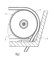
Fig. 2 eine Ansicht in Pfeilrichtung A derFig. 1 , -
Fig. 3 eine Ansicht entsprechendFig. 1 mit einer anderen Ausführungsform der Erfindung, -
Fig. 4 eine Einzelheit X derFig. 1 als Schrägansicht, -
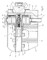
Fig. 5 eine weitere Ausführungsform der Erfindung mit einem zentral angeordneten Ventil, -
Fig. 6 eine Einzelheit Y der Ausführungsform nachFig. 5 . - Von einer Brennkraftmaschine 1 ist eine Nockenwelle 2 dargestellt -
Fig. 1 -, die bspw. zur Betätigung von einem Brennraum der Brennkraftmaschine mit Medium versorgenden Ventilen -nicht dargestellt- eines Ventiltriebs 3 dient. An einem Ende 4 der Nockenwelle 2 ist eine Verstelleinrichtung 5 vorgesehen, mit der die relative Lage der Nockenwelle 2 veränderbar ist. Die Verstelleinrichtung 5 ist hydraulischer Bauart und umfasst einen Rotor 6 und einen Stator 7. Der Rotor 6 ist fest mit der Nockenwelle 2 verbunden, und der Stator 7 ist unter Vermittlung eines Antriebsrads 8 einer Antriebsvorrichtung mechanisch über ein Endlosglied 8' - Kette, Zahnriemen - mit einer nicht abgebildeten Kurbelwelle gekoppelt. Anstelle des Endlosglieds 8' kann auch ein Zahnradgetriebe vorgesehen sein. Zwischen Rotor 6 und Stator 7 sind nicht gezeigte Druckkammern ausgebildet, über die die Verstellung des Rotors 6 bzw. der in einem Zylinderkopf 9 -Fig. 2 - der Brennkraftmaschine 1 angeordneten Nockenwelle 2 bewerkstelligt wird. In den vom Stator 7 umgebenen Rotor 6 eingearbeitet ist eine axiale Bohrung 10, die einen Wellenabschnitt 11 der Nockenwelle 2 umgibt. - Der Rotor 6 ist mit einer über die Breite B der Verstelleinrichtung 5 hinausragenden axialen Verlängerung 12 versehen, die aus einem Stück mit dem Rotor 6 hergestellt ist; denkbar ist aber auch Verlängerung 12 und den Rotor 6 als getrennte Teile darzustellen, die nach ihrer Fertigung zu einer Baueinheit zusammengefasst werden. In der Verlängerung 12 ist die Bohrung 10 fortgeführt, und Verlängerung 12 und Bohrung 10 bilden eine den Wellenabschnitt 11 der Nockenwelle 2 fest umschließende Nabe 13.
- Die von der Nabe 13 umschlossene Nockenwelle 2 umfasst einen Rohrkörper 14, auf dem Nocken 15 und 16 zur Betätigung der Ventile durch Fügen festgesetzt sind, d. h. die Nockenwelle 2 ist von gebauter Gattung - geringeres Gewicht -. Der Rohrkörper 14 und die Nocken 15 und 16 sind unabhängig voneinander produzierte Werkstücke, die dann zu der eigentlichen Nockenwelle zusammengebaut werden. Benachbart der Verstelleinrichtung 5 ist in einen Innenraum 17 des Rohrkörpers 14 ein zapfenartiger Einsatz 18 eingebracht, der sich mit einem Zapfenkopf 19 an einer Stirnseite 20 des Rohrkörpers 14 abstützt. Der Einsatz 18 ist zentrisch hohl gebohrt und nimmt einen Ventilschieber auf - nicht abgebildet -. Der Ventilschieber dient zur Ölversorgung der Verstelleinrichtung 5.
- Zur Lagerung der Nockenwelle 2 sind axial beabstandete Nockenwellenlager, wie das Nockenwellenlager 22, vorgesehen, wovon das sich aus dem Zylinderkopf 21 ausbildende Nockenwellenlager sich benachbart der Nabe 13 erstreckt. Um die Biegesteifigkeit der Nockenwelle 2 zusätzlich zu erhöhen, wirken das Nockenwellenlager am Zylinderkopf 21 und die Nabe 13 steifigkeitserhöhend zusammen. Hierzu ragt die Nabe 13 mit einem freien Ende 23 der Verlängerung 10 in eine Lagerbohrung 24 des Nockenwellenlagers des Zylinderkopfs 21 hinein, anders ausgedrückt, die Nabe 13 rotiert mit einer Außenseite 25 in der Lagerbohrung 24. Ein Innendurchmesser Di und ein Außendurchmesser Da des Rohrkörpers 14 der Nockenwelle 2 sind über die gesamte Länge der besagten Nockenwelle 2 im Wesentlichen konstant.
- Bei einer Nockenwelle 26 -
Fig. 3 -, die mit einer Verstelleinrichtung 27 versehen ist, ist ein Rohrkörper 28 vorgesehen, der in einem Bereich einer Nabe 29 eines Rotors 30 mit einem Außendurchmesser Dak versehen ist, der kleiner ist als ein Außendurchmesser Dag im übrigen Bereich des Rohrkörpers 28. Die Innendurchmesser DiI und DiII sind bei diesem Ausführungsbeispiel entsprechend angepasst. Dabei kann die Wanddicke Wd des Rohrkörpers 28, über die Längserstreckung des Rohrkörpers 28 gesehen, konstant oder aber auch unterschiedlich dimensioniert sein, dergestalt, dass in letzterem Fall die Wanddicke Wd des Rohrkörper 28 - auch die des Rohrkörpers 14 - an die Belastungen der Nockenwelle 26 angepasst ist. Zur Lagerung der Nockenwelle 26 sind mit axialem Abstand NockenwellenLager 31 und 32 vorgesehen. Aufgrund der Durchmesser Konfiguration Dak und Dag des Rohrkörpers 28 sowie DaN der Nabe 29 weisen Lagerbohrungen 33 und 34 einen gleichen Durchmesser auf, was zur Vereinfachung der mechanischen Bearbeitung dieser Lagerbohrungen 31 und 32 beiträgt. - Die Nabe 13 - und auch die Nabe 29 - sind unter Vermittlung von Formschluss mit dem Rohrkörper 14 verbunden. Hierzu dient eine Verzahnung 35 zwischen Nabe 13 und Rohrkörper 14. Es ist aber auch möglich, die Fixierung der Nabe 13 auf dem Rohrkörper 14 mittels Kraftschluss vorzunehmen, wofür sich ein Längspressverband - axiales Zusammenpressen bspw. ohne Erwärmung der Teile -, ein Querpressverband - Aufschrumpfen, und zwar durch Erwärmung der Nabe oder Abkühlung der Welle- oder dgl. eignet. Denkbar ist darüber hinaus die Nabe 13 auf dem Rohrkörper 14 stoffschlüssig, will heißen durch Schweißen, Kleben, Löten oder dgl. zu fixieren. Außerdem eignet sich ferner zur Fixierung der Nabe 13 auf dem Rohrkörper 14 eine Kombination von unterschiedlichen Verbindungskonstruktionen betreffend Form- und Kraftschluss.
- Schließlich werden der Rotor 6 und der Stator 7 in axialer Richtung der Nockenwelle 2, gesehen von Schließplatten 36 und 37, begrenzt, die als vorgefertigte Bauteile ausgeführt sind. Diese Schließplatten 36 und 37 werden unter Vermittlung von Schrauben - nicht gezeigt - an der Verstelleinrichtung 5 in Lage gehalten.
-
Fig. 5 zeigt einen Ausschnitt aus einer Verbrennungskraftmaschine 38. Die Nockenwelle 39 ist Teil des Ventiltriebs 40. An einem der Enden 41 der Nockenwelle 39 ist eine erfindungsgemäße Verstelleinrichtung 42 angeordnet. Die Verstelleinrichtung 42 kann auf der Außenseite der Nockenwelle 39 durch eine geeignete Verbindungstechnik, wie z. B. einen Formschluss über Verzahnungselemente, einen Stoffschluss über Verschweißen oder einen Kraftschluss über einen Pressverband, eine drehmomentübertragende Verbindung herstellen. Die Verstelleinrichtung 42 arbeitet nach einem schwenkmotorartigen Verstellprinzip. Die Verstelleinrichtung 42 kann auch als Flügelzellenversteller bezeichnet werden. Aus diesem Grund hat die Verstelleinrichtung 42 einen Rotor 43 und einen Stator 44. Rotor 43 und Stator 44 sind koaxial angeordnete flache, scheibenartige Bauteile, wobei parallel zum Rotor 43 eine Rückstellfeder 45, insbesondere in Form einer Spiralfeder, angeordnet wird, die den Rotor 43 gegenüber dem Stator 44 in eine Zwangsposition drückt, wenn der hydraulische Druck zwischen Rotor 43 und Stator 44 in den Hydraulikkammern nicht ausreichend hoch ist, um gegen die Federkraft der Rückstellfeder 45 gegensinnig anzuarbeiten. Auf der Außenseite des Stators 44 ist ein Antriebsrad 46, vorzugsweise in den Stator 44 eingeformt. An das Antriebsrad 46 greift ein Endlostrieb 47 an, der, z. B. wie dargestellt, ein Kettentrieb sein kann. Der inFigur 5 dargestellte Ausschnitt der Verbrennungskraftmaschine 38 ist vorrangig der Zylinderkopf 48. Der Rotor 43 ist so gestaltet, dass in der Mitte, dem koaxial zusammenfallenden Zentrum mit dem Stator 44, eine bohrungsartige Nockenwellenaufnahme 49 vorgehalten ist, in die das eine Ende 41 der Nockenwelle 39 eingesetzt werden kann. Über die Verstelleinrichtung 42, über den Endlostrieb 47 und über in den Endlostrieb eingreifende weitere Bauteile ist ein Kettentriebdeckel 50 u. a. als Berührungsschutz darüber gespannt. Der Kettentriebdeckel 50 hat eine Ausnehmung, in die ein Ventil 51 mit dem elektromagnetischen Teil 52 gesteckt werden kann und das über den Ventilflansch 55 an dem Kettentriebdeckel 50 befestigt werden kann. Von der Außenseite her kann der elektromagnetische Teil 52 über den Stecker 53 elektrisch kontaktiert werden. Auf der Innenseite des Kettentriebdeckels steht der Stößel 54 aus dem elektromagnetischen Teil 52 des Ventils 51 hervor. Der Stößel mündet in eine Ventilhülse 56. Die Ventilhülse 56 ist vorzugsweise aus einem besonders festen Metall gefertigt, z. B. aus Stahl. In der Ventilhülse 56 läuft ein Kolben 58 des Ventils 51, der durch eine Kolbenvorspannfeder 57 eine Vorzugsposition, insbesondere im unbestromten Zustand, einnehmen kann. Das Ventil 51 hat unter Inanspruchnahme der Länge der Ventilhülse 56 eine solche Länge, dass ein Wellenabschnitt 59 der als Hohlnockenwelle gestalteten Nockenwelle 39 innwandig durch das Ventil 51 unterstützt wird. Ungefähr der gleiche Wellenabschnitt wird auf der Außenseite der Nockenwelle 39 durch die axiale Verlängerung 60 des Rotors 43 nachgeformt. Wie inFigur 6 deutlicher dargestellt, kann die axiale Verlängerung 60 nachFigur 5 mit Ölführungskanälen 61 durchsetzt sein, die die Ölversorgung für die Verstelleinrichtung 42 sicherstellen. Gleichzeitig kann ein solcher Ölführungskanal 61 so gestaltet sein, dass Öl zur Lagerschmierung des Nockenwellenlagers 68 der ihn durchsetzenden Nabe 62 (Figur 6 ) genutzt werden kann. Wie weiterhin inFigur 5 zu sehen ist, ist die Nockenwelle 39 in ihrer zentralen Welle als Rohrkörper 63 ausgeführt. An ausgewählten Stellen des Rohrkörpers 63 befinden sich, insbesondere durch Aufweiten des Rohrkörpers 63, befestigte Nocken 64, 65. Zwischen den einzelnen Nocken 64, 65 können weitere Nockenwellenlager 69 vorgesehen sein. Die Nabe 62 (Fig. 6 ) der Verstelleinrichtung 42 reicht wenigstens bis zum ersten Nockenwellenlager 68, vorzugsweise durch das Nockenwellenlager 68, hindurch. Die als Ventilhülse 56 zur Führung des Kolbens 58 gestaltete Verlängerung, die zapfenartig ist, ist in einem Endbereich so aufgeweitet, dass die Ventilhülse 56 an einer Stirnseite 67 des Rohrkörpers 63 der Nockenwelle 39 in arretierender Weise zum Anschlag kommt. Weil die Nockenwelle 39 eine Hohlnockenwelle ist, bietet die Nockenwelle 39 einen Innenraum 66, der teilweise durch die hydraulischen Teile des Ventils 51 im Endbereich der Nockenwelle 39 ausgefüllt ist. Auf beiden axialen Seiten der Verstelleinrichtung 42 sind Stirnplatten 70, 71 zum hydraulischen Verschließen der Hydraulikkammern zwischen Stator 44 und Rotor 43 angeordnet. Die Stirnplatten 70, 71 können Senkvertiefungen 72, 73 versehen sein, in denen die die beiden Stirnplatten 70, 71 verspannenden Senkkopfschrauben platzsparend liegen können. Der hydraulische Teil des Ventils 51 ist mehrteilig mit dem zentral angeordneten Kolben 58 aufgebaut. Der Kolben 58, so wie deutlicher inFigur 6 zu sehen ist, wird durch die Kolbenvorspannfeder 57 in einer ausgewählten Ruhestellung gehalten. Der Kolben 58, so wie inFigur 5 zu sehen ist, wird durch die Ventilhülse 56 eingefasst. Als weiteres Bauteil zur axialen Ausrichtung und Orientierung des Kolbens 58 ist eine - inFigur 6 dargestellte - Führungshülse 74 im Übergangsbereich vom elektromagnetischen Teil zum hydraulischen Teil des Ventils 51 vorgesehen. Weitere Lagerschmierungen 84 können für die weiteren Nockenwellenlager 69 durch Ölführungen im Zylinderkopf 48 vorgesehen sein. Die Nockenwelle 39 ist von gebauter Art und Weise. Die Nockenwelle 39 ist so dünnwandig ausgelegt, insbesondere zur Förderung der Herstellbarkeit der gebauten Nockenwelle, dass das eingeleitete Drehmoment über die hohlzylindrische Nockenwelle nicht übertragbar wäre. - Weitere Einzelheiten des Bereichs Y der
Figur 5 können in derFigur 6 näher betrachtet werden. Der Rohrkörper 63 hat einen Innenraum 66. Der Innenraum 66 ist teilweise ausgefüllt. Zum Ausfüllen dient die Ventilhülse 56. Die Ventilhülse 56 bietet gleichzeitig einen Anlage- bzw. Sitzraum für die Kolbenvorspannfeder 57. Auf ungefähr gleicher Höhe entlang des Rohrkörpers 63 wie sich der Rotor 43 mit seiner axialen Verlängerung 60 befindet, ist der Kolben 58 in der Ventilhülse 56 angeordnet. Die Ventilhülse 56 stützt sich im Bereich eines Ventilhülsenanschlags 75 an dem Rohrkörper 63 stirnseitig ab. Die Ventilhülse 56 ist nicht massiv ausgestaltet. Neben den Hohlräumen für solche Bauteile, wie Kolben 58 und Kolbenvorspannfeder 57, bietet die Ventilhülse 56 Hülsenhydraulikmittelführungen 76, 77 für die Zu- und Ableitung des Hydraulikmittels, wie Öl, zu der Verstelleinrichtung 42 (sieheFigur 5 ). Zwischen Ventilhülse 56 und Kolben 58 sind Hohlräume und Absperrbereiche durch Stege 78, 79 und entsprechende Kolbennuten 81, 82 realisiert. Durch entsprechende Überdeckungen, Ablaufkantensteuerungen und Ansteuerkanten kann das hydraulische Verhalten in Abhängigkeit der Stößelstellung des Stößels 54 aufgrund der elektrischen Bestromung des elektromagnetischen Teils 52 beeinflusst werden. Der Kolben 58 hat einen Kolbenzentralkanal 80, der als P-Kanal oder auch als T-Kanal innerhalb der Hohlnockenwelle 39 dienen kann. Auf der Außenseite der Rückstellfeder 45 kann ein Statordeckel 83 angeordnet werden, der bündig mit dem Ventilhülsenanschlag 75 bis zum Außendurchmesser des Rohrkörpers 63 herangeführt sein kann. Die Nabe 62 verläuft bis zu einem Nockenwellenlager parallel zum Rohrkörper 63 in Form einer axialen Verlängerung 60. Somit kann ein gewisses Drehmoment über die axiale Verlängerung in das Nockenwellenlager eingeleitet werden. Der Rohrkörper 63 der Nockenwelle 39 wird ergänzend und zusätzlich durch das Ventil 51 gestützt. Das Ventil 51 ist durch die Ventilhülse 56 entlang des Endbereichs des Rohrkörpers 63 bis wenigstens zum ersten Lager verstärkt. Aus Materialersparnisgründen kann die Ventilhülse 56, wie inFigur 6 dargestellt, teilweise hohl ausgeführt sein, denn wesentlich sind die äußeren, zylindrisch zu schaffenden Stützwände für den Rohrkörper 63. Die Ventilhülse 56 ist, abgesehen von den Ausnehmungen, wie die Hülsenhydraulikmittelführung 76 bzw. 77 ein äußerlich gesehenes massives Teil, das zur Mitte hin verschiedene Ausnehmungen, z. B. für den Kolben 58 aufweisen kann. - Obwohl die Nockenwelle 39 eigentlich zu dünnwandig für Drehmomente, die mit Werten von 500 N bis 3.000 N über die Kette eingeleitet werden, ausgelegt ist, kann die über den Hebelarm von ca. 40 mm erzeugte Belastung auf das ca. 20 mm im Durchmesser große Lager unter Zuhilfenahme der axialen Verlängerung und der innen unterstützenden Ventilhülse geschickt bis in die Nockenwellenlager geführt werden. Wie in den dargestellten Schnittansichten zu sehen ist, wird die Nockenwelle inn- und/oder außenwandig eingefasst und achsparallel verstärkt. Die rohr- oder hülsenförmige, hohle Nockenwelle schafft so durch das Ventil oder durch den Rotor oder durch Rotor und Ventil, insbesondere Ventilhülse, zusammen einen mehrschichtigen, annulus- bzw. kreisringausfüllenden Nockenwellenendbereich. Es werden einzelne übereinander, sich gegenseitig verstärkende Lagen gebildet, die insgesamt einen so dicken Nockenwellenendbereich schaffen, dass über das Ende bis in eines der ersten Nockenwellenlager ein hohes, für die Nockenwelle alleine zu großes Drehmoment übertragbar ist. Eine erfindungsgemäße Brennkraftmaschine kommt ohne zusätzliche, am Zylinderkopf anzuordnende Stützbrille aus. Die bisher übliche seitliche Verlängerung des ersten Nockenwellenlagers durch eine zusätzliche Brille zur Abstützung kann somit entfallen. Die axiale Verlängerung des Rotors sorgt folglich für weitere Materialersparnis. Die Ventilhülse kann aus Stahl gefertigt sein. Weniger günstig wäre eine Ventilhülse aus Aluminium. Die Ventilhülse ist so bemessen, dass der innen laufende Kolben leichtgängig von dem Stößel angetrieben werden kann.
Bezugszeichenliste: Bezugszeichen Bedeutung Graphische Darstellung 1 Brennkraftmaschine Fig. 1 2 Nockenwelle Fig. 1 3 Ventiltrieb Fig. 1 4 Ende der Nockenwelle Fig. 1 5 Verstelleinrichtung Fig. 1 ,Fig. 2 6 Rotor Fig. 1 ,Fig. 4 7 Stator Fig. 1 8 Antriebsrad Fig. 1 ,Fig. 2 8' Endlosglied wie Kette oder Zahnriemen Fig. 1 ,Fig. 2 9 Zylinderkopf Fig. 1 ,Fig. 2 10 Bohrung Fig. 1 11 Wellenabschnitt Fig. 1 12 Axiale Verlängerung Fig. 1 13 Nabe Fig. 1 ,Fig. 4 14 Rohrkörper Fig. 1 15 Nocken Fig. 1 16 Nocken Fig. 1 17 Innenraum Fig. 1 18 Zapfenartiger Einsatz Fig. 1 19 Zapfenkopf Fig. 1 20 Stirnseite des Rohrkörpers 14 Fig. 1 21 Lagernder Teil des Zylinderkopf Fig. 1 22 Nockenwellenlager Fig. 1 23 Freies Ende Fig. 1 24 Lagerbohrung Fig. 1 25 Außenseite Fig. 1 26 Nockenwelle Fig. 3 27 Verstelleinrichtung Fig. 3 28 Rohrkörper Fig. 3 29 Nabe Fig. 3 30 Rotor Fig. 3 31 Nockenwellenlager Fig. 1 ,Fig. 3 32 Nockenwellenlager Fig. 1 ,Fig. 3 33 Lagerbohrung Fig. 3 34 Lagerbohrung Fig. 3 35 Verzahnung Fig. 4 36 Schließplatte Fig. 1 37 Schließplatte Fig. 1 38 Verbrennungskraftmaschine Fig. 5 39 Nockenwelle Fig. 5 40 Ventiltrieb Fig. 5 41 Ende der Nockenwelle Fig. 5 42 Verstelleinrichtung Fig. 5 43 Rotor Fig. 5 ,Fig. 6 44 Stator Fig. 5 45 Rückstellfeder Fig. 5 ,Fig. 6 46 Antriebsrad Fig. 5 47 Endlostrieb, insbesondere als Kettentrieb Fig. 5 48 Zylinderkopf Fig. 5 49 bohrungsartige Nockenwellenaufnahme Fig. 5 50 Kettentriebdeckel Fig. 5 51 Ventil Fig. 5 52 Elektromagnetischer Teil Fig. 5 ,Fig. 6 53 Stecker Fig. 5 54 Stößel Fig. 5 ,Fig. 6 55 Ventilflansch Fig. 5 56 Ventilhülse Fig. 5 ,Fig. 6 57 Kolbenvorspannfeder Fig. 5 ,Fig. 6 58 Kolben Fig. 5 ,Fig. 6 59 Wellenabschnitt Fig. 5 60 Axiale Verlängerung Fig. 5 ,Fig. 6 61 Ölführungskanal Fig. 6 62 Nabe Fig. 6 63 Rohrkörper Fig. 5 ,Fig. 6 64 Nocken Fig. 5 65 Nocken Fig. 5 66 Innenraum Fig. 5 ,Fig. 6 67 Stirnseite des Rohrkörpers 63 Fig. 5 68 Nockenwellenlager Fig. 5 69 Nockenwellenlager Fig. 5 70 Erste Stirnplatte Fig. 5 71 Zweite Stirnplatte Fig. 5 72 Senkvertiefung Fig. 5 73 Senkvertiefung Fig. 5 74 Führungshülse Fig. 6 75 Ventilhülsenanschlag Fig. 6 76 Hülsenhydraulikmittelführung Fig. 6 77 Hülsenhydraulikmittelführung Fig. 6 78 Steg Fig. 6 79 Steg Fig. 6 80 Kolbenzentralkanal Fig. 6 81 Kolbennut Fig. 6 82 Kolbennut Fig. 6 83 Statordeckel Fig. 6 84 Lagerschmierung Fig. 5 Da Außendurchmesser Fig. 1 Dak Außendurchmesser Fig. 3 Dag Außendurchmesser Fig. 3 Di Innendurchmesser Fig. 1 DiI Innendurchmesser Fig. 3 DiII Innendurchmesser Fig. 3 Wd Wanddicke Fig. 3 DaN Durchmesser der Nabe Fig. 3 A Pfeilrichtung Fig. 1 B Breite der Verstelleinrichtung 5 Fig. 1 X Einzelheit Fig. 1 Y Einzelheit Fig. 5 ,Fig. 6
Claims (11)
- Verstelleinrichtung (5, 27) für eine Brennkraftmaschine (1),
mit der die relative Lage einer Nockenwelle (2, 26) zur Beeinflussung von Steuerzeiten von Ventilen eines Ventiltriebs (3) der Brennkraftmaschine (1) zu verändern ist,
welche Verstelleinrichtung (5, 27) einen fest mit der Nockenwelle (2, 26) zu verbindenden Rotor (6, 30) und einen mit einer Antriebsvorrichtung zu koppelnden Stator (7) umfasst,
wobei eine axiale Bohrung (10) des Rotors (6) zur Aufnahme eines Wellenabschnitts (11) der Nockenwelle (2, 26) bestimmt ist und
wobei die axiale Bohrung (10) des vom Stator (7) umgebenen Rotors (6, 30) in wenigstens einer über die Breite der Verstelleinrichtung (5, 27) hinausgehenden axialen Verlängerung (12) fortgeführt ist,
wobei der Rotor (6, 30) und die Verlängerung (12) eine die Nockenwelle (2, 26) fest umschließende Nabe (13, 29) bilden, die als ein fester Verbund ausgeführt sind, und wobei die Nockenwelle (2, 26) einen Innenraum (66) aufweist, dadurch gekennzeichnet, dass der Innenraum (66) an dem dem Rotor (6, 30) benachbarten Ende teilweise für Hydraulikmittelführungen (76, 77) mit einem Bauteil, wie einem zapfenartigen Einsatz (18) oder einer Ventilhülse (56), ausgefüllt ist,
für die Zu- und Ableitung eines Hydraulikmittels zu der Verstelleinrichtung (5, 27) dient,
und dass die Nockenwelle (2, 26) eine zu geringe Biegesteifigkeit im Vergleich zu einem von außen auf die Verstelleinrichtung (5, 27) eingeleiteten Biegemoment aufweist,
was dadurch kompensiert ist,
dass die axiale Verlängerung (12) in der Art fortgeführt ist,
dass der feste Verbund der Art ausgeführt ist,
dass ein Nockenwellenlager (21, 31, 32) mit der Nabe (13, 29) eine die Biegesteifigkeit der Nockenwelle (2, 26) erhöhende Längsverstärkung bildet,
und was dadurch kompensiert ist,
dass das Bauteil im Innenraum (66) der Nockenwelle (2, 26) ein einfassendes Bauteil ist, das parallel verlaufend zur Nockenwelle (2, 26) ist und zusätzlich die Nockenwelle (2, 26) stärkt. - Verstelleinrichtung nach Anspruch 1, dadurch gekennzeichnet, dass die von der Nabe (13, 29) zu umschließende Nockenwelle (2, 26) einen Rohrkörper (14, 28) umfasst.
- Verstelleinrichtung nach einem der Ansprüche 1 bis 2, dadurch gekennzeichnet, dass ein Nockenwellenlager (21, 31) für die Nockenwelle (2, 26) sich radial benachbart der Nabe (13, 29) erstreckt, wobei das Nockenwellenlager (21, 31) und die Nabe (13, 29) zur Erhöhung der Biegesteifigkeit der Nockenwelle (2, 26) zusammenarbeiten.
- Verstelleinrichtung nach Anspruch 3, dadurch gekennzeichnet, dass die Nabe (13, 29) in eine Lagerbohrung (24) des Nockenwellenlagers (21, 31) hineinragt.
- Verstelleinrichtung nach einem der Ansprüche 2 bis 4, dadurch gekennzeichnet, dass auf einem dem Rotor (6) benachbarten Ende des Rohrkörpers (14) ein zapfenartiger Einsatz (18) in einem Innenraum (17) des besagten Rohrkörpers (14) vorgesehen ist.
- Verstelleinrichtung nach einem oder mehreren der vorangehenden Ansprüche, dadurch gekennzeichnet, dass
der Rotor und der Stator in axialer Richtung der Nockenwelle (2, 16) gesehen von Schließplatten (36 und 37) begrenzt werden, die insbesondere vorgefertigte Bauteile sind. - Verstelleinrichtung nach einem der Ansprüche 2 bis 6, dadurch gekennzeichnet, dass der Innendurchmesser (Di) und der Außendurchmesser (Da) des Rohrkörpers (14), über die axiale Länge des besagten Rohrkörpers (14) gesehen, im Wesentlichen konstant sind.
- Verstelleinrichtung nach einem der Ansprüche 2 bis 6, dadurch gekennzeichnet, dass zumindest der Innendurchmesser (Di) des Rohrkörpers (28), über die axiale Länge des besagten Rohrkörpers (28) gesehen, an die auftretenden Belastungen der Nockenwelle (26) entlang der Erstreckung des Rohrkörpers angepasst ist.
- Verstelleinrichtung nach einem der vorhergehenden Ansprüche, dadurch gekennzeichnet, dass
in die aufzunehmende Nockenwelle (39) ein cartridgeartiges Steuerventil (51) innwandig verstärkend bis zu einem Nockenwellenlager (31, 68) reichend eingesetzt ist, wobei eine Hülse (56) des Steuerventils (51) die vom Rotor (6, 43) eingeleitete Drehmomentenübertragung unterstützt. - Brennkraftmaschine (1, 38) mit zumindest einer Verstelleinrichtung (5, 42) nach einem der vorhergehenden Ansprüche und einer rohrförmigen Hohlnockenwelle (2, 26, 39), auf der die schwenkmotorartige Verstelleinrichtung (5, 42), die einen Rotor (6, 43) und einen Stator (7, 44) umfasst, endlings (41) angeordnet so sitzt, dass ein Fortsatz (29) des Rotors (6, 43) aus der Verstelleinrichtung (5, 42) hinausragend bis zu einem Nockenwellenlager (31, 68) reicht,
dadurch gekennzeichnet, dass
die Hohlnockenwelle (2, 26, 39) für das über die Verstelleinrichtung (5, 42) eingeleitete Drehmoment unterdimensioniert ist, jedoch die Hohlnockenwelle (2, 26, 39) durch zumindest ein die Hohlnockenwelle (2, 26, 39) flankierendes Bauteil wie ein Ventil (51) oder der Rotor (6, 43) für das maximal zu erwartende Drehmoment ausgelegt ist. - Brennkraftmaschine (1, 38) nach Anspruch 10, dadurch gekennzeichnet, dass das Ventil (51) einen eine Ventilhülse (56) umfassenden Hydraulikteil (56, 58) hat, der bis zu einer Innenwand der Hohlnockenwelle (2, 26, 39) reicht.
Priority Applications (1)
| Application Number | Priority Date | Filing Date | Title |
|---|---|---|---|
| EP20080101750 EP2093388B1 (de) | 2008-02-19 | 2008-02-19 | Verstelleinrichtung für eine Brennkraftmaschine |
Applications Claiming Priority (1)
| Application Number | Priority Date | Filing Date | Title |
|---|---|---|---|
| EP20080101750 EP2093388B1 (de) | 2008-02-19 | 2008-02-19 | Verstelleinrichtung für eine Brennkraftmaschine |
Publications (2)
| Publication Number | Publication Date |
|---|---|
| EP2093388A1 EP2093388A1 (de) | 2009-08-26 |
| EP2093388B1 true EP2093388B1 (de) | 2014-10-08 |
Family
ID=39596465
Family Applications (1)
| Application Number | Title | Priority Date | Filing Date |
|---|---|---|---|
| EP20080101750 Not-in-force EP2093388B1 (de) | 2008-02-19 | 2008-02-19 | Verstelleinrichtung für eine Brennkraftmaschine |
Country Status (1)
| Country | Link |
|---|---|
| EP (1) | EP2093388B1 (de) |
Families Citing this family (6)
| Publication number | Priority date | Publication date | Assignee | Title |
|---|---|---|---|---|
| DE102009050779B4 (de) | 2009-10-27 | 2016-05-04 | Hilite Germany Gmbh | Schwenkmotornockenwellenversteller mit einer Reibscheibe und Montageverfahren |
| DE102009052841A1 (de) * | 2009-11-13 | 2011-05-19 | Hydraulik-Ring Gmbh | Nockenwelleneinsatz |
| DE102010045358A1 (de) | 2010-04-10 | 2011-10-13 | Hydraulik-Ring Gmbh | Schwenkmotornockenwellenversteller mit einem Hydraulikventil |
| DE102010019005B4 (de) | 2010-05-03 | 2017-03-23 | Hilite Germany Gmbh | Schwenkmotorversteller |
| DE102010061337B4 (de) | 2010-12-20 | 2015-07-09 | Hilite Germany Gmbh | Hydraulikventil für einen Schwenkmotorversteller |
| DE102015206699A1 (de) * | 2015-04-15 | 2016-03-24 | Schaeffler Technologies AG & Co. KG | Nockenwellenversteller mit Hydraulikmittelleitkanälen in /an drehmomentübertragenden Formschlusselementen |
Family Cites Families (6)
| Publication number | Priority date | Publication date | Assignee | Title |
|---|---|---|---|---|
| JP3991473B2 (ja) * | 1998-10-05 | 2007-10-17 | アイシン精機株式会社 | 弁開閉時期制御装置 |
| US6799544B1 (en) * | 2003-05-29 | 2004-10-05 | Delphi Technologies, Inc. | Method and apparatus for actuating a cam phaser |
| US6814037B1 (en) * | 2003-06-24 | 2004-11-09 | Borgwarner Inc. | Variable camshaft timing for internal combustion engine with actuator locking |
| DE10346444A1 (de) * | 2003-10-07 | 2005-06-09 | Daimlerchrysler Ag | Nockenwellenversteller für eine Brennkraftmaschine mit Hydraulikmittelführungen |
| GB2423565A (en) * | 2005-02-23 | 2006-08-30 | Mechadyne Plc | Inner camshaft of SCP assembly receives drive via sleeve on outer tube |
| US7228831B1 (en) * | 2005-12-14 | 2007-06-12 | Ford Global Technologies, Llc | Camshaft and oil-controlled camshaft phaser for automotive engine |
-
2008
- 2008-02-19 EP EP20080101750 patent/EP2093388B1/de not_active Not-in-force
Also Published As
| Publication number | Publication date |
|---|---|
| EP2093388A1 (de) | 2009-08-26 |
Similar Documents
| Publication | Publication Date | Title |
|---|---|---|
| EP1860286B1 (de) | Nockenwelle | |
| EP0335083B1 (de) | Vorrichtung zur relativen Winkelverstellung zwischen zwei in Antriebsverbindung stehenden Wellen | |
| EP0469332B1 (de) | Vorrichtung zur Änderung der Ventilsteuerzeiten einer Brennkraftmaschine | |
| DE4218078C5 (de) | Vorrichtung zur selbsttätigen, kontinuierlichen Winkelverstellung zwischen zwei in Antriebsverbindung stehenden Wellen | |
| DE10084408B4 (de) | Vorrichtung zum Verändern der Steuerzeiten von Gaswechselventilen einer Brennkraftmaschine | |
| DE102011076652B4 (de) | Vorrichtung zur Verstellung der relativen Drehwinkelposition geschachtelter Nockenwellen | |
| EP2286067B1 (de) | Verstellbare nockenwellenanordnung | |
| EP2093388B1 (de) | Verstelleinrichtung für eine Brennkraftmaschine | |
| EP2415979B1 (de) | Nockenwellenversteller | |
| DE102010019005A1 (de) | Hydraulikventil | |
| WO1992002739A1 (de) | Verbindung eines auf fertigmass gefertigten zylinderkörpers | |
| EP2486248A1 (de) | Nockenwellenanordnung | |
| DE10346448A1 (de) | Nockenwellenversteller für eine Brennkraftmaschine | |
| DE102004026863A1 (de) | Nockenwellerversteller | |
| WO2008009548A1 (de) | Gruppe mehrerer nockenwellen mit nockenwellenverstellern | |
| DE19908146B4 (de) | Vorrichtung zum Verändern der Steuerzeiten von Gaswechselventilen einer Brennkraftmaschine | |
| DE202010006605U1 (de) | Zentralventil | |
| DE102006039371A1 (de) | Verstelleinrichtung für eine Brennkraftmaschine | |
| DE102007019920A1 (de) | Verrieglungs- und Drehwinkelbegrenzungsanordnung eines Nockenwellenverstellers | |
| DE102006007651A1 (de) | Nockenwellenversteller mit einem Überlagerungsgetriebe | |
| DE102011077020A1 (de) | Differenzgewindespindel zur Befestigung von Nockenwellenverstellern | |
| DE102007035672B4 (de) | Nockenwellenversteller | |
| DE10346447B4 (de) | Verfahren zur Befestigung eines Nockenwellenverstellers an einer Nockenwelle einer Brennkraftmaschine | |
| DE19850947A1 (de) | Vorrichtung zur Steuerung der Öffnungs- und Schließzeiten von Gaswechselventilen einer Brennkraftmaschine | |
| DE102010013777A1 (de) | Zentralventil |
Legal Events
| Date | Code | Title | Description |
|---|---|---|---|
| PUAI | Public reference made under article 153(3) epc to a published international application that has entered the european phase |
Free format text: ORIGINAL CODE: 0009012 |
|
| 17P | Request for examination filed |
Effective date: 20081004 |
|
| AK | Designated contracting states |
Kind code of ref document: A1 Designated state(s): AT BE BG CH CY CZ DE DK EE ES FI FR GB GR HR HU IE IS IT LI LT LU LV MC MT NL NO PL PT RO SE SI SK TR |
|
| AX | Request for extension of the european patent |
Extension state: AL BA MK RS |
|
| 17Q | First examination report despatched |
Effective date: 20091103 |
|
| AKX | Designation fees paid |
Designated state(s): AT BE BG CH CY CZ DE DK EE ES FI FR GB GR HR HU IE IS IT LI LT LU LV MC MT NL NO PL PT RO SE SI SK TR |
|
| RAP1 | Party data changed (applicant data changed or rights of an application transferred) |
Owner name: HOFER MECHATRONIK GMBH |
|
| GRAP | Despatch of communication of intention to grant a patent |
Free format text: ORIGINAL CODE: EPIDOSNIGR1 |
|
| INTG | Intention to grant announced |
Effective date: 20140522 |
|
| GRAS | Grant fee paid |
Free format text: ORIGINAL CODE: EPIDOSNIGR3 |
|
| GRAA | (expected) grant |
Free format text: ORIGINAL CODE: 0009210 |
|
| AK | Designated contracting states |
Kind code of ref document: B1 Designated state(s): AT BE BG CH CY CZ DE DK EE ES FI FR GB GR HR HU IE IS IT LI LT LU LV MC MT NL NO PL PT RO SE SI SK TR |
|
| REG | Reference to a national code |
Ref country code: GB Ref legal event code: FG4D Free format text: NOT ENGLISH |
|
| REG | Reference to a national code |
Ref country code: AT Ref legal event code: REF Ref document number: 690758 Country of ref document: AT Kind code of ref document: T Effective date: 20141015 Ref country code: CH Ref legal event code: EP |
|
| REG | Reference to a national code |
Ref country code: IE Ref legal event code: FG4D Free format text: LANGUAGE OF EP DOCUMENT: GERMAN |
|
| REG | Reference to a national code |
Ref country code: DE Ref legal event code: R096 Ref document number: 502008012292 Country of ref document: DE Effective date: 20141113 |
|
| REG | Reference to a national code |
Ref country code: NL Ref legal event code: VDEP Effective date: 20141008 |
|
| REG | Reference to a national code |
Ref country code: LT Ref legal event code: MG4D |
|
| PG25 | Lapsed in a contracting state [announced via postgrant information from national office to epo] |
Ref country code: NL Free format text: LAPSE BECAUSE OF FAILURE TO SUBMIT A TRANSLATION OF THE DESCRIPTION OR TO PAY THE FEE WITHIN THE PRESCRIBED TIME-LIMIT Effective date: 20141008 |
|
| PG25 | Lapsed in a contracting state [announced via postgrant information from national office to epo] |
Ref country code: NO Free format text: LAPSE BECAUSE OF FAILURE TO SUBMIT A TRANSLATION OF THE DESCRIPTION OR TO PAY THE FEE WITHIN THE PRESCRIBED TIME-LIMIT Effective date: 20150108 Ref country code: IS Free format text: LAPSE BECAUSE OF FAILURE TO SUBMIT A TRANSLATION OF THE DESCRIPTION OR TO PAY THE FEE WITHIN THE PRESCRIBED TIME-LIMIT Effective date: 20150208 Ref country code: LT Free format text: LAPSE BECAUSE OF FAILURE TO SUBMIT A TRANSLATION OF THE DESCRIPTION OR TO PAY THE FEE WITHIN THE PRESCRIBED TIME-LIMIT Effective date: 20141008 Ref country code: ES Free format text: LAPSE BECAUSE OF FAILURE TO SUBMIT A TRANSLATION OF THE DESCRIPTION OR TO PAY THE FEE WITHIN THE PRESCRIBED TIME-LIMIT Effective date: 20141008 Ref country code: PT Free format text: LAPSE BECAUSE OF FAILURE TO SUBMIT A TRANSLATION OF THE DESCRIPTION OR TO PAY THE FEE WITHIN THE PRESCRIBED TIME-LIMIT Effective date: 20150209 Ref country code: FI Free format text: LAPSE BECAUSE OF FAILURE TO SUBMIT A TRANSLATION OF THE DESCRIPTION OR TO PAY THE FEE WITHIN THE PRESCRIBED TIME-LIMIT Effective date: 20141008 |
|
| PG25 | Lapsed in a contracting state [announced via postgrant information from national office to epo] |
Ref country code: LV Free format text: LAPSE BECAUSE OF FAILURE TO SUBMIT A TRANSLATION OF THE DESCRIPTION OR TO PAY THE FEE WITHIN THE PRESCRIBED TIME-LIMIT Effective date: 20141008 Ref country code: GR Free format text: LAPSE BECAUSE OF FAILURE TO SUBMIT A TRANSLATION OF THE DESCRIPTION OR TO PAY THE FEE WITHIN THE PRESCRIBED TIME-LIMIT Effective date: 20150109 Ref country code: CY Free format text: LAPSE BECAUSE OF FAILURE TO SUBMIT A TRANSLATION OF THE DESCRIPTION OR TO PAY THE FEE WITHIN THE PRESCRIBED TIME-LIMIT Effective date: 20141008 Ref country code: SE Free format text: LAPSE BECAUSE OF FAILURE TO SUBMIT A TRANSLATION OF THE DESCRIPTION OR TO PAY THE FEE WITHIN THE PRESCRIBED TIME-LIMIT Effective date: 20141008 Ref country code: HR Free format text: LAPSE BECAUSE OF FAILURE TO SUBMIT A TRANSLATION OF THE DESCRIPTION OR TO PAY THE FEE WITHIN THE PRESCRIBED TIME-LIMIT Effective date: 20141008 Ref country code: PL Free format text: LAPSE BECAUSE OF FAILURE TO SUBMIT A TRANSLATION OF THE DESCRIPTION OR TO PAY THE FEE WITHIN THE PRESCRIBED TIME-LIMIT Effective date: 20141008 |
|
| PG25 | Lapsed in a contracting state [announced via postgrant information from national office to epo] |
Ref country code: BE Free format text: LAPSE BECAUSE OF NON-PAYMENT OF DUE FEES Effective date: 20150228 |
|
| REG | Reference to a national code |
Ref country code: DE Ref legal event code: R097 Ref document number: 502008012292 Country of ref document: DE |
|
| PG25 | Lapsed in a contracting state [announced via postgrant information from national office to epo] |
Ref country code: SK Free format text: LAPSE BECAUSE OF FAILURE TO SUBMIT A TRANSLATION OF THE DESCRIPTION OR TO PAY THE FEE WITHIN THE PRESCRIBED TIME-LIMIT Effective date: 20141008 Ref country code: RO Free format text: LAPSE BECAUSE OF FAILURE TO SUBMIT A TRANSLATION OF THE DESCRIPTION OR TO PAY THE FEE WITHIN THE PRESCRIBED TIME-LIMIT Effective date: 20141008 Ref country code: EE Free format text: LAPSE BECAUSE OF FAILURE TO SUBMIT A TRANSLATION OF THE DESCRIPTION OR TO PAY THE FEE WITHIN THE PRESCRIBED TIME-LIMIT Effective date: 20141008 Ref country code: DK Free format text: LAPSE BECAUSE OF FAILURE TO SUBMIT A TRANSLATION OF THE DESCRIPTION OR TO PAY THE FEE WITHIN THE PRESCRIBED TIME-LIMIT Effective date: 20141008 Ref country code: CZ Free format text: LAPSE BECAUSE OF FAILURE TO SUBMIT A TRANSLATION OF THE DESCRIPTION OR TO PAY THE FEE WITHIN THE PRESCRIBED TIME-LIMIT Effective date: 20141008 |
|
| PLBE | No opposition filed within time limit |
Free format text: ORIGINAL CODE: 0009261 |
|
| STAA | Information on the status of an ep patent application or granted ep patent |
Free format text: STATUS: NO OPPOSITION FILED WITHIN TIME LIMIT |
|
| PG25 | Lapsed in a contracting state [announced via postgrant information from national office to epo] |
Ref country code: IT Free format text: LAPSE BECAUSE OF FAILURE TO SUBMIT A TRANSLATION OF THE DESCRIPTION OR TO PAY THE FEE WITHIN THE PRESCRIBED TIME-LIMIT Effective date: 20141008 |
|
| 26N | No opposition filed |
Effective date: 20150709 |
|
| PG25 | Lapsed in a contracting state [announced via postgrant information from national office to epo] |
Ref country code: LU Free format text: LAPSE BECAUSE OF FAILURE TO SUBMIT A TRANSLATION OF THE DESCRIPTION OR TO PAY THE FEE WITHIN THE PRESCRIBED TIME-LIMIT Effective date: 20150219 |
|
| REG | Reference to a national code |
Ref country code: CH Ref legal event code: PL |
|
| GBPC | Gb: european patent ceased through non-payment of renewal fee |
Effective date: 20150219 |
|
| PG25 | Lapsed in a contracting state [announced via postgrant information from national office to epo] |
Ref country code: LI Free format text: LAPSE BECAUSE OF NON-PAYMENT OF DUE FEES Effective date: 20150228 Ref country code: CH Free format text: LAPSE BECAUSE OF NON-PAYMENT OF DUE FEES Effective date: 20150228 Ref country code: MC Free format text: LAPSE BECAUSE OF FAILURE TO SUBMIT A TRANSLATION OF THE DESCRIPTION OR TO PAY THE FEE WITHIN THE PRESCRIBED TIME-LIMIT Effective date: 20141008 |
|
| REG | Reference to a national code |
Ref country code: IE Ref legal event code: MM4A |
|
| REG | Reference to a national code |
Ref country code: FR Ref legal event code: ST Effective date: 20151030 |
|
| PG25 | Lapsed in a contracting state [announced via postgrant information from national office to epo] |
Ref country code: IE Free format text: LAPSE BECAUSE OF NON-PAYMENT OF DUE FEES Effective date: 20150219 Ref country code: GB Free format text: LAPSE BECAUSE OF NON-PAYMENT OF DUE FEES Effective date: 20150219 |
|
| PG25 | Lapsed in a contracting state [announced via postgrant information from national office to epo] |
Ref country code: FR Free format text: LAPSE BECAUSE OF NON-PAYMENT OF DUE FEES Effective date: 20150302 Ref country code: SI Free format text: LAPSE BECAUSE OF FAILURE TO SUBMIT A TRANSLATION OF THE DESCRIPTION OR TO PAY THE FEE WITHIN THE PRESCRIBED TIME-LIMIT Effective date: 20141008 |
|
| REG | Reference to a national code |
Ref country code: AT Ref legal event code: MM01 Ref document number: 690758 Country of ref document: AT Kind code of ref document: T Effective date: 20150219 |
|
| PG25 | Lapsed in a contracting state [announced via postgrant information from national office to epo] |
Ref country code: AT Free format text: LAPSE BECAUSE OF NON-PAYMENT OF DUE FEES Effective date: 20150219 |
|
| PG25 | Lapsed in a contracting state [announced via postgrant information from national office to epo] |
Ref country code: MT Free format text: LAPSE BECAUSE OF FAILURE TO SUBMIT A TRANSLATION OF THE DESCRIPTION OR TO PAY THE FEE WITHIN THE PRESCRIBED TIME-LIMIT Effective date: 20141008 |
|
| PG25 | Lapsed in a contracting state [announced via postgrant information from national office to epo] |
Ref country code: BG Free format text: LAPSE BECAUSE OF FAILURE TO SUBMIT A TRANSLATION OF THE DESCRIPTION OR TO PAY THE FEE WITHIN THE PRESCRIBED TIME-LIMIT Effective date: 20141008 Ref country code: HU Free format text: LAPSE BECAUSE OF FAILURE TO SUBMIT A TRANSLATION OF THE DESCRIPTION OR TO PAY THE FEE WITHIN THE PRESCRIBED TIME-LIMIT; INVALID AB INITIO Effective date: 20080219 |
|
| PG25 | Lapsed in a contracting state [announced via postgrant information from national office to epo] |
Ref country code: TR Free format text: LAPSE BECAUSE OF FAILURE TO SUBMIT A TRANSLATION OF THE DESCRIPTION OR TO PAY THE FEE WITHIN THE PRESCRIBED TIME-LIMIT Effective date: 20141008 |
|
| PGFP | Annual fee paid to national office [announced via postgrant information from national office to epo] |
Ref country code: DE Payment date: 20190222 Year of fee payment: 12 |
|
| REG | Reference to a national code |
Ref country code: DE Ref legal event code: R119 Ref document number: 502008012292 Country of ref document: DE |
|
| PG25 | Lapsed in a contracting state [announced via postgrant information from national office to epo] |
Ref country code: DE Free format text: LAPSE BECAUSE OF NON-PAYMENT OF DUE FEES Effective date: 20200901 |