EP2093431B1 - Circuit hydraulique d'une machine de construction - Google Patents
Circuit hydraulique d'une machine de construction Download PDFInfo
- Publication number
- EP2093431B1 EP2093431B1 EP08173059.0A EP08173059A EP2093431B1 EP 2093431 B1 EP2093431 B1 EP 2093431B1 EP 08173059 A EP08173059 A EP 08173059A EP 2093431 B1 EP2093431 B1 EP 2093431B1
- Authority
- EP
- European Patent Office
- Prior art keywords
- control valve
- stroke
- spool
- path
- pilot
- Prior art date
- Legal status (The legal status is an assumption and is not a legal conclusion. Google has not performed a legal analysis and makes no representation as to the accuracy of the status listed.)
- Not-in-force
Links
Images


Classifications
-
- F—MECHANICAL ENGINEERING; LIGHTING; HEATING; WEAPONS; BLASTING
- F15—FLUID-PRESSURE ACTUATORS; HYDRAULICS OR PNEUMATICS IN GENERAL
- F15B—SYSTEMS ACTING BY MEANS OF FLUIDS IN GENERAL; FLUID-PRESSURE ACTUATORS, e.g. SERVOMOTORS; DETAILS OF FLUID-PRESSURE SYSTEMS, NOT OTHERWISE PROVIDED FOR
- F15B13/00—Details of servomotor systems ; Valves for servomotor systems
- F15B13/02—Fluid distribution or supply devices characterised by their adaptation to the control of servomotors
- F15B13/04—Fluid distribution or supply devices characterised by their adaptation to the control of servomotors for use with a single servomotor
- F15B13/0401—Valve members; Fluid interconnections therefor
- F15B13/0407—Means for damping the valve member movement
-
- F—MECHANICAL ENGINEERING; LIGHTING; HEATING; WEAPONS; BLASTING
- F15—FLUID-PRESSURE ACTUATORS; HYDRAULICS OR PNEUMATICS IN GENERAL
- F15B—SYSTEMS ACTING BY MEANS OF FLUIDS IN GENERAL; FLUID-PRESSURE ACTUATORS, e.g. SERVOMOTORS; DETAILS OF FLUID-PRESSURE SYSTEMS, NOT OTHERWISE PROVIDED FOR
- F15B13/00—Details of servomotor systems ; Valves for servomotor systems
- F15B13/02—Fluid distribution or supply devices characterised by their adaptation to the control of servomotors
- F15B13/04—Fluid distribution or supply devices characterised by their adaptation to the control of servomotors for use with a single servomotor
- F15B13/042—Fluid distribution or supply devices characterised by their adaptation to the control of servomotors for use with a single servomotor operated by fluid pressure
- F15B13/0422—Fluid distribution or supply devices characterised by their adaptation to the control of servomotors for use with a single servomotor operated by fluid pressure with manually-operated pilot valves, e.g. joysticks
-
- F—MECHANICAL ENGINEERING; LIGHTING; HEATING; WEAPONS; BLASTING
- F15—FLUID-PRESSURE ACTUATORS; HYDRAULICS OR PNEUMATICS IN GENERAL
- F15B—SYSTEMS ACTING BY MEANS OF FLUIDS IN GENERAL; FLUID-PRESSURE ACTUATORS, e.g. SERVOMOTORS; DETAILS OF FLUID-PRESSURE SYSTEMS, NOT OTHERWISE PROVIDED FOR
- F15B2211/00—Circuits for servomotor systems
- F15B2211/30—Directional control
- F15B2211/305—Directional control characterised by the type of valves
- F15B2211/30525—Directional control valves, e.g. 4/3-directional control valve
-
- F—MECHANICAL ENGINEERING; LIGHTING; HEATING; WEAPONS; BLASTING
- F15—FLUID-PRESSURE ACTUATORS; HYDRAULICS OR PNEUMATICS IN GENERAL
- F15B—SYSTEMS ACTING BY MEANS OF FLUIDS IN GENERAL; FLUID-PRESSURE ACTUATORS, e.g. SERVOMOTORS; DETAILS OF FLUID-PRESSURE SYSTEMS, NOT OTHERWISE PROVIDED FOR
- F15B2211/00—Circuits for servomotor systems
- F15B2211/30—Directional control
- F15B2211/32—Directional control characterised by the type of actuation
- F15B2211/329—Directional control characterised by the type of actuation actuated by fluid pressure
-
- F—MECHANICAL ENGINEERING; LIGHTING; HEATING; WEAPONS; BLASTING
- F15—FLUID-PRESSURE ACTUATORS; HYDRAULICS OR PNEUMATICS IN GENERAL
- F15B—SYSTEMS ACTING BY MEANS OF FLUIDS IN GENERAL; FLUID-PRESSURE ACTUATORS, e.g. SERVOMOTORS; DETAILS OF FLUID-PRESSURE SYSTEMS, NOT OTHERWISE PROVIDED FOR
- F15B2211/00—Circuits for servomotor systems
- F15B2211/30—Directional control
- F15B2211/355—Pilot pressure control
-
- F—MECHANICAL ENGINEERING; LIGHTING; HEATING; WEAPONS; BLASTING
- F15—FLUID-PRESSURE ACTUATORS; HYDRAULICS OR PNEUMATICS IN GENERAL
- F15B—SYSTEMS ACTING BY MEANS OF FLUIDS IN GENERAL; FLUID-PRESSURE ACTUATORS, e.g. SERVOMOTORS; DETAILS OF FLUID-PRESSURE SYSTEMS, NOT OTHERWISE PROVIDED FOR
- F15B2211/00—Circuits for servomotor systems
- F15B2211/60—Circuit components or control therefor
- F15B2211/67—Methods for controlling pilot pressure
-
- F—MECHANICAL ENGINEERING; LIGHTING; HEATING; WEAPONS; BLASTING
- F15—FLUID-PRESSURE ACTUATORS; HYDRAULICS OR PNEUMATICS IN GENERAL
- F15B—SYSTEMS ACTING BY MEANS OF FLUIDS IN GENERAL; FLUID-PRESSURE ACTUATORS, e.g. SERVOMOTORS; DETAILS OF FLUID-PRESSURE SYSTEMS, NOT OTHERWISE PROVIDED FOR
- F15B2211/00—Circuits for servomotor systems
- F15B2211/80—Other types of control related to particular problems or conditions
- F15B2211/86—Control during or prevention of abnormal conditions
- F15B2211/8606—Control during or prevention of abnormal conditions the abnormal condition being a shock
-
- F—MECHANICAL ENGINEERING; LIGHTING; HEATING; WEAPONS; BLASTING
- F15—FLUID-PRESSURE ACTUATORS; HYDRAULICS OR PNEUMATICS IN GENERAL
- F15B—SYSTEMS ACTING BY MEANS OF FLUIDS IN GENERAL; FLUID-PRESSURE ACTUATORS, e.g. SERVOMOTORS; DETAILS OF FLUID-PRESSURE SYSTEMS, NOT OTHERWISE PROVIDED FOR
- F15B2211/00—Circuits for servomotor systems
- F15B2211/80—Other types of control related to particular problems or conditions
- F15B2211/88—Control measures for saving energy
-
- Y—GENERAL TAGGING OF NEW TECHNOLOGICAL DEVELOPMENTS; GENERAL TAGGING OF CROSS-SECTIONAL TECHNOLOGIES SPANNING OVER SEVERAL SECTIONS OF THE IPC; TECHNICAL SUBJECTS COVERED BY FORMER USPC CROSS-REFERENCE ART COLLECTIONS [XRACs] AND DIGESTS
- Y10—TECHNICAL SUBJECTS COVERED BY FORMER USPC
- Y10T—TECHNICAL SUBJECTS COVERED BY FORMER US CLASSIFICATION
- Y10T137/00—Fluid handling
- Y10T137/7722—Line condition change responsive valves
- Y10T137/7758—Pilot or servo controlled
Definitions
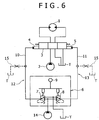
- the present invention relates to a hydraulic circuit for preventing a sudden movement of an actuator due to a rapid change in pilot pressure at the time of a rapid operation in a construction machine operating a control valve by the pilot pressure from a remote control valve and actuating a hydraulic actuator.
- the reference numeral 1 denotes a hydraulic actuator (a hydraulic motor is shown as an example).
- the reference numeral 2 denotes a main pump serving as a hydraulic source.
- the reference numeral 3 denotes a control valve of a hydraulic pilot type for controlling an action of the hydraulic actuator 1.
- the reference numerals 4 and 5 denote pilot ports on the both sides of this control valve 3.
- the reference numeral 6 denotes a remote control valve for operating the control valve 3.
- the remote control valve is formed by a pair of pressure reducing valves 7 and 8 and a lever 9 for operating the pressure reducing valves. Secondary sides of both the pressure reducing valves 7 and 8 are connected to the pilot ports 4 and 5 on the both sides of the control valve 3 through pilot tubes 10 and 11 respectively
- Pilot lines 12 and 13 for transmitting pilot pressure generated in the pressure reducing valves 7 and 8 to the control valve 3 via the pilot tubes 10 and 11 are formed.
- pilot lines 12 and 13 indicating the whole pilot pressure supplying system including the pressure reducing valves 7 and 8, the pilot tubes 10 and 11, and the control valve 3 are formed.
- the control valve 3 performs a stroke action in accordance with a lever operation amount of the remote control valve 6 so that an action of the hydraulic actuator 1 is controlled.
- the reference numeral 14 denotes a pilot pump serving as the pilot hydraulic source
- T denotes a tank.
- throttle paths (a bleed-off path having a throttle, Fig. 6 shows an example of a throttle path diverged from the pilot tubes 10 and 11) 15 communicating with tanks T are provided in the pilot lines 12 and 13 (the pilot tubes 10 and 11 or a spool of the control valve 3, or the pressure reducing valves 7 and 8).
- the pilot lines 12 and 13 the pilot tubes 10 and 11 or a spool of the control valve 3, or the pressure reducing valves 7 and 8.
- the pilot pressure should be set to be high so that the spool of the control valve 3 surely reaches a stroke end at the time of a full operation. As a result, the spool reaches the stroke end before the lever 9 of the remote control valve reaches the maximum operation amount. Therefore, the lever operation amount is in excess so that there is a disadvantage of deteriorating operability.
- the throttle path is not constantly opened over the entire spool stroke of the control valve but opened from the vicinity of the stroke where the hydraulic actuator actually starts moving after the spool starts performing the stroke action. Therefore, it is possible to decrease the leakage amount of the pilot oil from the throttle path.
- the opening area of the throttle path can be extended and the buffering function can be ensured at the time of starting up the actuator where shock is most frequently occurred due to the rapid operation. Therefore, it is possible to obtain a necessary and sufficient buffering effect.
- the pilot pressure can be set to be low in comparison to Related Art. Therefore, there is no fear that the spool early reaches a stroke end so that a useless lever stroke is occurred, and it is possible to improve operability.
- the throttle path is adapted to be closed before the spool of the control valve reaches the stroke end.
- an opening area of the throttle path is preferably adapted to be reduced in accordance with an increase in the spool stroke.
- the opening area of the throttle path is adapted to be reduced in accordance with the increase in the spool stroke, it is possible to further decrease the leakage amount.
- the throttle path may be provided in the outside of the control valve or the inside thereof.
- the throttle path of the control valve is formed by providing a notch in the spool of the control valve and a tank path communicating with the tank in a valve block thereof, there are advantages of reducing cost and saving space for the buffering function in comparison to a case where the throttle path is provided in the outside of the valve due to the facts that:
- this throttle path is formed by the notch and the tank path of the control valve, this throttle path also functions as an air-bleeding path for bleeding the air from a pilot port to the tank. This contributes to easier processing of the spool and cost reduction.
- Fig. 1 shows a hydraulic circuit according to the embodiment.
- a basic configuration of this hydraulic circuit is the same as a basic configuration of a hydraulic circuit of Related Art shown in Fig. 6 . Therefore, parts in Fig. 1 which are the same as in Fig. 6 are given the same reference numerals and a duplicated description thereof will be omitted.
- a throttle path 16 communicating with a tank T is provided in the inside of a control valve 3.
- This throttle path 16 is opened from a vicinity of a spool stroke where a hydraulic actuator 1 starts moving. That is, this throttle path 16 is opened from the vicinity of predetermined pilot pressure by which the hydraulic actuator 1 starts moving.
- Fig. 2 shows a structure of a right pilot portion of the control valve 3 in Fig. 1 as an example, the other side has the same configuration.
- the reference numeral 17 denotes a valve block serving as a main body of the control valve 3
- the reference numeral 18 denotes a spool. This spool 18 performs a stroke action by pilot pressure applied to a pilot port 5.
- a tank path 19 communicating with the tank T is provided in the valve block 17, and a notch 20 communicating with this tank path 19 at a predetermined stroke is provided in the spool 18.
- the throttle path 16 is formed by these units.
- the figures show a change state of these opening areas in accordance with the spool stroke.
- an opening part of the throttle path 16 (a part where the notch 20 communicates with the tank path 19) is shown by diagonal lines for easy distinction. Although the figures only show the relationship between the stroke and the opening areas of an action on one side, the other side has the same relationship.
- the spool 18 of Fig. 2 starts performing the stroke action to the left side in accordance with an operation of the remote control valve 6 of Fig. 1 . While the bleed-off path PT is gradually closed according to an increase in this spool stroke, the meter-in path PC is gradually opened.
- the opening area of the bleed-off path PT (a bleed-off flow rate) is rapidly reduced from start of the stroke to a stroke S 1 and slowly reduced with a gentle inclination after creating a flection point X as shown in the figure.
- the hydraulic actuator 1 starts moving at a stroke S2 slightly after the stroke S1 of the flection point X.
- the throttle path 16 starts to be opened at a stroke S3 in the vicinity of the stroke S2 where this hydraulic actuator 1 starts moving (although Fig. 3 shows that S3 is slightly after S2, S3 may be the same as or slightly before S2), and is closed at a stroke S4 right before a stroke end Se.
- the throttle path 16 is opened only within a section A1 from start of movement of the hydraulic actuator 1 to right before the stroke end among the entire spool stroke A. A part of pilot oil is dropped to the tank T through this throttle path 16. Thereby, shock at the time of a rapid operation, that is, a rapid action of the control valve 3 due to a rapid rise in the pilot pressure and a sudden movement of the hydraulic actuator 1 due to the rapid action are prevented.
- the pilot pressure can be set to be low in comparison to Related Art. Therefore, there is no fear that the spool early reaches the stroke end so that a useless lever stroke is occurred, and it is possible to improve operability.
- the opening area of the throttle path 16 is slowly reduced in accordance with the increase in the stroke at a final phase of the section A1 of opening the throttle path 16 as shown in Fig. 4 .
- this throttle path 16 is formed in the control valve 3 by the notch 20 and the tank path 19, this throttle path 16 also functions as an air-bleeding path for bleeding the air from the pilot port 5 to the tank. This contributes to easier processing of the spool and cost reduction.
- a throttle path for returning a part of pilot oil to a tank is formed by a tank path provided in a valve block of a control valve and a notch provided in a spool thereof.
- the above path is opened within a section from a vicinity of a stroke where a hydraulic actuator starts moving to right before a stroke end among a spool stroke of the control valve.
- An opening area of the above path is slowly reduced in accordance with an increase in the stroke at a final phase of the section.
Landscapes
- Engineering & Computer Science (AREA)
- Physics & Mathematics (AREA)
- Fluid Mechanics (AREA)
- Mechanical Engineering (AREA)
- General Engineering & Computer Science (AREA)
- Fluid-Pressure Circuits (AREA)
- Operation Control Of Excavators (AREA)
Claims (3)
- Circuit hydraulique pour une machine de construction, comprenant :une soupape de commande à distance (6);une soupape de commande (3) du type à pilote hydraulique avec un tiroir cylindrique (18) pour réaliser une action de course par la pression pilote à partir de ladite soupape de commande à distance (6) ;un actionneur hydraulique (1) dont l'action est commandée par ladite soupape de commande (3) ; etune trajectoire d'étranglement (16) pour ramener une partie d'huile pilote à un réservoir (T) tout en étant étranglée, ladite trajectoire d'étranglement (16) étant prévue dans une ligne pilote pour transmettre la pression pilote de ladite soupape de commande à distance (6) à ladite soupape de commande (3), dans lequel :ladite trajectoire d'étranglement (16) a une zone d'ouverture variable et est adaptée pour être fermée lorsqu'une course de tiroir cylindrique de ladite soupape de commande (3) est inférieure à une course spécifiée (S3) et être ouverte à partir d'un point où ladite course de tiroir cylindrique atteint ladite course spécifique (S3), ladite course spécifique (S3) étant à proximité d'une course (S2) dans laquelle ledit actionneur hydraulique (1) commence à se déplacer,caractérisé en ce que :ladite trajectoire d'étranglement (16) est adaptée pour être ouverte uniquement dans une section (A1) à partir du début du déplacement de l'actionneur hydraulique juste avant que le tiroir cylindrique (18) de ladite soupape de commande (3) atteigne une fin de course.
- Circuit hydraulique pour une machine de construction selon la revendication 1, dans lequel :ladite zone d'ouverture de ladite trajectoire d'étranglement (16) est adaptée pour être réduite selon une augmentation de la course du tiroir cylindrique.
- Circuit hydraulique pour une machine de construction selon la revendication 1, dans lequel :ladite trajectoire d'étranglement (16) de ladite soupape de commande (3) est formée en prévoyant une encoche (20) dans le tiroir cylindrique (18) de ladite soupape de commande (3) et une trajectoire de réservoir (19) communiquant avec le réservoir (T) dans son bloc de soupape (17).
Applications Claiming Priority (1)
| Application Number | Priority Date | Filing Date | Title |
|---|---|---|---|
| JP2008037280A JP4548494B2 (ja) | 2008-02-19 | 2008-02-19 | 建設機械の油圧回路 |
Publications (3)
| Publication Number | Publication Date |
|---|---|
| EP2093431A2 EP2093431A2 (fr) | 2009-08-26 |
| EP2093431A3 EP2093431A3 (fr) | 2012-03-28 |
| EP2093431B1 true EP2093431B1 (fr) | 2017-06-07 |
Family
ID=40723206
Family Applications (1)
| Application Number | Title | Priority Date | Filing Date |
|---|---|---|---|
| EP08173059.0A Not-in-force EP2093431B1 (fr) | 2008-02-19 | 2008-12-30 | Circuit hydraulique d'une machine de construction |
Country Status (3)
| Country | Link |
|---|---|
| US (1) | US8151688B2 (fr) |
| EP (1) | EP2093431B1 (fr) |
| JP (1) | JP4548494B2 (fr) |
Families Citing this family (6)
| Publication number | Priority date | Publication date | Assignee | Title |
|---|---|---|---|---|
| JP5916450B2 (ja) | 2012-03-15 | 2016-05-11 | Kyb株式会社 | 切換バルブ |
| CN103243772A (zh) * | 2013-05-08 | 2013-08-14 | 三一重机有限公司 | 工程机械及其操纵控制系统 |
| EP3009690A4 (fr) * | 2013-06-14 | 2017-01-25 | Volvo Construction Equipment AB | Soupape de commande de débit pour machine de construction |
| JP6475522B2 (ja) * | 2015-03-13 | 2019-02-27 | 川崎重工業株式会社 | 油圧システム |
| KR102666808B1 (ko) * | 2019-02-13 | 2024-05-17 | 에이치디현대인프라코어 주식회사 | 굴삭기의 선회 제어 방법, 이를 수행하기 위한 선회 제어 밸브 및 선회 제어 밸브를 포함하는 굴삭기의 선회 제어 장치 |
| JP2025149337A (ja) | 2024-03-26 | 2025-10-08 | 株式会社クボタ | 作業機及び作業機の制御方法 |
Citations (2)
| Publication number | Priority date | Publication date | Assignee | Title |
|---|---|---|---|---|
| JP2001208005A (ja) * | 2000-01-28 | 2001-08-03 | Hitachi Constr Mach Co Ltd | 油圧パイロット駆動式操作回路 |
| JP2003172310A (ja) * | 2001-12-04 | 2003-06-20 | Nachi Fujikoshi Corp | 油圧パイロット駆動方向切換弁 |
Family Cites Families (9)
| Publication number | Priority date | Publication date | Assignee | Title |
|---|---|---|---|---|
| JPS59126184A (ja) | 1982-12-29 | 1984-07-20 | Kawasaki Heavy Ind Ltd | 方向切換弁 |
| JPH0325441Y2 (fr) * | 1986-07-09 | 1991-06-03 | ||
| DE3840328A1 (de) | 1988-11-30 | 1990-05-31 | Bosch Gmbh Robert | Vorgesteuertes wegeventil |
| JPH08326708A (ja) * | 1995-05-26 | 1996-12-10 | Hitachi Constr Mach Co Ltd | 減圧弁型パイロット弁 |
| JPH09235756A (ja) * | 1996-02-28 | 1997-09-09 | Yutani Heavy Ind Ltd | 油圧リモコン回路 |
| US5996464A (en) | 1998-12-07 | 1999-12-07 | Woodward Governor Company | Fail safe valve and multiplexed fluid control systems incorporating the same |
| JP2001165349A (ja) * | 1999-12-09 | 2001-06-22 | Hitachi Constr Mach Co Ltd | 方向制御弁 |
| JP3772982B2 (ja) * | 2003-02-28 | 2006-05-10 | 住友建機製造株式会社 | 建設機械のリモコン弁油圧回路 |
| JP2006125627A (ja) | 2004-09-29 | 2006-05-18 | Kobelco Contstruction Machinery Ltd | 建設機械の油圧回路 |
-
2008
- 2008-02-19 JP JP2008037280A patent/JP4548494B2/ja active Active
- 2008-12-19 US US12/339,813 patent/US8151688B2/en active Active
- 2008-12-30 EP EP08173059.0A patent/EP2093431B1/fr not_active Not-in-force
Patent Citations (2)
| Publication number | Priority date | Publication date | Assignee | Title |
|---|---|---|---|---|
| JP2001208005A (ja) * | 2000-01-28 | 2001-08-03 | Hitachi Constr Mach Co Ltd | 油圧パイロット駆動式操作回路 |
| JP2003172310A (ja) * | 2001-12-04 | 2003-06-20 | Nachi Fujikoshi Corp | 油圧パイロット駆動方向切換弁 |
Also Published As
| Publication number | Publication date |
|---|---|
| JP2009197822A (ja) | 2009-09-03 |
| EP2093431A3 (fr) | 2012-03-28 |
| JP4548494B2 (ja) | 2010-09-22 |
| EP2093431A2 (fr) | 2009-08-26 |
| US8151688B2 (en) | 2012-04-10 |
| US20090205723A1 (en) | 2009-08-20 |
Similar Documents
| Publication | Publication Date | Title |
|---|---|---|
| EP2093431B1 (fr) | Circuit hydraulique d'une machine de construction | |
| EP2071195B1 (fr) | Circuit hydraulique avec soupapes de maintien de charge commandées par pression pilote externe | |
| US7513109B2 (en) | Hydraulic controller for working machine | |
| WO2019138636A1 (fr) | Circuit hydraulique | |
| EP3587674B1 (fr) | Système de commande d'engin de chantier et procédé de commande d'engin de chantier | |
| EP1726723B1 (fr) | Engin de travaux publics | |
| JP7474346B2 (ja) | 方向・流量制御弁および液圧システム | |
| JP2013508647A (ja) | バルブ固着の安全機構 | |
| JP6196567B2 (ja) | 建設機械の油圧駆動システム | |
| JP2015137678A (ja) | 流体圧システム | |
| JP2014148994A (ja) | 作業機械の油圧制御装置 | |
| JP4432707B2 (ja) | 建設機械の油圧制御回路 | |
| JP4859786B2 (ja) | 制御装置 | |
| WO2022131195A1 (fr) | Unité vanne et dispositif vanne | |
| JP2002022054A (ja) | 方向制御弁 | |
| JP2003120605A (ja) | 油圧機械の油圧駆動装置 | |
| JP2016161044A (ja) | 液圧駆動システム | |
| JP2021173390A (ja) | 油圧制御回路 | |
| JP2021025232A (ja) | 建設機械 | |
| JP5775292B2 (ja) | パイロット操作切換弁を備えたショック緩和回路 | |
| JP4875687B2 (ja) | 油圧制御装置 | |
| JP2009024393A (ja) | 流体制御回路および作業機械 | |
| JP2008298184A (ja) | 油圧駆動装置 | |
| WO2025234163A1 (fr) | Système hydraulique et dispositif de commande | |
| JP2007270982A (ja) | 建設機械の油圧制御装置 |
Legal Events
| Date | Code | Title | Description |
|---|---|---|---|
| PUAI | Public reference made under article 153(3) epc to a published international application that has entered the european phase |
Free format text: ORIGINAL CODE: 0009012 |
|
| 17P | Request for examination filed |
Effective date: 20081230 |
|
| AK | Designated contracting states |
Kind code of ref document: A2 Designated state(s): AT BE BG CH CY CZ DE DK EE ES FI FR GB GR HR HU IE IS IT LI LT LU LV MC MT NL NO PL PT RO SE SI SK TR |
|
| AX | Request for extension of the european patent |
Extension state: AL BA MK RS |
|
| PUAL | Search report despatched |
Free format text: ORIGINAL CODE: 0009013 |
|
| AK | Designated contracting states |
Kind code of ref document: A3 Designated state(s): AT BE BG CH CY CZ DE DK EE ES FI FR GB GR HR HU IE IS IT LI LT LU LV MC MT NL NO PL PT RO SE SI SK TR |
|
| AX | Request for extension of the european patent |
Extension state: AL BA MK RS |
|
| RIC1 | Information provided on ipc code assigned before grant |
Ipc: F15B 13/04 20060101ALI20120221BHEP Ipc: F15B 13/042 20060101AFI20120221BHEP |
|
| 17Q | First examination report despatched |
Effective date: 20120905 |
|
| AKX | Designation fees paid |
Designated state(s): AT BE BG CH CY CZ DE DK EE ES FI FR GB GR HR HU IE IS IT LI LT LU LV MC MT NL NO PL PT RO SE SI SK TR |
|
| GRAP | Despatch of communication of intention to grant a patent |
Free format text: ORIGINAL CODE: EPIDOSNIGR1 |
|
| STAA | Information on the status of an ep patent application or granted ep patent |
Free format text: STATUS: GRANT OF PATENT IS INTENDED |
|
| INTG | Intention to grant announced |
Effective date: 20161220 |
|
| RIN1 | Information on inventor provided before grant (corrected) |
Inventor name: SAOTOME, YOSHIMI Inventor name: SHIRAGA, NORIFUMI |
|
| GRAS | Grant fee paid |
Free format text: ORIGINAL CODE: EPIDOSNIGR3 |
|
| GRAA | (expected) grant |
Free format text: ORIGINAL CODE: 0009210 |
|
| STAA | Information on the status of an ep patent application or granted ep patent |
Free format text: STATUS: THE PATENT HAS BEEN GRANTED |
|
| AK | Designated contracting states |
Kind code of ref document: B1 Designated state(s): AT BE BG CH CY CZ DE DK EE ES FI FR GB GR HR HU IE IS IT LI LT LU LV MC MT NL NO PL PT RO SE SI SK TR |
|
| REG | Reference to a national code |
Ref country code: GB Ref legal event code: FG4D |
|
| GRAA | (expected) grant |
Free format text: ORIGINAL CODE: 0009210 |
|
| REG | Reference to a national code |
Ref country code: CH Ref legal event code: EP Ref country code: AT Ref legal event code: REF Ref document number: 899456 Country of ref document: AT Kind code of ref document: T Effective date: 20170615 |
|
| REG | Reference to a national code |
Ref country code: IE Ref legal event code: FG4D |
|
| REG | Reference to a national code |
Ref country code: DE Ref legal event code: R096 Ref document number: 602008050555 Country of ref document: DE |
|
| REG | Reference to a national code |
Ref country code: NL Ref legal event code: MP Effective date: 20170607 |
|
| REG | Reference to a national code |
Ref country code: LT Ref legal event code: MG4D |
|
| PG25 | Lapsed in a contracting state [announced via postgrant information from national office to epo] |
Ref country code: NO Free format text: LAPSE BECAUSE OF FAILURE TO SUBMIT A TRANSLATION OF THE DESCRIPTION OR TO PAY THE FEE WITHIN THE PRESCRIBED TIME-LIMIT Effective date: 20170907 Ref country code: LT Free format text: LAPSE BECAUSE OF FAILURE TO SUBMIT A TRANSLATION OF THE DESCRIPTION OR TO PAY THE FEE WITHIN THE PRESCRIBED TIME-LIMIT Effective date: 20170607 Ref country code: HR Free format text: LAPSE BECAUSE OF FAILURE TO SUBMIT A TRANSLATION OF THE DESCRIPTION OR TO PAY THE FEE WITHIN THE PRESCRIBED TIME-LIMIT Effective date: 20170607 Ref country code: GR Free format text: LAPSE BECAUSE OF FAILURE TO SUBMIT A TRANSLATION OF THE DESCRIPTION OR TO PAY THE FEE WITHIN THE PRESCRIBED TIME-LIMIT Effective date: 20170908 Ref country code: FI Free format text: LAPSE BECAUSE OF FAILURE TO SUBMIT A TRANSLATION OF THE DESCRIPTION OR TO PAY THE FEE WITHIN THE PRESCRIBED TIME-LIMIT Effective date: 20170607 Ref country code: ES Free format text: LAPSE BECAUSE OF FAILURE TO SUBMIT A TRANSLATION OF THE DESCRIPTION OR TO PAY THE FEE WITHIN THE PRESCRIBED TIME-LIMIT Effective date: 20170607 |
|
| REG | Reference to a national code |
Ref country code: AT Ref legal event code: MK05 Ref document number: 899456 Country of ref document: AT Kind code of ref document: T Effective date: 20170607 |
|
| PG25 | Lapsed in a contracting state [announced via postgrant information from national office to epo] |
Ref country code: NL Free format text: LAPSE BECAUSE OF FAILURE TO SUBMIT A TRANSLATION OF THE DESCRIPTION OR TO PAY THE FEE WITHIN THE PRESCRIBED TIME-LIMIT Effective date: 20170607 Ref country code: BG Free format text: LAPSE BECAUSE OF FAILURE TO SUBMIT A TRANSLATION OF THE DESCRIPTION OR TO PAY THE FEE WITHIN THE PRESCRIBED TIME-LIMIT Effective date: 20170907 Ref country code: SE Free format text: LAPSE BECAUSE OF FAILURE TO SUBMIT A TRANSLATION OF THE DESCRIPTION OR TO PAY THE FEE WITHIN THE PRESCRIBED TIME-LIMIT Effective date: 20170607 Ref country code: LV Free format text: LAPSE BECAUSE OF FAILURE TO SUBMIT A TRANSLATION OF THE DESCRIPTION OR TO PAY THE FEE WITHIN THE PRESCRIBED TIME-LIMIT Effective date: 20170607 |
|
| REG | Reference to a national code |
Ref country code: FR Ref legal event code: PLFP Year of fee payment: 10 |
|
| PG25 | Lapsed in a contracting state [announced via postgrant information from national office to epo] |
Ref country code: CZ Free format text: LAPSE BECAUSE OF FAILURE TO SUBMIT A TRANSLATION OF THE DESCRIPTION OR TO PAY THE FEE WITHIN THE PRESCRIBED TIME-LIMIT Effective date: 20170607 Ref country code: RO Free format text: LAPSE BECAUSE OF FAILURE TO SUBMIT A TRANSLATION OF THE DESCRIPTION OR TO PAY THE FEE WITHIN THE PRESCRIBED TIME-LIMIT Effective date: 20170607 Ref country code: AT Free format text: LAPSE BECAUSE OF FAILURE TO SUBMIT A TRANSLATION OF THE DESCRIPTION OR TO PAY THE FEE WITHIN THE PRESCRIBED TIME-LIMIT Effective date: 20170607 Ref country code: SK Free format text: LAPSE BECAUSE OF FAILURE TO SUBMIT A TRANSLATION OF THE DESCRIPTION OR TO PAY THE FEE WITHIN THE PRESCRIBED TIME-LIMIT Effective date: 20170607 Ref country code: EE Free format text: LAPSE BECAUSE OF FAILURE TO SUBMIT A TRANSLATION OF THE DESCRIPTION OR TO PAY THE FEE WITHIN THE PRESCRIBED TIME-LIMIT Effective date: 20170607 |
|
| PG25 | Lapsed in a contracting state [announced via postgrant information from national office to epo] |
Ref country code: PL Free format text: LAPSE BECAUSE OF FAILURE TO SUBMIT A TRANSLATION OF THE DESCRIPTION OR TO PAY THE FEE WITHIN THE PRESCRIBED TIME-LIMIT Effective date: 20170607 Ref country code: IS Free format text: LAPSE BECAUSE OF FAILURE TO SUBMIT A TRANSLATION OF THE DESCRIPTION OR TO PAY THE FEE WITHIN THE PRESCRIBED TIME-LIMIT Effective date: 20171007 |
|
| REG | Reference to a national code |
Ref country code: DE Ref legal event code: R097 Ref document number: 602008050555 Country of ref document: DE |
|
| PLBE | No opposition filed within time limit |
Free format text: ORIGINAL CODE: 0009261 |
|
| STAA | Information on the status of an ep patent application or granted ep patent |
Free format text: STATUS: NO OPPOSITION FILED WITHIN TIME LIMIT |
|
| PG25 | Lapsed in a contracting state [announced via postgrant information from national office to epo] |
Ref country code: DK Free format text: LAPSE BECAUSE OF FAILURE TO SUBMIT A TRANSLATION OF THE DESCRIPTION OR TO PAY THE FEE WITHIN THE PRESCRIBED TIME-LIMIT Effective date: 20170607 |
|
| 26N | No opposition filed |
Effective date: 20180308 |
|
| PG25 | Lapsed in a contracting state [announced via postgrant information from national office to epo] |
Ref country code: SI Free format text: LAPSE BECAUSE OF FAILURE TO SUBMIT A TRANSLATION OF THE DESCRIPTION OR TO PAY THE FEE WITHIN THE PRESCRIBED TIME-LIMIT Effective date: 20170607 |
|
| REG | Reference to a national code |
Ref country code: CH Ref legal event code: PL |
|
| PG25 | Lapsed in a contracting state [announced via postgrant information from national office to epo] |
Ref country code: MT Free format text: LAPSE BECAUSE OF NON-PAYMENT OF DUE FEES Effective date: 20171230 Ref country code: LU Free format text: LAPSE BECAUSE OF NON-PAYMENT OF DUE FEES Effective date: 20171230 |
|
| REG | Reference to a national code |
Ref country code: IE Ref legal event code: MM4A |
|
| REG | Reference to a national code |
Ref country code: BE Ref legal event code: MM Effective date: 20171231 |
|
| PG25 | Lapsed in a contracting state [announced via postgrant information from national office to epo] |
Ref country code: IE Free format text: LAPSE BECAUSE OF NON-PAYMENT OF DUE FEES Effective date: 20171230 |
|
| PG25 | Lapsed in a contracting state [announced via postgrant information from national office to epo] |
Ref country code: LI Free format text: LAPSE BECAUSE OF NON-PAYMENT OF DUE FEES Effective date: 20171231 Ref country code: BE Free format text: LAPSE BECAUSE OF NON-PAYMENT OF DUE FEES Effective date: 20171231 Ref country code: CH Free format text: LAPSE BECAUSE OF NON-PAYMENT OF DUE FEES Effective date: 20171231 |
|
| PG25 | Lapsed in a contracting state [announced via postgrant information from national office to epo] |
Ref country code: HU Free format text: LAPSE BECAUSE OF FAILURE TO SUBMIT A TRANSLATION OF THE DESCRIPTION OR TO PAY THE FEE WITHIN THE PRESCRIBED TIME-LIMIT; INVALID AB INITIO Effective date: 20081230 Ref country code: MC Free format text: LAPSE BECAUSE OF FAILURE TO SUBMIT A TRANSLATION OF THE DESCRIPTION OR TO PAY THE FEE WITHIN THE PRESCRIBED TIME-LIMIT Effective date: 20170607 |
|
| PG25 | Lapsed in a contracting state [announced via postgrant information from national office to epo] |
Ref country code: CY Free format text: LAPSE BECAUSE OF NON-PAYMENT OF DUE FEES Effective date: 20170607 |
|
| PG25 | Lapsed in a contracting state [announced via postgrant information from national office to epo] |
Ref country code: TR Free format text: LAPSE BECAUSE OF FAILURE TO SUBMIT A TRANSLATION OF THE DESCRIPTION OR TO PAY THE FEE WITHIN THE PRESCRIBED TIME-LIMIT Effective date: 20170607 |
|
| PG25 | Lapsed in a contracting state [announced via postgrant information from national office to epo] |
Ref country code: PT Free format text: LAPSE BECAUSE OF FAILURE TO SUBMIT A TRANSLATION OF THE DESCRIPTION OR TO PAY THE FEE WITHIN THE PRESCRIBED TIME-LIMIT Effective date: 20170607 |
|
| PGFP | Annual fee paid to national office [announced via postgrant information from national office to epo] |
Ref country code: GB Payment date: 20231109 Year of fee payment: 16 |
|
| PGFP | Annual fee paid to national office [announced via postgrant information from national office to epo] |
Ref country code: IT Payment date: 20231110 Year of fee payment: 16 Ref country code: FR Payment date: 20231108 Year of fee payment: 16 Ref country code: DE Payment date: 20231107 Year of fee payment: 16 |
|
| REG | Reference to a national code |
Ref country code: DE Ref legal event code: R119 Ref document number: 602008050555 Country of ref document: DE |
|
| GBPC | Gb: european patent ceased through non-payment of renewal fee |
Effective date: 20241230 |
|
| PG25 | Lapsed in a contracting state [announced via postgrant information from national office to epo] |
Ref country code: DE Free format text: LAPSE BECAUSE OF NON-PAYMENT OF DUE FEES Effective date: 20250701 |
|
| PG25 | Lapsed in a contracting state [announced via postgrant information from national office to epo] |
Ref country code: IT Free format text: LAPSE BECAUSE OF NON-PAYMENT OF DUE FEES Effective date: 20241230 |
|
| PG25 | Lapsed in a contracting state [announced via postgrant information from national office to epo] |
Ref country code: GB Free format text: LAPSE BECAUSE OF NON-PAYMENT OF DUE FEES Effective date: 20241230 |
|
| PG25 | Lapsed in a contracting state [announced via postgrant information from national office to epo] |
Ref country code: FR Free format text: LAPSE BECAUSE OF NON-PAYMENT OF DUE FEES Effective date: 20241231 |