EP2093455A2 - Ensemble guide de tige magnétorhéologique (MR) et amortisseur MR doté de celui-ci - Google Patents
Ensemble guide de tige magnétorhéologique (MR) et amortisseur MR doté de celui-ci Download PDFInfo
- Publication number
- EP2093455A2 EP2093455A2 EP09151951A EP09151951A EP2093455A2 EP 2093455 A2 EP2093455 A2 EP 2093455A2 EP 09151951 A EP09151951 A EP 09151951A EP 09151951 A EP09151951 A EP 09151951A EP 2093455 A2 EP2093455 A2 EP 2093455A2
- Authority
- EP
- European Patent Office
- Prior art keywords
- seal
- bore
- rod guide
- disposed
- housing
- Prior art date
- Legal status (The legal status is an assumption and is not a legal conclusion. Google has not performed a legal analysis and makes no representation as to the accuracy of the status listed.)
- Granted
Links
Images

Classifications
-
- F—MECHANICAL ENGINEERING; LIGHTING; HEATING; WEAPONS; BLASTING
- F16—ENGINEERING ELEMENTS AND UNITS; GENERAL MEASURES FOR PRODUCING AND MAINTAINING EFFECTIVE FUNCTIONING OF MACHINES OR INSTALLATIONS; THERMAL INSULATION IN GENERAL
- F16F—SPRINGS; SHOCK-ABSORBERS; MEANS FOR DAMPING VIBRATION
- F16F9/00—Springs, vibration-dampers, shock-absorbers, or similarly-constructed movement-dampers using a fluid or the equivalent as damping medium
- F16F9/32—Details
- F16F9/53—Means for adjusting damping characteristics by varying fluid viscosity, e.g. electromagnetically
- F16F9/535—Magnetorheological [MR] fluid dampers
-
- F—MECHANICAL ENGINEERING; LIGHTING; HEATING; WEAPONS; BLASTING
- F16—ENGINEERING ELEMENTS AND UNITS; GENERAL MEASURES FOR PRODUCING AND MAINTAINING EFFECTIVE FUNCTIONING OF MACHINES OR INSTALLATIONS; THERMAL INSULATION IN GENERAL
- F16F—SPRINGS; SHOCK-ABSORBERS; MEANS FOR DAMPING VIBRATION
- F16F9/00—Springs, vibration-dampers, shock-absorbers, or similarly-constructed movement-dampers using a fluid or the equivalent as damping medium
- F16F9/32—Details
- F16F9/3285—Details for filtering
-
- F—MECHANICAL ENGINEERING; LIGHTING; HEATING; WEAPONS; BLASTING
- F16—ENGINEERING ELEMENTS AND UNITS; GENERAL MEASURES FOR PRODUCING AND MAINTAINING EFFECTIVE FUNCTIONING OF MACHINES OR INSTALLATIONS; THERMAL INSULATION IN GENERAL
- F16F—SPRINGS; SHOCK-ABSORBERS; MEANS FOR DAMPING VIBRATION
- F16F9/00—Springs, vibration-dampers, shock-absorbers, or similarly-constructed movement-dampers using a fluid or the equivalent as damping medium
- F16F9/32—Details
- F16F9/36—Special sealings, including sealings or guides for piston-rods
- F16F9/362—Combination of sealing and guide arrangements for piston rods
Definitions
- the present invention relates generally to magnetorheological devices, and more particularly to a magnetorheological (MR) rod guide assembly and to an MR damper having an MR rod guide assembly.
- MR magnetorheological
- Conventional magnetorheological (MR) dampers include an MR damper having an annular cylinder, an MR piston, an MR piston rod, and an MR rod guide assembly.
- the annular cylinder has a top end and a bottom end.
- the MR piston is positioned in the cylinder, and the MR piston rod is attached to the MR piston and has one end extending outside the top end of the cylinder.
- the MR rod guide assembly includes a housing, two (primary and buffer) annular seals, an annular rod guide (also called a porous insert), a split bearing, and either an annular, plastic, piston-impact bumper or an annular, metallic piston-impact plate, depending on the application, wherein the bumper or plate, in addition to being designed to take up the impact from the piston at rebound, must also be designed to retain the buffer seal and to have added holes for flow to reach the porous insert.
- the housing is attached to the cylinder at the top end and has a through bore.
- the two seals are positioned in the through bore and sealingly contact the MR piston rod.
- the rod guide is positioned in the through bore and is attached to the housing.
- the split bearing is positioned in and attached to the rod guide and contacts and slidingly receives the MR piston rod.
- the primary seal is self-attached and has a lip which is positioned in a seal gland of the housing.
- a seal retainer attached to the housing secures the buffer seal in the rod guide.
- the plastic piston-impact bumper is attached to the bottom of the housing.
- the annular rod guide is a porous, powdered-metal rod guide which acts as a filter to filter out (e.g., iron) particles in the MR fluid to allow clear fluid to lubricate the MR piston rod as it slides into the bearing.
- the rod guide is made by expensive machining of a porous, powdered-metal right-circular cylinder to create the annulus including different diameter portions to accommodate the bearing and the buffer seal.
- a first expression of an embodiment of the invention is for a magnetorheological (MR) rod guide assembly including a nonporous MR-rod-guide-assembly housing, an annular first seal, an annular second seal, and a non-annular, porous filter plug.
- the housing has a central longitudinal axis and includes a through bore coaxially aligned with the longitudinal axis.
- the first seal is coaxially aligned with the longitudinal axis, is positioned in the through bore, and is adapted to sealingly contact an MR piston rod.
- the second seal is coaxially aligned with the longitudinal axis, is positioned in the through bore, is longitudinally spaced apart from the first seal defining an inter-seal bore portion of the through bore, and is adapted to sealingly contact the MR piston rod.
- the filter plug is positioned in the housing, has a longitudinal first end in a first fluid communication with the through bore longitudinally outside the inter-seal bore portion, and has a longitudinal second end in a second fluid communication with the through bore longitudinally within the inter-seal bore portion.
- a second expression of an embodiment of the invention is for a magnetorheological (MR) rod guide assembly including a monolithic, nonporous MR-rod-guide-assembly housing, annular first and second seals, an annular, nonporous rod guide, a split bearing, and a non-annular, cylindrical, porous filter plug.
- the housing has a central longitudinal axis and includes a through bore coaxially aligned with the longitudinal axis.
- the first and second seals are positioned in the through bore, are adapted to sealingly contact an MR piston rod, and are longitudinally spaced apart defining an inter-seal portion of the through bore.
- the first seal is attached to the housing.
- the rod guide is positioned in the inter-seal portion of the through bore and is attached to the housing.
- the second seal is self-attached to the rod guide.
- the split bearing is positioned within and attached to the rod guide and is adapted to contact and slidingly receive the MR piston rod.
- the porous filter plug is not coaxially aligned with the longitudinal axis, is positioned in the housing radially outward of the rod guide, has a longitudinal first end in fluid communication with the through bore longitudinally outside the inter-seal bore portion, and has a longitudinal second end in fluid communication with the through bore longitudinally within the inter-seal bore portion.
- a third expression of an embodiment of the invention is for a magnetorheological (MR) damper including an annular cylinder, an MR piston, an MR piston rod, and an MR rod guide assembly.
- the cylinder has a top end and a bottom end.
- the MR piston is positioned in the cylinder.
- the MR piston rod is attached to the MR piston and has one end extending outside the top end of the cylinder.
- the MR rod guide assembly includes a monolithic, nonporous MR-rod-guide-assembly housing, annular first and second seals, an annular, nonporous rod guide, a split bearing, and a non-annular, cylindrical, porous filter plug.
- the housing has a central longitudinal axis, is attached to the cylinder at the top end, and includes a through bore coaxially aligned with the longitudinal axis.
- the first and second seals are positioned in the through bore, are adapted to sealingly contact the MR piston rod, and are longitudinally spaced apart defining an inter-seal portion of the through bore.
- the first seal is attached to the housing.
- the rod guide is positioned in the inter-seal portion of the through bore and is attached to the housing.
- the second seal is self-attached to the rod guide.
- the split bearing is positioned within and attached to the rod guide and is adapted to contact and slidingly receive the MR piston rod.
- the filter plug is not coaxially aligned with the longitudinal axis, is disposed in the housing radially outward of the rod guide, has a longitudinal first end in fluid communication with the through bore outside the inter-seal bore portion, and has a longitudinal second end in fluid communication with the through bore within the inter-seal bore portion.
- the rod guide being nonporous, can be made from a less expensive and more easily machined material compared to a conventional rod guide (porous insert) which is porous and acts as the filter.
- a more compact design of a rod guide assembly is achieved because the second seal is self-retained to the rod guide instead of conventionally requiring a separate seal retainer.
- impact of the piston against the rod guide housing is taken up by a simple, less expensive, annular, metallic, piston-impact plate instead of the more complicated, conventional, bumper or plate designs that also must retain the buffer seal and also must add holes to allow flow to reach the porous insert.
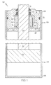
- Figure 1 is a schematic, cross-sectional view of an embodiment of the invention showing an MR damper including an MR rod guide assembly;
- Figure 2 is a view of the MR rod guide assembly of figure 1 without any other components of the MR damper of figure 1 ;
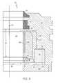
- Figure 3 is an enlarged view of a portion of figure 2 showing first and second fluid communications of the filter plug with the through bore;
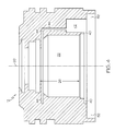
- Figure 4 is a view of the MR-rod-guide-assembly housing of the MR rod guide assembly of figure 2 showing the through bore and without any of the other components of the MR rod guide assembly seen in figure 2 .
- FIG. 1 A first expression of the embodiment of figures 1-4 is for a magnetorheological (MR) rod guide assembly 10 including a nonporous MR-rod-guide-assembly housing 12, an annular first seal 14, an annular second seal 16, and a non-annular, porous filter plug 18.
- the housing 12 has a central longitudinal axis 20 and includes a through bore 22 coaxially aligned with the longitudinal axis 20.
- the first seal 14 is coaxially aligned with the longitudinal axis 20, is disposed in the through bore 22, and is adapted to sealingly contact an MR piston rod 24.
- the second seal 16 is coaxially aligned with the longitudinal axis 20, is disposed in the through bore 22, is longitudinally spaced apart from the first seal 14 defining an inter-seal bore portion 26 of the through bore 22, and is adapted to sealingly contact the MR piston rod 24.
- the filter plug 18 is disposed in the housing 12, has a longitudinal first end 28 in a first fluid communication 30 (shown by a dashed arrowhead lines) with the through bore 22 longitudinally outside the inter-seal bore portion 26, and has a longitudinal second end 32 in a second fluid communication 34 (shown by a dashed arrowhead lines) with the through bore 22 longitudinally within the inter-seal bore portion 26.
- coaxially aligned means substantially coaxially aligned
- couplingly contact means to contact in a substantially sealing manner
- the filter plug 18 consists essentially of powdered metal.
- the filter plug 18 has a shape of a substantially right-circular cylinder.
- the filter plug 18 consists of essentially powdered steel, such as powdered stainless steel. Other shapes and compositions of the porous filter plug are left to those skilled in the art.
- the housing 12 consists essentially of nonporous aluminum
- the first seal 14 consists essentially of NBR (nitrile-butadiene rubber)
- the second seal 16 consists essentially of plastic.
- a second expression of the embodiment of figures 1-4 is for a magnetorheological (MR) rod guide assembly 10 including a monolithic, nonporous MR-rod-guide-assembly housing 12, annular first and second seals 14 and 16, an annular, nonporous rod guide 36, a split bearing 38, and a non-annular, cylindrical, porous filter plug 18.
- the housing 12 has a central longitudinal axis 20 and includes a through bore 22 coaxially aligned with the longitudinal axis 20.
- the first and second seals 14 and 16 are disposed in the through bore 22, are adapted to sealingly contact an MR piston rod 24, and are longitudinally spaced apart defining an inter-seal portion 26 of the through bore 22.
- the first seal 14 is attached (such as self-attached) to the housing 12.
- the rod guide 36 is disposed in the inter-seal portion 26 of the through bore 22 and is attached (such as self-attached) to the housing 12.
- the second seal 16 is self-attached to the rod guide 36.
- the split bearing 38 is disposed within and attached (such as self-attached) to the rod guide 36 and is adapted to contact and slidingly receive the MR piston rod 24.
- the filter plug 18 is not coaxially aligned with the longitudinal axis 20, is disposed in the housing 12 radially outward of the rod guide 36, has a longitudinal first end 28 in fluid communication with the through bore 22 longitudinally outside the inter-seal bore portion 26, and has a longitudinal second end 32 in fluid communication with the through bore 22 longitudinally within the inter-seal bore portion 26.
- a "self-attached seal” is a seal which is attached without a seal retainer.
- self-attaching annular seals include, without limitation, spring-biased elastomeric seals and resilient plastic seals self attached to nonporous members.
- self-attaching non-seals include, without limitation, resilient, open-biased split bearings and press-fit nonporous rod guides. Other examples are left to the artisan.
- the filter plug 18 consists essentially of powdered metal. In the same or a different construction, the filter plug 18 has a shape of a substantially right-circular cylinder.
- the through bore 22 has a first transversely-outwardly-extending portion 40 which is disposed longitudinally outside the inter-seal bore portion 26 and proximate the second seal 16.
- transversely-outwardly-extending is meant extending outwardly in a direction substantially perpendicular to the longitudinal axis 20.
- the housing 12 has a longitudinally-facing recess 42 which is open to the first transversely-extending portion 40.
- the filter plug 18 is disposed in the recess 42 and is attached (such as self attached by a press fit) to the housing 12.
- the through bore 22 has a second transversely-outwardly-extending portion 44 which is disposed longitudinally inside the inter-seal bore portion 26 and proximate the first seal 14.
- the housing 12 includes an internal fluid passage 46 extending longitudinally from the recess 42 to the second transversely-outwardly-extending portion 44.
- the rod guide 36 includes a first seal gland 48, and the second seal 16 has a lip 50 which is disposed in the first seal gland 48.
- the rod guide 36 consists essentially of nonporous aluminum or nonporous steel.
- the through bore 22 includes a third transversely-outwardly-extending portion 52 which longitudinally abuts and extends further (i.e., which extends transversely-outwardly further) than the second transversely-outwardly-extending portion 44, wherein the second transversely-outwardly-extending portion 44 is disposed longitudinally between the rod guide 36 and the third transversely-outwardly-extending portion 52.
- the MR rod guide assembly 10 also includes an annular, metallic piston-impact plate 54 coaxially aligned with the longitudinal axis 28, disposed in the third transversely-outwardly-extending portion 52, and attached to the housing 12, wherein the piston-impact plate 54 is devoid of any hole which does not intersect the longitudinal axis 28.
- the impact plate 54 consists essentially of nonporous steel.
- the housing 12 is radially peened to secure the impact plate 54 to the housing 12.
- a third expression of the embodiment of figures 1-4 is for a magnetorheological (MR) damper 56 including an annular cylinder 58, an MR piston 60, an MR piston rod 24, and an MR rod guide assembly 10.
- the cylinder 58 has a top end 64 and a bottom end 66. It is noted that the terms “top” and “bottom” are used merely to distinguish between the two ends of the cylinder 58 and not to describe the orientation of the cylinder 58.
- the MR piston 60 is positioned in the cylinder 58.
- the MR piston rod 24 is attached to the MR piston 60 and has one end extending outside the top end 64 of the cylinder 58.
- the MR rod guide assembly 10 includes a monolithic, nonporous MR-rod-guide-assembly housing 12, annular first and second seals 14 and 16, an annular, nonporous rod guide 36, a split bearing 38, and a non-annular, cylindrical, porous filter plug 18.
- the housing 12 has a central longitudinal axis 20, is attached to the cylinder 58 at the top end 64, and includes a through bore 22 coaxially aligned with the longitudinal axis 20.
- the first and second seals 14 and 16 are positioned in the through bore 22, are adapted to sealingly contact the MR piston rod 24, and are longitudinally spaced apart defining an inter-seal portion 26 of the through bore 22.
- the first seal 14 is attached (such as self-attached) to the housing 12.
- the rod guide 36 is disposed in the inter-seal portion 26 of the through bore 22 and is attached (such as self-attached) to the housing 12.
- the second seal 16 is self-attached to the rod guide 36.
- the split bearing 38 is positioned within and attached (such as self-attached) to the rod guide 36 and is adapted to contact and slidingly receive the MR piston rod 24.
- the filter plug 18 is not coaxially aligned with the longitudinal axis 20, is disposed in the housing 12 radially outward of the rod guide 36, has a longitudinal first end 28 in fluid communication with the through bore 22 outside the inter-seal bore portion 26, and has a longitudinal second end 32 in fluid communication with the through bore 22 within the inter-seal bore portion 26.
- the first seal 14 (sometimes called the primary seal) is disposed closer to the top end 64 of the cylinder 58, and the second seal 16 (sometimes called the buffer seal) is disposed closer to the bottom end 66 of the cylinder 58.
- the MR rod guide assembly 10 also includes a third seal 70 (sometimes called the wiper seal), wherein the first seal 14 is disposed longitudinally between the third seal 70 and the second seal 16.
- the third seal 70 consists essentially of NBR.
- at least one elastomeric O-ring seal 72 is disposed radially between and in contact with the housing 12 and the cylinder 58.
- MR fluid (not shown) is disposed in the cylinder 58 between and in contact with the bottom end 66 of the cylinder 58 and the MR rod guide assembly 10.
- the rod guide 36 is a monolithic rod guide
- the filter plug 18 is a monolithic filter plug.
- the recess 42 is a wider hole drilled in the housing 12
- the internal fluid passage 46 is a narrower hole drilled in the housing 12 from the recess 42. The number of narrower holes is left to the artisan.
- the rod guide being nonporous, can be made from a less expensive and more easily machined material compared to a conventional rod guide (porous insert) which is porous and acts as the filter.
- a more compact design of a rod guide assembly is achieved because the second seal is self-retained to the rod guide instead of conventionally requiring a separate seal retainer.
- impact of the piston against the rod guide housing is taken up by a simple, less expensive, annular, metallic, piston-impact plate instead of the more complicated, conventional, bumper or plate designs that also must retain the buffer seal and also must add holes to allow flow to reach the porous insert.
Landscapes
- Engineering & Computer Science (AREA)
- General Engineering & Computer Science (AREA)
- Mechanical Engineering (AREA)
- Physics & Mathematics (AREA)
- Electromagnetism (AREA)
- Fluid-Damping Devices (AREA)
Applications Claiming Priority (1)
| Application Number | Priority Date | Filing Date | Title |
|---|---|---|---|
| US12/070,582 US7997393B2 (en) | 2008-02-20 | 2008-02-20 | Magnetorheological (MR) rod guide assembly and MR damper having same |
Publications (3)
| Publication Number | Publication Date |
|---|---|
| EP2093455A2 true EP2093455A2 (fr) | 2009-08-26 |
| EP2093455A3 EP2093455A3 (fr) | 2010-11-10 |
| EP2093455B1 EP2093455B1 (fr) | 2011-10-26 |
Family
ID=40666758
Family Applications (1)
| Application Number | Title | Priority Date | Filing Date |
|---|---|---|---|
| EP09151951A Active EP2093455B1 (fr) | 2008-02-20 | 2009-02-03 | Ensemble guide de tige magnétorhéologique (MR) et amortisseur MR doté de celui-ci |
Country Status (3)
| Country | Link |
|---|---|
| US (1) | US7997393B2 (fr) |
| EP (1) | EP2093455B1 (fr) |
| AT (1) | ATE530798T1 (fr) |
Cited By (1)
| Publication number | Priority date | Publication date | Assignee | Title |
|---|---|---|---|---|
| CN105697637A (zh) * | 2015-04-24 | 2016-06-22 | 北京京西重工有限公司 | 磁流变阻尼器的闭合组件 |
Families Citing this family (14)
| Publication number | Priority date | Publication date | Assignee | Title |
|---|---|---|---|---|
| US8322497B2 (en) * | 2006-05-01 | 2012-12-04 | Lord Corporation | Magneto-rheological dampers for semi-active suspension systems |
| EP2300732A1 (fr) * | 2008-06-02 | 2011-03-30 | Lord Corporation | Amortisseur fluide magnéto-rhéologique pourvu d une résistance améliorée à l état passant |
| US20100116607A1 (en) * | 2008-11-07 | 2010-05-13 | Saiman Lun | Dual seal rod guide assembly with low friction disc |
| DE102009016824A1 (de) * | 2009-04-09 | 2010-10-14 | Rudolf Lonski | Reibungsdämpfer mit Gehäuse, insbesondere für Trommelwaschmaschinen mit Schleudergang |
| US9574692B2 (en) * | 2012-07-26 | 2017-02-21 | Thomas & Betts International, Inc. | Conduit hub with wiper seal |
| WO2015013181A1 (fr) * | 2013-07-24 | 2015-01-29 | Eaton Corporation | Ensemble piston hydraulique |
| US9261159B2 (en) * | 2013-12-11 | 2016-02-16 | Zf Friedrichshafen Ag | Fire protection for mono-tube damper |
| US10443726B2 (en) * | 2015-02-08 | 2019-10-15 | John B. Nobil | Suspension seal |
| JP5785345B1 (ja) * | 2015-03-25 | 2015-09-30 | 株式会社ショーワ | 圧力緩衝装置 |
| ITUB20154704A1 (it) * | 2015-10-15 | 2017-04-15 | Skf Ab | Unita di guida e tenuta, in particolare per uno stelo di un ammortizzatore. |
| US9988793B2 (en) * | 2016-03-14 | 2018-06-05 | Deere & Company | Actuator rod scraper assembly |
| CN106594156A (zh) * | 2017-01-05 | 2017-04-26 | 浙江万向马瑞利减震器有限公司 | 一种新型密封导向器 |
| JP6778239B2 (ja) | 2018-10-05 | 2020-10-28 | 本田技研工業株式会社 | マウントブッシュ |
| CN111281318B (zh) * | 2020-03-09 | 2022-12-23 | 江苏信鼎汇科学仪器有限公司 | 一种耳鼻喉外科用内适应检查器及其使用方法 |
Family Cites Families (7)
| Publication number | Priority date | Publication date | Assignee | Title |
|---|---|---|---|---|
| US2734521A (en) * | 1956-02-14 | hencken | ||
| DE2912902C2 (de) * | 1979-03-31 | 1982-11-18 | August Bilstein GmbH & Co KG, 5828 Ennepetal | Hydropneumatischer Zweirohr-Schwingungsdämpfer, insbesondere als Vorderachsbein für Kraftfahrzeuge |
| DE8007621U1 (de) * | 1980-03-20 | 1980-07-31 | Boge Gmbh, 5208 Eitorf | Entlüftungseinrichtung von hydraulischen Vorrichtungen, insbesondere Schwingungsdämpfer!! |
| US6883649B2 (en) * | 2003-03-21 | 2005-04-26 | Delphi Technologies, Inc. | Closing system for a magneto-rheological damper |
| EP1681491B8 (fr) * | 2005-01-17 | 2007-08-08 | Delphi Technologies, Inc. | Amortisseur hydraulique magnéto-rhéologique |
| JP4913020B2 (ja) * | 2007-11-22 | 2012-04-11 | 本田技研工業株式会社 | 減衰力可変ダンパ |
| EP2300732A1 (fr) * | 2008-06-02 | 2011-03-30 | Lord Corporation | Amortisseur fluide magnéto-rhéologique pourvu d une résistance améliorée à l état passant |
-
2008
- 2008-02-20 US US12/070,582 patent/US7997393B2/en active Active
-
2009
- 2009-02-03 EP EP09151951A patent/EP2093455B1/fr active Active
- 2009-02-03 AT AT09151951T patent/ATE530798T1/de not_active IP Right Cessation
Non-Patent Citations (1)
| Title |
|---|
| None |
Cited By (2)
| Publication number | Priority date | Publication date | Assignee | Title |
|---|---|---|---|---|
| CN105697637A (zh) * | 2015-04-24 | 2016-06-22 | 北京京西重工有限公司 | 磁流变阻尼器的闭合组件 |
| EP3085989A1 (fr) * | 2015-04-24 | 2016-10-26 | BeijingWest Industries Co. Ltd. | Ensemble de fermeture pour amortisseur magnétorhéologique |
Also Published As
| Publication number | Publication date |
|---|---|
| US20090205913A1 (en) | 2009-08-20 |
| US7997393B2 (en) | 2011-08-16 |
| EP2093455B1 (fr) | 2011-10-26 |
| ATE530798T1 (de) | 2011-11-15 |
| EP2093455A3 (fr) | 2010-11-10 |
Similar Documents
| Publication | Publication Date | Title |
|---|---|---|
| US7997393B2 (en) | Magnetorheological (MR) rod guide assembly and MR damper having same | |
| EP2006567B1 (fr) | Montage de piston séparateur et amortisseur en disposant | |
| CN104334912B (zh) | 缓冲器的阻尼阀 | |
| CA1248983A (fr) | Joints d'etancheite pour amortisseurs de mouvement et dispositifs assimiles | |
| US20190128361A1 (en) | Damping Valve Device Having A Progressive Damping-Force Characteristic Curve | |
| SE456266B (sv) | Fluidtetning med flera funktioner for stotdempare och liknande | |
| US7862048B2 (en) | Gasket for a valve in an internal combustion engine | |
| EP2884061A1 (fr) | Joint d'une soupape dans un moteur à combustion interne | |
| DE102013212935A1 (de) | Zentralventilsystem für einen trockenen Riementrieb | |
| US7828300B2 (en) | Sealing device for reciprocating shaft | |
| CN112955675B (zh) | 缓冲器 | |
| EP2192324B1 (fr) | Ensemble de guide de tige à double joint avec joint de friction léger | |
| US6345707B1 (en) | Frictionless damper | |
| US8764019B2 (en) | Gasket for a valve in an internal combustion engine | |
| US20040145099A1 (en) | Mono-tube type hydraulic shock absorber | |
| US11629784B2 (en) | Sealing ring and use thereof | |
| DE102009017599B4 (de) | Ventilschaftdichtung | |
| DE102013212942A1 (de) | Fluidversorgung, etwa eine Ölversorgung, für ein Zentralventilsystem für einen trockenen Riementrieb | |
| EP1811197B1 (fr) | Tige de piston d'un amortisseur de chocs de véhicule et procédé d'usinage de celle-ci | |
| CN107002808A (zh) | 减振器 | |
| US11608138B2 (en) | Sealing device in particular for shock-absorber stems | |
| EP1890058A1 (fr) | Joint à huile pour tige de vanne | |
| JP5767124B2 (ja) | 制御弁 | |
| JP2009287719A (ja) | 油圧緩衝器 | |
| KR20200002977A (ko) | 완충기 |
Legal Events
| Date | Code | Title | Description |
|---|---|---|---|
| PUAI | Public reference made under article 153(3) epc to a published international application that has entered the european phase |
Free format text: ORIGINAL CODE: 0009012 |
|
| AK | Designated contracting states |
Kind code of ref document: A2 Designated state(s): AT BE BG CH CY CZ DE DK EE ES FI FR GB GR HR HU IE IS IT LI LT LU LV MC MK MT NL NO PL PT RO SE SI SK TR |
|
| AX | Request for extension of the european patent |
Extension state: AL BA RS |
|
| PUAL | Search report despatched |
Free format text: ORIGINAL CODE: 0009013 |
|
| AK | Designated contracting states |
Kind code of ref document: A3 Designated state(s): AT BE BG CH CY CZ DE DK EE ES FI FR GB GR HR HU IE IS IT LI LT LU LV MC MK MT NL NO PL PT RO SE SI SK TR |
|
| AX | Request for extension of the european patent |
Extension state: AL BA RS |
|
| 17P | Request for examination filed |
Effective date: 20110217 |
|
| GRAP | Despatch of communication of intention to grant a patent |
Free format text: ORIGINAL CODE: EPIDOSNIGR1 |
|
| RIC1 | Information provided on ipc code assigned before grant |
Ipc: F16F 9/53 20060101ALI20110322BHEP Ipc: F16F 9/36 20060101ALI20110322BHEP Ipc: F16F 9/32 20060101AFI20110322BHEP |
|
| AKX | Designation fees paid |
Designated state(s): AT BE BG CH CY CZ DE DK EE ES FI FR GB GR HR HU IE IS IT LI LT LU LV MC MK MT NL NO PL PT RO SE SI SK TR |
|
| RAP1 | Party data changed (applicant data changed or rights of an application transferred) |
Owner name: BWI COMPANY LIMITED S.A. |
|
| GRAS | Grant fee paid |
Free format text: ORIGINAL CODE: EPIDOSNIGR3 |
|
| GRAA | (expected) grant |
Free format text: ORIGINAL CODE: 0009210 |
|
| AK | Designated contracting states |
Kind code of ref document: B1 Designated state(s): AT BE BG CH CY CZ DE DK EE ES FI FR GB GR HR HU IE IS IT LI LT LU LV MC MK MT NL NO PL PT RO SE SI SK TR |
|
| REG | Reference to a national code |
Ref country code: GB Ref legal event code: FG4D |
|
| REG | Reference to a national code |
Ref country code: CH Ref legal event code: EP |
|
| REG | Reference to a national code |
Ref country code: IE Ref legal event code: FG4D |
|
| REG | Reference to a national code |
Ref country code: DE Ref legal event code: R096 Ref document number: 602009003235 Country of ref document: DE Effective date: 20111229 |
|
| REG | Reference to a national code |
Ref country code: NL Ref legal event code: VDEP Effective date: 20111026 |
|
| LTIE | Lt: invalidation of european patent or patent extension |
Effective date: 20111026 |
|
| REG | Reference to a national code |
Ref country code: AT Ref legal event code: MK05 Ref document number: 530798 Country of ref document: AT Kind code of ref document: T Effective date: 20111026 |
|
| PG25 | Lapsed in a contracting state [announced via postgrant information from national office to epo] |
Ref country code: IS Free format text: LAPSE BECAUSE OF FAILURE TO SUBMIT A TRANSLATION OF THE DESCRIPTION OR TO PAY THE FEE WITHIN THE PRESCRIBED TIME-LIMIT Effective date: 20120226 Ref country code: NO Free format text: LAPSE BECAUSE OF FAILURE TO SUBMIT A TRANSLATION OF THE DESCRIPTION OR TO PAY THE FEE WITHIN THE PRESCRIBED TIME-LIMIT Effective date: 20120126 Ref country code: LT Free format text: LAPSE BECAUSE OF FAILURE TO SUBMIT A TRANSLATION OF THE DESCRIPTION OR TO PAY THE FEE WITHIN THE PRESCRIBED TIME-LIMIT Effective date: 20111026 Ref country code: BE Free format text: LAPSE BECAUSE OF FAILURE TO SUBMIT A TRANSLATION OF THE DESCRIPTION OR TO PAY THE FEE WITHIN THE PRESCRIBED TIME-LIMIT Effective date: 20111026 |
|
| PG25 | Lapsed in a contracting state [announced via postgrant information from national office to epo] |
Ref country code: PL Free format text: LAPSE BECAUSE OF FAILURE TO SUBMIT A TRANSLATION OF THE DESCRIPTION OR TO PAY THE FEE WITHIN THE PRESCRIBED TIME-LIMIT Effective date: 20111026 Ref country code: SE Free format text: LAPSE BECAUSE OF FAILURE TO SUBMIT A TRANSLATION OF THE DESCRIPTION OR TO PAY THE FEE WITHIN THE PRESCRIBED TIME-LIMIT Effective date: 20111026 Ref country code: LV Free format text: LAPSE BECAUSE OF FAILURE TO SUBMIT A TRANSLATION OF THE DESCRIPTION OR TO PAY THE FEE WITHIN THE PRESCRIBED TIME-LIMIT Effective date: 20111026 Ref country code: PT Free format text: LAPSE BECAUSE OF FAILURE TO SUBMIT A TRANSLATION OF THE DESCRIPTION OR TO PAY THE FEE WITHIN THE PRESCRIBED TIME-LIMIT Effective date: 20120227 Ref country code: GR Free format text: LAPSE BECAUSE OF FAILURE TO SUBMIT A TRANSLATION OF THE DESCRIPTION OR TO PAY THE FEE WITHIN THE PRESCRIBED TIME-LIMIT Effective date: 20120127 Ref country code: NL Free format text: LAPSE BECAUSE OF FAILURE TO SUBMIT A TRANSLATION OF THE DESCRIPTION OR TO PAY THE FEE WITHIN THE PRESCRIBED TIME-LIMIT Effective date: 20111026 Ref country code: HR Free format text: LAPSE BECAUSE OF FAILURE TO SUBMIT A TRANSLATION OF THE DESCRIPTION OR TO PAY THE FEE WITHIN THE PRESCRIBED TIME-LIMIT Effective date: 20111026 Ref country code: SI Free format text: LAPSE BECAUSE OF FAILURE TO SUBMIT A TRANSLATION OF THE DESCRIPTION OR TO PAY THE FEE WITHIN THE PRESCRIBED TIME-LIMIT Effective date: 20111026 |
|
| PG25 | Lapsed in a contracting state [announced via postgrant information from national office to epo] |
Ref country code: CY Free format text: LAPSE BECAUSE OF FAILURE TO SUBMIT A TRANSLATION OF THE DESCRIPTION OR TO PAY THE FEE WITHIN THE PRESCRIBED TIME-LIMIT Effective date: 20111026 |
|
| PG25 | Lapsed in a contracting state [announced via postgrant information from national office to epo] |
Ref country code: CZ Free format text: LAPSE BECAUSE OF FAILURE TO SUBMIT A TRANSLATION OF THE DESCRIPTION OR TO PAY THE FEE WITHIN THE PRESCRIBED TIME-LIMIT Effective date: 20111026 Ref country code: DK Free format text: LAPSE BECAUSE OF FAILURE TO SUBMIT A TRANSLATION OF THE DESCRIPTION OR TO PAY THE FEE WITHIN THE PRESCRIBED TIME-LIMIT Effective date: 20111026 Ref country code: BG Free format text: LAPSE BECAUSE OF FAILURE TO SUBMIT A TRANSLATION OF THE DESCRIPTION OR TO PAY THE FEE WITHIN THE PRESCRIBED TIME-LIMIT Effective date: 20120126 Ref country code: EE Free format text: LAPSE BECAUSE OF FAILURE TO SUBMIT A TRANSLATION OF THE DESCRIPTION OR TO PAY THE FEE WITHIN THE PRESCRIBED TIME-LIMIT Effective date: 20111026 Ref country code: SK Free format text: LAPSE BECAUSE OF FAILURE TO SUBMIT A TRANSLATION OF THE DESCRIPTION OR TO PAY THE FEE WITHIN THE PRESCRIBED TIME-LIMIT Effective date: 20111026 |
|
| PG25 | Lapsed in a contracting state [announced via postgrant information from national office to epo] |
Ref country code: IT Free format text: LAPSE BECAUSE OF FAILURE TO SUBMIT A TRANSLATION OF THE DESCRIPTION OR TO PAY THE FEE WITHIN THE PRESCRIBED TIME-LIMIT Effective date: 20111026 Ref country code: RO Free format text: LAPSE BECAUSE OF FAILURE TO SUBMIT A TRANSLATION OF THE DESCRIPTION OR TO PAY THE FEE WITHIN THE PRESCRIBED TIME-LIMIT Effective date: 20111026 |
|
| PLBE | No opposition filed within time limit |
Free format text: ORIGINAL CODE: 0009261 |
|
| STAA | Information on the status of an ep patent application or granted ep patent |
Free format text: STATUS: NO OPPOSITION FILED WITHIN TIME LIMIT |
|
| PG25 | Lapsed in a contracting state [announced via postgrant information from national office to epo] |
Ref country code: MC Free format text: LAPSE BECAUSE OF NON-PAYMENT OF DUE FEES Effective date: 20120229 |
|
| 26N | No opposition filed |
Effective date: 20120727 |
|
| REG | Reference to a national code |
Ref country code: IE Ref legal event code: MM4A |
|
| REG | Reference to a national code |
Ref country code: DE Ref legal event code: R097 Ref document number: 602009003235 Country of ref document: DE Effective date: 20120727 |
|
| PG25 | Lapsed in a contracting state [announced via postgrant information from national office to epo] |
Ref country code: IE Free format text: LAPSE BECAUSE OF NON-PAYMENT OF DUE FEES Effective date: 20120203 Ref country code: AT Free format text: LAPSE BECAUSE OF FAILURE TO SUBMIT A TRANSLATION OF THE DESCRIPTION OR TO PAY THE FEE WITHIN THE PRESCRIBED TIME-LIMIT Effective date: 20111026 |
|
| PG25 | Lapsed in a contracting state [announced via postgrant information from national office to epo] |
Ref country code: MK Free format text: LAPSE BECAUSE OF FAILURE TO SUBMIT A TRANSLATION OF THE DESCRIPTION OR TO PAY THE FEE WITHIN THE PRESCRIBED TIME-LIMIT Effective date: 20111026 |
|
| PG25 | Lapsed in a contracting state [announced via postgrant information from national office to epo] |
Ref country code: ES Free format text: LAPSE BECAUSE OF FAILURE TO SUBMIT A TRANSLATION OF THE DESCRIPTION OR TO PAY THE FEE WITHIN THE PRESCRIBED TIME-LIMIT Effective date: 20120206 |
|
| PG25 | Lapsed in a contracting state [announced via postgrant information from national office to epo] |
Ref country code: FI Free format text: LAPSE BECAUSE OF FAILURE TO SUBMIT A TRANSLATION OF THE DESCRIPTION OR TO PAY THE FEE WITHIN THE PRESCRIBED TIME-LIMIT Effective date: 20111026 |
|
| PG25 | Lapsed in a contracting state [announced via postgrant information from national office to epo] |
Ref country code: MT Free format text: LAPSE BECAUSE OF FAILURE TO SUBMIT A TRANSLATION OF THE DESCRIPTION OR TO PAY THE FEE WITHIN THE PRESCRIBED TIME-LIMIT Effective date: 20111026 |
|
| REG | Reference to a national code |
Ref country code: CH Ref legal event code: PL |
|
| PG25 | Lapsed in a contracting state [announced via postgrant information from national office to epo] |
Ref country code: LI Free format text: LAPSE BECAUSE OF NON-PAYMENT OF DUE FEES Effective date: 20130228 Ref country code: CH Free format text: LAPSE BECAUSE OF NON-PAYMENT OF DUE FEES Effective date: 20130228 |
|
| PG25 | Lapsed in a contracting state [announced via postgrant information from national office to epo] |
Ref country code: TR Free format text: LAPSE BECAUSE OF FAILURE TO SUBMIT A TRANSLATION OF THE DESCRIPTION OR TO PAY THE FEE WITHIN THE PRESCRIBED TIME-LIMIT Effective date: 20111026 |
|
| PG25 | Lapsed in a contracting state [announced via postgrant information from national office to epo] |
Ref country code: LU Free format text: LAPSE BECAUSE OF NON-PAYMENT OF DUE FEES Effective date: 20120203 |
|
| PG25 | Lapsed in a contracting state [announced via postgrant information from national office to epo] |
Ref country code: HU Free format text: LAPSE BECAUSE OF FAILURE TO SUBMIT A TRANSLATION OF THE DESCRIPTION OR TO PAY THE FEE WITHIN THE PRESCRIBED TIME-LIMIT Effective date: 20090203 |
|
| REG | Reference to a national code |
Ref country code: FR Ref legal event code: PLFP Year of fee payment: 8 |
|
| REG | Reference to a national code |
Ref country code: FR Ref legal event code: PLFP Year of fee payment: 9 |
|
| REG | Reference to a national code |
Ref country code: FR Ref legal event code: PLFP Year of fee payment: 10 |
|
| PGFP | Annual fee paid to national office [announced via postgrant information from national office to epo] |
Ref country code: DE Payment date: 20241231 Year of fee payment: 17 |
|
| PGFP | Annual fee paid to national office [announced via postgrant information from national office to epo] |
Ref country code: GB Payment date: 20260219 Year of fee payment: 18 |
|
| PGFP | Annual fee paid to national office [announced via postgrant information from national office to epo] |
Ref country code: FR Payment date: 20260218 Year of fee payment: 18 |