EP2093471A1 - Verbindungsstück für Wasserrohre - Google Patents
Verbindungsstück für Wasserrohre Download PDFInfo
- Publication number
- EP2093471A1 EP2093471A1 EP08101904A EP08101904A EP2093471A1 EP 2093471 A1 EP2093471 A1 EP 2093471A1 EP 08101904 A EP08101904 A EP 08101904A EP 08101904 A EP08101904 A EP 08101904A EP 2093471 A1 EP2093471 A1 EP 2093471A1
- Authority
- EP
- European Patent Office
- Prior art keywords
- water pipe
- coupling portion
- pipe coupling
- axis
- main body
- Prior art date
- Legal status (The legal status is an assumption and is not a legal conclusion. Google has not performed a legal analysis and makes no representation as to the accuracy of the status listed.)
- Granted
Links
- XLYOFNOQVPJJNP-UHFFFAOYSA-N water Substances O XLYOFNOQVPJJNP-UHFFFAOYSA-N 0.000 title claims abstract description 76
- 230000008878 coupling Effects 0.000 claims abstract description 56
- 238000010168 coupling process Methods 0.000 claims abstract description 56
- 238000005859 coupling reaction Methods 0.000 claims abstract description 56
- 230000007423 decrease Effects 0.000 claims description 2
- 150000002500 ions Chemical class 0.000 description 7
- 239000002184 metal Substances 0.000 description 5
- 238000007789 sealing Methods 0.000 description 5
- 125000006850 spacer group Chemical group 0.000 description 5
- 230000000717 retained effect Effects 0.000 description 2
- 230000008602 contraction Effects 0.000 description 1
- 238000000034 method Methods 0.000 description 1
Images




Classifications
-
- F—MECHANICAL ENGINEERING; LIGHTING; HEATING; WEAPONS; BLASTING
- F16—ENGINEERING ELEMENTS AND UNITS; GENERAL MEASURES FOR PRODUCING AND MAINTAINING EFFECTIVE FUNCTIONING OF MACHINES OR INSTALLATIONS; THERMAL INSULATION IN GENERAL
- F16L—PIPES; JOINTS OR FITTINGS FOR PIPES; SUPPORTS FOR PIPES, CABLES OR PROTECTIVE TUBING; MEANS FOR THERMAL INSULATION IN GENERAL
- F16L37/00—Couplings of the quick-acting type
- F16L37/08—Couplings of the quick-acting type in which the connection between abutting or axially overlapping ends is maintained by locking members
- F16L37/10—Couplings of the quick-acting type in which the connection between abutting or axially overlapping ends is maintained by locking members using a rotary external sleeve or ring on one part
- F16L37/101—Couplings of the quick-acting type in which the connection between abutting or axially overlapping ends is maintained by locking members using a rotary external sleeve or ring on one part in which the coupling is coaxial with the pipe
-
- F—MECHANICAL ENGINEERING; LIGHTING; HEATING; WEAPONS; BLASTING
- F16—ENGINEERING ELEMENTS AND UNITS; GENERAL MEASURES FOR PRODUCING AND MAINTAINING EFFECTIVE FUNCTIONING OF MACHINES OR INSTALLATIONS; THERMAL INSULATION IN GENERAL
- F16L—PIPES; JOINTS OR FITTINGS FOR PIPES; SUPPORTS FOR PIPES, CABLES OR PROTECTIVE TUBING; MEANS FOR THERMAL INSULATION IN GENERAL
- F16L37/00—Couplings of the quick-acting type
- F16L37/08—Couplings of the quick-acting type in which the connection between abutting or axially overlapping ends is maintained by locking members
- F16L37/12—Couplings of the quick-acting type in which the connection between abutting or axially overlapping ends is maintained by locking members using hooks, pawls, or other movable or insertable locking members
- F16L37/122—Couplings of the quick-acting type in which the connection between abutting or axially overlapping ends is maintained by locking members using hooks, pawls, or other movable or insertable locking members using hooks tightened by a wedge section
Definitions
- the invention relates to a connector, more particularly to a water pipe connector.
- a conventional water pipe connect.or has a plurality of metal pipe coupling ends, each of which is sleeved on and is deformed to clamp tightly one end of a corresponding water pipe, thereby connecting a plurality of the water pipes together.
- metal pipe coupling ends each of which is sleeved on and is deformed to clamp tightly one end of a corresponding water pipe, thereby connecting a plurality of the water pipes together.
- this conventional water pipe connector for connect.ion to a large number of water pipes.
- the thermal expansion and contraction of the metal pipe coupling ends may cause water leakage between the pipe coupling ends and the water pipe.
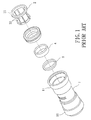
- another conventional water pipe connector is made of plastic and comprises a hollow main body 1 having opposite pipe coupling portions 11, and a pair of clamping components 2.
- Each of the clamping components 2 has a rim portion 21, and a plurality of angularly spaced apart resilient arms 22 extending from the rim portion 21 into a respective one of the pipe coupling portions 11 so as to engage the clamping component 2 to the respective one of the pipe coupling portions 11.
- Each of the resilient arms 22 is provided with a metal positioning member 221 projecting radially and inwardly.
- the resilient arms 22 are loosely disposed around the end segment of the water pipe 100. If the water pipe 100 is pulled away from the pipe coupling portion 11, the clamping component 2 is driven to move along with the water pipe 100 relative to the pipe coupling portion 11 due to friction between the resilient arms 22 and the pipe coupling portion 11. During the movement of the clamping component 2, the resilient arms 22 are urged by an inner wall surface of the pipe coupling port.ion 11 in radial directions, such that the positioning members 221 of the resilient arms 22 abut tightly against the end segment of the water pipe 100 so as to hinder removal of the water pipe 100 from the pipe coupling portion 11. To remove the water pipe 100 from the pipe coupling portion 11, the clamping component. 2 has to be held still relative to the pipe coupling portion 11 while the end segment of the water pipe 100 is pulled out from the pipe coupling portion 11.
- This conventional water pipe connector further has a pair of seal rings 3 and a pair of annular spacers 4.
- Each of the seal rings 3 is an 0-ring, and is disposed in a respective one of the pipe coupling portions 11.
- Each of the annular spacers 4 is disposed in a respective one of the pipe coupling portions 11 between a corresponding one of the seal rings 3 and a corresponding one of the clamping components 2.
- the radial thickness of the rim port.ion 21 of each of the clamping components 2 is too small for a user to hold during the removal of the water pipe 100 from the respective one of the pipe coupling portions 11.
- the removal process of the water pipe 100 from the respective one of the pipe coupling portions 11 is relatively difficult for a beginner without any instructions.
- the object of the present invention is to provide a water pipe connector that facilities connection and removal of a water pipe.
- a water pipe connector of the present invention is adapted for connect.ion to a water pipe and comprises a hollow main body, a clamping component, and a locking collar.
- the main body has a pipe coupling portion that is adapted to be sleeved on one end segment of the water pipe and that has an inner wall surface surrounding an axis, an outer wall surface opposite to the inner wall surface, and a plurality of radial holes formed through the inner and outer wall surfaces and angularly spaced apart from each other relative t.o the axis.
- the clamping component has a rim portion that surrounds the axis, and a plurality of resilient arms that extend from the rim portion parallel to the axis and that are t.o be disposed between the inner wall surface of the pipe coupling portion of the main body and the end segment of the water pipe.
- Each of the resilient arms has an engaging member project.ing through a respective one of the radial holes in the pipe coupling portion of the main body.
- the locking collar is sleeved rotatably on the pipe coupling portion of the main body, has an internal collar surface formed with a plurality of first grooves that are angularly spaced apart from each other relative to the axis, and is rotatable about the axis between an unlocking position, where the engaging members are received respectively in the first grooves in the internal collar surface such that the resilient arms are loosely disposed around the end segment of the water pipe and permit removal of the end segment of the water pipe from the pipe coupling portion of the main body, and a locking position, where the internal collar surface abuts against the engaging members and urges the resilient arms in radial inward directions relative to the axis, thereby enabling the resilient arms to abut tightly against the end segment of the water pipe in the pipe coupling portion so as to arrest removal of the end segment of the water pipe from the pipe coupling portion of the main body.
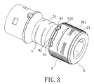
- the first preferred embodiment of a water pipe connector is adapted for connect.ion to a pair of water pipes 100 (only one water pipe 100 is shown in Figure 5 ), and comprises a hollow main body 5 made of rigid plastic, a pair of clamping components 6, a pair of sealing components 7, a pair of spacers 8, and a pair of locking collars 9.
- the main body 5 has an intermediate portion 51 surrounding an axis (L), and a pair of pipe coupling portions 52 extending respectively from two ends of the intermediate portion 51 in opposite directions away from the intermediate portion 51 along the axis (L).
- the intermediate portion 51 has an internal wall surface 510 formed with a plurality of protrusions 511 that are angularly spaced apart from each other relative to the axis (L).
- Each of the pipe coupling portions 52 has an inner wall surface 523, an outer wall surface 524 opposite to the inner wall surface 523 and formed with a pair of stop blocks 522 (only one is visible in Fig.
- each of the clamping components 6 has a rim portion 61 that surrounds the axis (L), and four resilient arms 62 that extend from the rim portion 61 parallel to the axis (L) into a respective one of the pipe coupling portions 52 of the main body 5"
- Each of the resilient arms 62 has an outer arm surface 6202 formed with an engaging member 621 that projects through a respective one of the radial holes 521 in the respective one of the pipe coupling portions 52, and an inner arm surface 6201 opposite t.o the out.er arm surface 6202 and embedded with a positioning member 622.
- each of the positioning members 622 is made of SUS301 metal.
- each of the sealing components 7 is an O-ring surrounding the axis (L), and is disposed in the main body 5 adjacent to a respective one of the pipe coupling portions 52 so as to prevent water leakage.
- Each of the spacers 8 is disposed in a respective one of the pipe coupling portions 52 between the corresponding one of the sealing components 7 and the corresponding one of the clamping components 6, and has one side abutting against the corresponding one of the sealing components 7 for positioning the corresponding one of the sealing components 7 in the main body 5.
- the locking collars 9 are sleeved respectively and rotatably on the pipe coupling portions 52 of the main body 5.
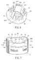
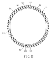
- Each of the locking collars 9 has an internal collar surface 90 formed with four first grooves 93 that are angularly spaced a part from each other relative to the axis (L), and an external collar surface 91 formed with two textured portions 911 that are angularly spaced apart from each other relative to the axis (L).
- Each of the locking collars 9 further has one end formed with a pair of circumferentially extending second grooves 92 to receive the stop blocks 522 of the corresponding one of the pipe coupling portions 52, respectively.
- Each of the second grooves 92 has opposite circumferential ends 920 and is provided with two projections 94 respectively adjacent to the two circumferential ends 920.
- the projections 94 cooperate with the circumferential ends 920 to form angularly opposite first and second groove parts 921, 922.
- each of the locking collars 9 is marked with text "Unlock” and "Lock” respectively adjacent to the first and second groove parts 921, 922.
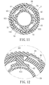
- Each of the locking collars 9 is rotatable about the axis (L) between anunlockingposition (see Figures 9 and 10 ) and a locking position (see Figures 11 and 12 ).
- Each of the first and second groove parts 921, 922 engages removably the corresponding stop block 522 of the corresponding one of the pipe coupling portions 52 so as to retain releasably the locking collar 9 at a desired one of the locking and unlocking positions.
- Each of the first grooves 93 has a groove bottom 931 (see Fig. 8 ) with an inclined segment 95, thereby configuring each of the first grooves 93 with a depth that gradually decreases in an angular direction.
- the end segment of the water pipe 100 is disposed within the resilient arms 62 of the clamping component 6, i.e., the resilient arms 62 are disposed between the inner wall surface 523 of the pipe coupling portion 52 and the end segment of the water pipe 100, and the engaging members 621 of the resilient arms 62 are received respectively in the first grooves 93 in the internal collar surface 90 such that the resilient arms 62 are loosely disposed around the end segment of the water pipe 100.
- the locking collar 9 is rotated about the axis (L) from the unlocking position to the locking position, where the stop blocks 522 are retained in the second groove port.ions 922 of the second grooves 92.
- the internal collar surface 90 abuts against the engaging members 621 and urges the resilient arms 62 in radial inward directions relative to the axis (L), thereby enabling the resilient arms 62 to abut tightly against the end segment of the water pipe 100 in the pipe coupling portion 52 with the positioning members 622 piercing into the end segment of the water pipe 100 so as to arrest removal of the end segment of the water pipe 100 from the pipe coupling portion 52.
- the locking collar 9 can be rotated from the locking position to the unlocking position, such that the engaging members 621 are moved respectively into the first grooves 92 and the resilient arms 62 are released, thereby permitting removal of the end segment of the water pipe 100 from the pipe coupling portion 52.
- the user can easily rotate the locking collar 9 due to the presence of the textured portions 911. Additionally, during rotation of the locking collar 9, the engaging members 621 are moved smoothly and respectively into and out of the first grooves 93, thereby facilitating the use of the water pipe connector of this embodiment.
- the water pipe 100 can be connected to and removed from the water pipe connector of this embodiment by simply rotating the locking collar 9 between the unlocking position and the locking position. Moreover, the text on the locking collar 9 facilitates the user to figure out how to use the water pipe connector of this embodiment.
- the second preferred embodiment of the water pipe connector according to the present invention has a structure similar to that of the first preferred embodiment.
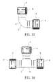
- the main difference between this embodiment and the previous embodiment resides in that the main body 5 is formed in an L-shape.
- the second preferred embodiment has the same advantages as those of the first preferred embodiment.
- the third preferred embodiment of the water pipe connector according to the present invention has a structure similar to that of the first preferred embodiment.
- the main difference between this embodiment and the first preferred embodiment resides in that the main body 5 is formed in a T-shape.
- the third preferred embodiment has the same advantages as those of the first and second preferred embodiments.
- each of the clamping components 6 being formed with four resilient arms 62
- the number of the resilient arms 62 may vary in other embodiments of this invention.
Landscapes
- Engineering & Computer Science (AREA)
- General Engineering & Computer Science (AREA)
- Mechanical Engineering (AREA)
- Quick-Acting Or Multi-Walled Pipe Joints (AREA)
Priority Applications (1)
| Application Number | Priority Date | Filing Date | Title |
|---|---|---|---|
| EP20080101904 EP2093471B1 (de) | 2008-02-22 | 2008-02-22 | Verbindungsstück für Wasserrohre |
Applications Claiming Priority (1)
| Application Number | Priority Date | Filing Date | Title |
|---|---|---|---|
| EP20080101904 EP2093471B1 (de) | 2008-02-22 | 2008-02-22 | Verbindungsstück für Wasserrohre |
Publications (2)
| Publication Number | Publication Date |
|---|---|
| EP2093471A1 true EP2093471A1 (de) | 2009-08-26 |
| EP2093471B1 EP2093471B1 (de) | 2011-07-06 |
Family
ID=39620273
Family Applications (1)
| Application Number | Title | Priority Date | Filing Date |
|---|---|---|---|
| EP20080101904 Ceased EP2093471B1 (de) | 2008-02-22 | 2008-02-22 | Verbindungsstück für Wasserrohre |
Country Status (1)
| Country | Link |
|---|---|
| EP (1) | EP2093471B1 (de) |
Cited By (3)
| Publication number | Priority date | Publication date | Assignee | Title |
|---|---|---|---|---|
| CN103775772A (zh) * | 2014-01-27 | 2014-05-07 | 林新德 | 一种多功能快速接头 |
| KR101404313B1 (ko) | 2007-11-19 | 2014-06-27 | 현대모비스 주식회사 | 회전 잠금 타입 에어 커넥터 앗세이 |
| CN104913144A (zh) * | 2014-03-12 | 2015-09-16 | A·雷蒙德公司 | 具有旋转连接锁的联接装置 |
Citations (5)
| Publication number | Priority date | Publication date | Assignee | Title |
|---|---|---|---|---|
| US4146254A (en) * | 1976-03-31 | 1979-03-27 | Bristol Products, Inc. | Coupler for tubing |
| WO1988002085A1 (en) * | 1986-09-10 | 1988-03-24 | Anthony Roy Robson | Pipe coupling |
| EP0333094A1 (de) * | 1988-03-17 | 1989-09-20 | Lacrex S.A. | Lösbare Verbindungsvorrichtung für Rohre, Schläuche, Stangen oder dergleichen |
| WO2000014445A1 (en) * | 1998-09-02 | 2000-03-16 | Calair Pipe Systems Pty. Ltd. | Connection assembly for coupling to a pipe |
| US20070257488A1 (en) * | 2005-05-09 | 2007-11-08 | Andrew Jimenez | Device and method for making and using a pipe coupling device |
-
2008
- 2008-02-22 EP EP20080101904 patent/EP2093471B1/de not_active Ceased
Patent Citations (5)
| Publication number | Priority date | Publication date | Assignee | Title |
|---|---|---|---|---|
| US4146254A (en) * | 1976-03-31 | 1979-03-27 | Bristol Products, Inc. | Coupler for tubing |
| WO1988002085A1 (en) * | 1986-09-10 | 1988-03-24 | Anthony Roy Robson | Pipe coupling |
| EP0333094A1 (de) * | 1988-03-17 | 1989-09-20 | Lacrex S.A. | Lösbare Verbindungsvorrichtung für Rohre, Schläuche, Stangen oder dergleichen |
| WO2000014445A1 (en) * | 1998-09-02 | 2000-03-16 | Calair Pipe Systems Pty. Ltd. | Connection assembly for coupling to a pipe |
| US20070257488A1 (en) * | 2005-05-09 | 2007-11-08 | Andrew Jimenez | Device and method for making and using a pipe coupling device |
Cited By (6)
| Publication number | Priority date | Publication date | Assignee | Title |
|---|---|---|---|---|
| KR101404313B1 (ko) | 2007-11-19 | 2014-06-27 | 현대모비스 주식회사 | 회전 잠금 타입 에어 커넥터 앗세이 |
| CN103775772A (zh) * | 2014-01-27 | 2014-05-07 | 林新德 | 一种多功能快速接头 |
| CN103775772B (zh) * | 2014-01-27 | 2016-02-17 | 林新德 | 一种多功能快速接头 |
| CN104913144A (zh) * | 2014-03-12 | 2015-09-16 | A·雷蒙德公司 | 具有旋转连接锁的联接装置 |
| WO2015136161A1 (fr) * | 2014-03-12 | 2015-09-17 | A Raymond Et Cie | Dispositif de raccordement avec un verrou de connexion tournant |
| FR3018578A1 (fr) * | 2014-03-12 | 2015-09-18 | Raymond A & Cie | Dispositif de raccordement avec un verrou de connexion tournant |
Also Published As
| Publication number | Publication date |
|---|---|
| EP2093471B1 (de) | 2011-07-06 |
Similar Documents
| Publication | Publication Date | Title |
|---|---|---|
| US7543858B1 (en) | Water pipe connector | |
| NL2024297B1 (en) | A pipe coupling for receiving, holding and releasing a pipe and a method of assembling a pipe coupling | |
| EP0702184B1 (de) | Klemmring | |
| EP1113210B1 (de) | Schnellkupplung mit schwenkbarem Halterungsgehäuse | |
| US20090278346A1 (en) | Connector | |
| IL161657A (en) | Quick release coupling for pipes | |
| RU2548329C2 (ru) | Устройство для отсоединения трубки от сборочного узла трубопровода и способ удаления уплотнения, охватывающего трубку, из корпуса такого устройства | |
| WO2002035130A2 (en) | Bayonet quick coupler | |
| KR20000016764A (ko) | 홈관용 회전방지 신속 연결 커넥터 | |
| US20040093708A1 (en) | Rotatable quick connector stuffer pin | |
| EP2093471A1 (de) | Verbindungsstück für Wasserrohre | |
| JP7593228B2 (ja) | マーキング用治具 | |
| JP2014092222A (ja) | 管継手及び管継手の製造方法 | |
| JP5089487B2 (ja) | 管体の継手構造、これを備えた管継手及びます | |
| CN201162905Y (zh) | 管道接头 | |
| JPH04296291A (ja) | 管継手 | |
| US4412694A (en) | Clamping devices particularly useful as pipe couplings | |
| JP2007292281A (ja) | 管継手 | |
| JPS62101993A (ja) | 管継手 | |
| JP2001141155A (ja) | 管継手 | |
| AU604655B2 (en) | Pipe coupling | |
| JP4066397B2 (ja) | 管体接続方法 | |
| GB2334562A (en) | A connector | |
| JP4032406B2 (ja) | 管継手 | |
| CN101142432A (zh) | 改进的管连接件 |
Legal Events
| Date | Code | Title | Description |
|---|---|---|---|
| PUAI | Public reference made under article 153(3) epc to a published international application that has entered the european phase |
Free format text: ORIGINAL CODE: 0009012 |
|
| AK | Designated contracting states |
Kind code of ref document: A1 Designated state(s): AT BE BG CH CY CZ DE DK EE ES FI FR GB GR HR HU IE IS IT LI LT LU LV MC MT NL NO PL PT RO SE SI SK TR |
|
| AX | Request for extension of the european patent |
Extension state: AL BA MK RS |
|
| 17P | Request for examination filed |
Effective date: 20090831 |
|
| 17Q | First examination report despatched |
Effective date: 20091105 |
|
| AKX | Designation fees paid |
Designated state(s): GB |
|
| REG | Reference to a national code |
Ref country code: DE Ref legal event code: 8566 |
|
| GRAP | Despatch of communication of intention to grant a patent |
Free format text: ORIGINAL CODE: EPIDOSNIGR1 |
|
| GRAS | Grant fee paid |
Free format text: ORIGINAL CODE: EPIDOSNIGR3 |
|
| GRAA | (expected) grant |
Free format text: ORIGINAL CODE: 0009210 |
|
| AK | Designated contracting states |
Kind code of ref document: B1 Designated state(s): GB |
|
| REG | Reference to a national code |
Ref country code: GB Ref legal event code: FG4D |
|
| PLBE | No opposition filed within time limit |
Free format text: ORIGINAL CODE: 0009261 |
|
| STAA | Information on the status of an ep patent application or granted ep patent |
Free format text: STATUS: NO OPPOSITION FILED WITHIN TIME LIMIT |
|
| 26N | No opposition filed |
Effective date: 20120411 |
|
| PGFP | Annual fee paid to national office [announced via postgrant information from national office to epo] |
Ref country code: GB Payment date: 20151221 Year of fee payment: 9 |
|
| GBPC | Gb: european patent ceased through non-payment of renewal fee |
Effective date: 20170222 |
|
| PG25 | Lapsed in a contracting state [announced via postgrant information from national office to epo] |
Ref country code: GB Free format text: LAPSE BECAUSE OF NON-PAYMENT OF DUE FEES Effective date: 20170222 |