EP2093472A2 - Anzeigeset - Google Patents
Anzeigeset Download PDFInfo
- Publication number
- EP2093472A2 EP2093472A2 EP08161780A EP08161780A EP2093472A2 EP 2093472 A2 EP2093472 A2 EP 2093472A2 EP 08161780 A EP08161780 A EP 08161780A EP 08161780 A EP08161780 A EP 08161780A EP 2093472 A2 EP2093472 A2 EP 2093472A2
- Authority
- EP
- European Patent Office
- Prior art keywords
- display
- connector
- display set
- set according
- back plate
- Prior art date
- Legal status (The legal status is an assumption and is not a legal conclusion. Google has not performed a legal analysis and makes no representation as to the accuracy of the status listed.)
- Withdrawn
Links
- 238000012423 maintenance Methods 0.000 description 4
- 238000006073 displacement reaction Methods 0.000 description 2
- 238000003780 insertion Methods 0.000 description 1
- 230000037431 insertion Effects 0.000 description 1
Images


Classifications
-
- F—MECHANICAL ENGINEERING; LIGHTING; HEATING; WEAPONS; BLASTING
- F16—ENGINEERING ELEMENTS AND UNITS; GENERAL MEASURES FOR PRODUCING AND MAINTAINING EFFECTIVE FUNCTIONING OF MACHINES OR INSTALLATIONS; THERMAL INSULATION IN GENERAL
- F16M—FRAMES, CASINGS OR BEDS OF ENGINES, MACHINES OR APPARATUS, NOT SPECIFIC TO ENGINES, MACHINES OR APPARATUS PROVIDED FOR ELSEWHERE; STANDS; SUPPORTS
- F16M11/00—Stands or trestles as supports for apparatus or articles placed thereon ; Stands for scientific apparatus such as gravitational force meters
- F16M11/02—Heads
- F16M11/04—Means for attachment of apparatus; Means allowing adjustment of the apparatus relatively to the stand
- F16M11/06—Means for attachment of apparatus; Means allowing adjustment of the apparatus relatively to the stand allowing pivoting
- F16M11/10—Means for attachment of apparatus; Means allowing adjustment of the apparatus relatively to the stand allowing pivoting around a horizontal axis
-
- F—MECHANICAL ENGINEERING; LIGHTING; HEATING; WEAPONS; BLASTING
- F16—ENGINEERING ELEMENTS AND UNITS; GENERAL MEASURES FOR PRODUCING AND MAINTAINING EFFECTIVE FUNCTIONING OF MACHINES OR INSTALLATIONS; THERMAL INSULATION IN GENERAL
- F16M—FRAMES, CASINGS OR BEDS OF ENGINES, MACHINES OR APPARATUS, NOT SPECIFIC TO ENGINES, MACHINES OR APPARATUS PROVIDED FOR ELSEWHERE; STANDS; SUPPORTS
- F16M11/00—Stands or trestles as supports for apparatus or articles placed thereon ; Stands for scientific apparatus such as gravitational force meters
- F16M11/20—Undercarriages with or without wheels
- F16M11/2007—Undercarriages with or without wheels comprising means allowing pivoting adjustment
- F16M11/2021—Undercarriages with or without wheels comprising means allowing pivoting adjustment around a horizontal axis
Definitions
- the present invention relates to a display set and, more particularly, to a display set including a display and a support unit so that the display can firmly be supported on the support unit and that the display can easily be detached from the support unit for maintenance.
- An ordinary display set includes a display and a support unit pivotally connected to the display.
- a connector is provided on the back of the display.
- the connector is connected to a host through a cable and a convertor.
- a user can view data on the display. If the display is a touch panel, the display can be operated for the input of data to the host.
- the cable is exposed to the user's view.
- the cable may look massy and cause troubles in the installment of the display set.
- the display and the support unit have to be transported together to a service center or repair shop, and this is troublesome and expensive.
- the display and the support unit have to be replaced with a new display and a new support unit together, and this is expensive.
- the present invention is intended to obviate or at least alleviate the problems encountered in prior art.
- a display set includes a support unit, a first connector, a display and a second connector.
- the support unit includes a base, a back support connected to the base and two connective portions formed on the back support.
- the first connector is attached to the back support.
- the display includes a back plate and two connective portions for engagement with the connective portions of the support unit.
- the second connector is attached to the back plate for engagement with the first connector.
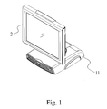
- Fig. 1 is a perspective view of a display set according to the first embodiment of the present invention.
- Fig. 2 is an exploded view of the display set shown in Fig. 1 .
- Fig. 3 is another exploded view of the display set shown in Fig. 1 .
- Fig. 4 is an enlarged view of the display set shown in Fig. 3 .
- Fig. 5 is a perspective view of the display set shown in Fig. 4 .
- Fig. 6 is an exploded view of a display set according to the second embodiment of the present invention.
- the display set includes a support unit 1 and a display 2 so that the display 2 can firmly be supported on the support unit 1 and that the display 2 can easily be detached from the support unit 1 for maintenance, repair or displacement.
- the support unit 1 includes a base 11 and a back support 12 pivotally connected to the base 11.
- the back support 12 is in the form of a rectangular plate.
- the back support 12 includes apertures 121 defined therein.
- the apertures 121 may be countersink holes.
- a connector 13 is attached to the back support 12.
- Two connective portions 14 are formed on the back support 12.
- the connector 13 is located between the connective portions 14.
- the connective portions 14 are in the form of a hook.
- the display 2 includes a back plate 20 that includes an opening 21 defined therein, two connective portions 23 formed at two corners of the opening 21 and screw holes 24.
- the opening 21 is rectangular.
- the connective portions 23 are in the form of a tab.
- the display 2 may be a touch panel or include keys or buttons so that it is operable for the input of data into a host connected to the display 2.
- the back support 12 is inserted through the opening 21. Then, the back plate 20 is lowered onto the back support 12 so that the connective portions 23 of the back plate 20 are engaged with the connective portions 14 of the back support 12. That is, the tabs 23 are hooked on the hooks 14.
- the connector 22 is engaged with the connector 13 simultaneously.
- the engagement of the connector 22 with the connector 13 may be the contact between pads or the insertion of a plug or card into a socket or slot.
- Threaded bolts 3 are driven into the screw holes 24 through the apertures 121. It requires a screwdriver to drive the threaded bolts 3.
- FIG. 6 there is shown a display set according to a second embodiment of the present invention.
- the second embodiment is like the first embodiment except including threaded bolts 4 instead of the threaded bolts 3.
- Each of the threaded bolts 4 is formed with a knob operable by bare hands.
Landscapes
- Engineering & Computer Science (AREA)
- General Engineering & Computer Science (AREA)
- Mechanical Engineering (AREA)
- Devices For Indicating Variable Information By Combining Individual Elements (AREA)
Applications Claiming Priority (1)
| Application Number | Priority Date | Filing Date | Title |
|---|---|---|---|
| TW097203033U TWM342009U (en) | 2008-02-21 | 2008-02-21 | Connection structure of display device |
Publications (2)
| Publication Number | Publication Date |
|---|---|
| EP2093472A2 true EP2093472A2 (de) | 2009-08-26 |
| EP2093472A3 EP2093472A3 (de) | 2010-09-22 |
Family
ID=40568345
Family Applications (1)
| Application Number | Title | Priority Date | Filing Date |
|---|---|---|---|
| EP08161780A Withdrawn EP2093472A3 (de) | 2008-02-21 | 2008-08-05 | Anzeigeset |
Country Status (3)
| Country | Link |
|---|---|
| US (1) | US20090225504A1 (de) |
| EP (1) | EP2093472A3 (de) |
| TW (1) | TWM342009U (de) |
Families Citing this family (7)
| Publication number | Priority date | Publication date | Assignee | Title |
|---|---|---|---|---|
| TWI381729B (zh) * | 2009-07-03 | 2013-01-01 | Au Optronics Corp | 顯示裝置 |
| JP2011180237A (ja) * | 2010-02-26 | 2011-09-15 | Hitachi Consumer Electronics Co Ltd | 映像表示装置 |
| TWI482495B (zh) * | 2012-04-17 | 2015-04-21 | Wistron Corp | 可限制樞轉功能的顯示器 |
| WO2017073872A1 (en) * | 2015-10-26 | 2017-05-04 | Lg Electronics Inc. | Display device |
| TWM525473U (zh) * | 2016-03-08 | 2016-07-11 | 揚昇照明股份有限公司 | 電腦裝置 |
| US9888594B1 (en) * | 2016-09-30 | 2018-02-06 | Hewlett Packard Enterprise Development Lp | Devices including a cavity region to house ports |
| CN112198928B (zh) * | 2020-09-30 | 2023-05-02 | 联想(北京)有限公司 | 一种电子设备 |
Family Cites Families (15)
| Publication number | Priority date | Publication date | Assignee | Title |
|---|---|---|---|---|
| US6702604B1 (en) * | 1999-08-23 | 2004-03-09 | Jerry Moscovitch | Universal quick connector apparatus for an LCD monitor |
| KR100611966B1 (ko) * | 2000-05-18 | 2006-08-11 | 삼성전자주식회사 | 전자제품의 디스플레이 결합 구조체 |
| TW495129U (en) * | 2000-08-07 | 2002-07-11 | Chuntex Electronic Co Ltd | Structure for liquid crystal display |
| US6512670B1 (en) * | 2000-10-05 | 2003-01-28 | International Business Machines Corporation | Detachable displays or portable devices |
| US6400560B1 (en) * | 2000-11-08 | 2002-06-04 | Yue-Hui Chian | Engaging device for a computer screen in a car |
| US6935883B2 (en) * | 2002-04-24 | 2005-08-30 | Innovative Office Products, Inc. | Quick interconnection system for electronic devices |
| KR100770982B1 (ko) * | 2003-02-21 | 2007-10-30 | 삼성전자주식회사 | 디스플레이 장치 |
| KR100770986B1 (ko) * | 2003-08-04 | 2007-10-30 | 삼성전자주식회사 | 타블렛 모니터 |
| TWI225979B (en) * | 2003-09-25 | 2005-01-01 | Aopen Inc | Computer with multiple operation modes |
| TWI230015B (en) * | 2003-11-20 | 2005-03-21 | Benq Corp | Display set |
| JP2005221823A (ja) * | 2004-02-06 | 2005-08-18 | Toshiba Corp | ディスプレイ装置 |
| JP2006091713A (ja) * | 2004-09-27 | 2006-04-06 | Toshiba Corp | ディスプレイ装置 |
| US7193843B2 (en) * | 2005-04-19 | 2007-03-20 | Amtran Technology Co., Ltd. | Display device with a bracket covering |
| US7361046B2 (en) * | 2005-07-01 | 2008-04-22 | Hewlett-Packard Development Company, L.P. | Display assembly |
| JP3116087U (ja) * | 2005-08-25 | 2005-11-24 | 船井電機株式会社 | 液晶テレビジョン |
-
2008
- 2008-02-21 TW TW097203033U patent/TWM342009U/zh not_active IP Right Cessation
- 2008-07-31 US US12/183,938 patent/US20090225504A1/en not_active Abandoned
- 2008-08-05 EP EP08161780A patent/EP2093472A3/de not_active Withdrawn
Also Published As
| Publication number | Publication date |
|---|---|
| US20090225504A1 (en) | 2009-09-10 |
| TWM342009U (en) | 2008-10-01 |
| EP2093472A3 (de) | 2010-09-22 |
Similar Documents
| Publication | Publication Date | Title |
|---|---|---|
| EP2093472A2 (de) | Anzeigeset | |
| US8246301B2 (en) | Fan assembly | |
| US7672126B2 (en) | Mounting apparatus for fan | |
| US7233486B2 (en) | Computer system having interchangeable LCDs | |
| US6909598B2 (en) | Computer device configured for use in different modes | |
| US7699582B2 (en) | Fan module | |
| CN101840255B (zh) | 硬盘固定机构及具有该硬盘固定机构的电子装置 | |
| CN101847037B (zh) | 硬盘固定机构及具有该硬盘固定机构的电子装置 | |
| CN201628898U (zh) | 扩充卡固定装置 | |
| CN103163970A (zh) | 电子装置壳体 | |
| US6859355B2 (en) | Electronic apparatus with replaceable touch control module | |
| US20050157454A1 (en) | Connection port module | |
| CN101907907A (zh) | 电子装置 | |
| US7237854B2 (en) | Computer enclosure incorporating mounting apparatus for disk drives | |
| JP2007293913A (ja) | 液晶ディスプレーの背面に簡易コンピュータをマウントしたパソコン及び液晶ディスプレー付パソコンを組み上げる方法 | |
| US7758308B2 (en) | Mounting apparatus for fan | |
| US20040223298A1 (en) | Computer enclosure with power supply bracket | |
| CN102869216B (zh) | 用来固定键盘的键盘固定结构以及可携式电子装置 | |
| US8824157B2 (en) | Mounting apparatus for expansion cards | |
| US20050111169A1 (en) | Mounting apparatus for power supply | |
| CN101847035B (zh) | 硬盘固定机构及具有该硬盘固定机构的电子装置 | |
| US6731508B2 (en) | Computer enclosure with disk drive bracket | |
| CN1859830B (zh) | 电子设备机壳 | |
| TW201345378A (zh) | 擴充卡固定裝置 | |
| JP2007102746A (ja) | 液晶ディスプレーの背面に簡易コンピュータをマウントしたパソコン及び液晶ディスプレー付パソコンを組み上げる方法 |
Legal Events
| Date | Code | Title | Description |
|---|---|---|---|
| PUAI | Public reference made under article 153(3) epc to a published international application that has entered the european phase |
Free format text: ORIGINAL CODE: 0009012 |
|
| AK | Designated contracting states |
Kind code of ref document: A2 Designated state(s): AT BE BG CH CY CZ DE DK EE ES FI FR GB GR HR HU IE IS IT LI LT LU LV MC MT NL NO PL PT RO SE SI SK TR |
|
| AX | Request for extension of the european patent |
Extension state: AL BA MK RS |
|
| PUAL | Search report despatched |
Free format text: ORIGINAL CODE: 0009013 |
|
| RTI1 | Title (correction) |
Free format text: DISPLAY SET |
|
| AK | Designated contracting states |
Kind code of ref document: A3 Designated state(s): AT BE BG CH CY CZ DE DK EE ES FI FR GB GR HR HU IE IS IT LI LT LU LV MC MT NL NO PL PT RO SE SI SK TR |
|
| AX | Request for extension of the european patent |
Extension state: AL BA MK RS |
|
| RIC1 | Information provided on ipc code assigned before grant |
Ipc: F16M 11/04 20060101ALI20100816BHEP Ipc: F16M 11/10 20060101AFI20090508BHEP |
|
| AKY | No designation fees paid | ||
| STAA | Information on the status of an ep patent application or granted ep patent |
Free format text: STATUS: THE APPLICATION IS DEEMED TO BE WITHDRAWN |
|
| 18D | Application deemed to be withdrawn |
Effective date: 20110323 |