EP2093475B1 - Procédé de remplissage de compresseur et appareil - Google Patents
Procédé de remplissage de compresseur et appareil Download PDFInfo
- Publication number
- EP2093475B1 EP2093475B1 EP09153260.6A EP09153260A EP2093475B1 EP 2093475 B1 EP2093475 B1 EP 2093475B1 EP 09153260 A EP09153260 A EP 09153260A EP 2093475 B1 EP2093475 B1 EP 2093475B1
- Authority
- EP
- European Patent Office
- Prior art keywords
- gas
- vessel
- rate
- temperature
- pressure
- Prior art date
- Legal status (The legal status is an assumption and is not a legal conclusion. Google has not performed a legal analysis and makes no representation as to the accuracy of the status listed.)
- Active
Links
Images

Classifications
-
- F—MECHANICAL ENGINEERING; LIGHTING; HEATING; WEAPONS; BLASTING
- F17—STORING OR DISTRIBUTING GASES OR LIQUIDS
- F17C—VESSELS FOR CONTAINING OR STORING COMPRESSED, LIQUEFIED OR SOLIDIFIED GASES; FIXED-CAPACITY GAS-HOLDERS; FILLING VESSELS WITH, OR DISCHARGING FROM VESSELS, COMPRESSED, LIQUEFIED, OR SOLIDIFIED GASES
- F17C5/00—Methods or apparatus for filling containers with liquefied, solidified, or compressed gases under pressures
- F17C5/06—Methods or apparatus for filling containers with liquefied, solidified, or compressed gases under pressures for filling with compressed gases
-
- F—MECHANICAL ENGINEERING; LIGHTING; HEATING; WEAPONS; BLASTING
- F17—STORING OR DISTRIBUTING GASES OR LIQUIDS
- F17C—VESSELS FOR CONTAINING OR STORING COMPRESSED, LIQUEFIED OR SOLIDIFIED GASES; FIXED-CAPACITY GAS-HOLDERS; FILLING VESSELS WITH, OR DISCHARGING FROM VESSELS, COMPRESSED, LIQUEFIED, OR SOLIDIFIED GASES
- F17C13/00—Details of vessels or of the filling or discharging of vessels
- F17C13/02—Special adaptations of indicating, measuring, or monitoring equipment
- F17C13/025—Special adaptations of indicating, measuring, or monitoring equipment having the pressure as the parameter
-
- F—MECHANICAL ENGINEERING; LIGHTING; HEATING; WEAPONS; BLASTING
- F17—STORING OR DISTRIBUTING GASES OR LIQUIDS
- F17C—VESSELS FOR CONTAINING OR STORING COMPRESSED, LIQUEFIED OR SOLIDIFIED GASES; FIXED-CAPACITY GAS-HOLDERS; FILLING VESSELS WITH, OR DISCHARGING FROM VESSELS, COMPRESSED, LIQUEFIED, OR SOLIDIFIED GASES
- F17C13/00—Details of vessels or of the filling or discharging of vessels
- F17C13/02—Special adaptations of indicating, measuring, or monitoring equipment
- F17C13/026—Special adaptations of indicating, measuring, or monitoring equipment having the temperature as the parameter
-
- F—MECHANICAL ENGINEERING; LIGHTING; HEATING; WEAPONS; BLASTING
- F17—STORING OR DISTRIBUTING GASES OR LIQUIDS
- F17C—VESSELS FOR CONTAINING OR STORING COMPRESSED, LIQUEFIED OR SOLIDIFIED GASES; FIXED-CAPACITY GAS-HOLDERS; FILLING VESSELS WITH, OR DISCHARGING FROM VESSELS, COMPRESSED, LIQUEFIED, OR SOLIDIFIED GASES
- F17C5/00—Methods or apparatus for filling containers with liquefied, solidified, or compressed gases under pressures
- F17C5/002—Automated filling apparatus
- F17C5/007—Automated filling apparatus for individual gas tanks or containers, e.g. in vehicles
-
- F—MECHANICAL ENGINEERING; LIGHTING; HEATING; WEAPONS; BLASTING
- F17—STORING OR DISTRIBUTING GASES OR LIQUIDS
- F17C—VESSELS FOR CONTAINING OR STORING COMPRESSED, LIQUEFIED OR SOLIDIFIED GASES; FIXED-CAPACITY GAS-HOLDERS; FILLING VESSELS WITH, OR DISCHARGING FROM VESSELS, COMPRESSED, LIQUEFIED, OR SOLIDIFIED GASES
- F17C5/00—Methods or apparatus for filling containers with liquefied, solidified, or compressed gases under pressures
- F17C5/02—Methods or apparatus for filling containers with liquefied, solidified, or compressed gases under pressures for filling with liquefied gases
-
- F—MECHANICAL ENGINEERING; LIGHTING; HEATING; WEAPONS; BLASTING
- F17—STORING OR DISTRIBUTING GASES OR LIQUIDS
- F17C—VESSELS FOR CONTAINING OR STORING COMPRESSED, LIQUEFIED OR SOLIDIFIED GASES; FIXED-CAPACITY GAS-HOLDERS; FILLING VESSELS WITH, OR DISCHARGING FROM VESSELS, COMPRESSED, LIQUEFIED, OR SOLIDIFIED GASES
- F17C6/00—Methods and apparatus for filling vessels not under pressure with liquefied or solidified gases
-
- F—MECHANICAL ENGINEERING; LIGHTING; HEATING; WEAPONS; BLASTING
- F17—STORING OR DISTRIBUTING GASES OR LIQUIDS
- F17C—VESSELS FOR CONTAINING OR STORING COMPRESSED, LIQUEFIED OR SOLIDIFIED GASES; FIXED-CAPACITY GAS-HOLDERS; FILLING VESSELS WITH, OR DISCHARGING FROM VESSELS, COMPRESSED, LIQUEFIED, OR SOLIDIFIED GASES
- F17C7/00—Methods or apparatus for discharging liquefied, solidified, or compressed gases from pressure vessels, not covered by another subclass
-
- F—MECHANICAL ENGINEERING; LIGHTING; HEATING; WEAPONS; BLASTING
- F17—STORING OR DISTRIBUTING GASES OR LIQUIDS
- F17C—VESSELS FOR CONTAINING OR STORING COMPRESSED, LIQUEFIED OR SOLIDIFIED GASES; FIXED-CAPACITY GAS-HOLDERS; FILLING VESSELS WITH, OR DISCHARGING FROM VESSELS, COMPRESSED, LIQUEFIED, OR SOLIDIFIED GASES
- F17C9/00—Methods or apparatus for discharging liquefied or solidified gases from vessels not under pressure
-
- F—MECHANICAL ENGINEERING; LIGHTING; HEATING; WEAPONS; BLASTING
- F17—STORING OR DISTRIBUTING GASES OR LIQUIDS
- F17C—VESSELS FOR CONTAINING OR STORING COMPRESSED, LIQUEFIED OR SOLIDIFIED GASES; FIXED-CAPACITY GAS-HOLDERS; FILLING VESSELS WITH, OR DISCHARGING FROM VESSELS, COMPRESSED, LIQUEFIED, OR SOLIDIFIED GASES
- F17C2205/00—Vessel construction, in particular mounting arrangements, attachments or identifications means
- F17C2205/03—Fluid connections, filters, valves, closure means or other attachments
- F17C2205/0302—Fittings, valves, filters, or components in connection with the gas storage device
- F17C2205/0323—Valves
- F17C2205/0326—Valves electrically actuated
-
- F—MECHANICAL ENGINEERING; LIGHTING; HEATING; WEAPONS; BLASTING
- F17—STORING OR DISTRIBUTING GASES OR LIQUIDS
- F17C—VESSELS FOR CONTAINING OR STORING COMPRESSED, LIQUEFIED OR SOLIDIFIED GASES; FIXED-CAPACITY GAS-HOLDERS; FILLING VESSELS WITH, OR DISCHARGING FROM VESSELS, COMPRESSED, LIQUEFIED, OR SOLIDIFIED GASES
- F17C2221/00—Handled fluid, in particular type of fluid
- F17C2221/01—Pure fluids
- F17C2221/012—Hydrogen
-
- F—MECHANICAL ENGINEERING; LIGHTING; HEATING; WEAPONS; BLASTING
- F17—STORING OR DISTRIBUTING GASES OR LIQUIDS
- F17C—VESSELS FOR CONTAINING OR STORING COMPRESSED, LIQUEFIED OR SOLIDIFIED GASES; FIXED-CAPACITY GAS-HOLDERS; FILLING VESSELS WITH, OR DISCHARGING FROM VESSELS, COMPRESSED, LIQUEFIED, OR SOLIDIFIED GASES
- F17C2223/00—Handled fluid before transfer, i.e. state of fluid when stored in the vessel or before transfer from the vessel
- F17C2223/01—Handled fluid before transfer, i.e. state of fluid when stored in the vessel or before transfer from the vessel characterised by the phase
- F17C2223/0107—Single phase
- F17C2223/0123—Single phase gaseous, e.g. CNG, GNC
-
- F—MECHANICAL ENGINEERING; LIGHTING; HEATING; WEAPONS; BLASTING
- F17—STORING OR DISTRIBUTING GASES OR LIQUIDS
- F17C—VESSELS FOR CONTAINING OR STORING COMPRESSED, LIQUEFIED OR SOLIDIFIED GASES; FIXED-CAPACITY GAS-HOLDERS; FILLING VESSELS WITH, OR DISCHARGING FROM VESSELS, COMPRESSED, LIQUEFIED, OR SOLIDIFIED GASES
- F17C2223/00—Handled fluid before transfer, i.e. state of fluid when stored in the vessel or before transfer from the vessel
- F17C2223/01—Handled fluid before transfer, i.e. state of fluid when stored in the vessel or before transfer from the vessel characterised by the phase
- F17C2223/0146—Two-phase
- F17C2223/0153—Liquefied gas, e.g. LPG, GPL
- F17C2223/0161—Liquefied gas, e.g. LPG, GPL cryogenic, e.g. LNG, GNL, PLNG
-
- F—MECHANICAL ENGINEERING; LIGHTING; HEATING; WEAPONS; BLASTING
- F17—STORING OR DISTRIBUTING GASES OR LIQUIDS
- F17C—VESSELS FOR CONTAINING OR STORING COMPRESSED, LIQUEFIED OR SOLIDIFIED GASES; FIXED-CAPACITY GAS-HOLDERS; FILLING VESSELS WITH, OR DISCHARGING FROM VESSELS, COMPRESSED, LIQUEFIED, OR SOLIDIFIED GASES
- F17C2223/00—Handled fluid before transfer, i.e. state of fluid when stored in the vessel or before transfer from the vessel
- F17C2223/03—Handled fluid before transfer, i.e. state of fluid when stored in the vessel or before transfer from the vessel characterised by the pressure level
- F17C2223/033—Small pressure, e.g. for liquefied gas
-
- F—MECHANICAL ENGINEERING; LIGHTING; HEATING; WEAPONS; BLASTING
- F17—STORING OR DISTRIBUTING GASES OR LIQUIDS
- F17C—VESSELS FOR CONTAINING OR STORING COMPRESSED, LIQUEFIED OR SOLIDIFIED GASES; FIXED-CAPACITY GAS-HOLDERS; FILLING VESSELS WITH, OR DISCHARGING FROM VESSELS, COMPRESSED, LIQUEFIED, OR SOLIDIFIED GASES
- F17C2223/00—Handled fluid before transfer, i.e. state of fluid when stored in the vessel or before transfer from the vessel
- F17C2223/03—Handled fluid before transfer, i.e. state of fluid when stored in the vessel or before transfer from the vessel characterised by the pressure level
- F17C2223/035—High pressure (>10 bar)
-
- F—MECHANICAL ENGINEERING; LIGHTING; HEATING; WEAPONS; BLASTING
- F17—STORING OR DISTRIBUTING GASES OR LIQUIDS
- F17C—VESSELS FOR CONTAINING OR STORING COMPRESSED, LIQUEFIED OR SOLIDIFIED GASES; FIXED-CAPACITY GAS-HOLDERS; FILLING VESSELS WITH, OR DISCHARGING FROM VESSELS, COMPRESSED, LIQUEFIED, OR SOLIDIFIED GASES
- F17C2223/00—Handled fluid before transfer, i.e. state of fluid when stored in the vessel or before transfer from the vessel
- F17C2223/04—Handled fluid before transfer, i.e. state of fluid when stored in the vessel or before transfer from the vessel characterised by other properties of handled fluid before transfer
- F17C2223/042—Localisation of the removal point
- F17C2223/046—Localisation of the removal point in the liquid
-
- F—MECHANICAL ENGINEERING; LIGHTING; HEATING; WEAPONS; BLASTING
- F17—STORING OR DISTRIBUTING GASES OR LIQUIDS
- F17C—VESSELS FOR CONTAINING OR STORING COMPRESSED, LIQUEFIED OR SOLIDIFIED GASES; FIXED-CAPACITY GAS-HOLDERS; FILLING VESSELS WITH, OR DISCHARGING FROM VESSELS, COMPRESSED, LIQUEFIED, OR SOLIDIFIED GASES
- F17C2225/00—Handled fluid after transfer, i.e. state of fluid after transfer from the vessel
- F17C2225/01—Handled fluid after transfer, i.e. state of fluid after transfer from the vessel characterised by the phase
- F17C2225/0107—Single phase
- F17C2225/0123—Single phase gaseous, e.g. CNG, GNC
-
- F—MECHANICAL ENGINEERING; LIGHTING; HEATING; WEAPONS; BLASTING
- F17—STORING OR DISTRIBUTING GASES OR LIQUIDS
- F17C—VESSELS FOR CONTAINING OR STORING COMPRESSED, LIQUEFIED OR SOLIDIFIED GASES; FIXED-CAPACITY GAS-HOLDERS; FILLING VESSELS WITH, OR DISCHARGING FROM VESSELS, COMPRESSED, LIQUEFIED, OR SOLIDIFIED GASES
- F17C2225/00—Handled fluid after transfer, i.e. state of fluid after transfer from the vessel
- F17C2225/03—Handled fluid after transfer, i.e. state of fluid after transfer from the vessel characterised by the pressure level
- F17C2225/035—High pressure, i.e. between 10 and 80 bars
-
- F—MECHANICAL ENGINEERING; LIGHTING; HEATING; WEAPONS; BLASTING
- F17—STORING OR DISTRIBUTING GASES OR LIQUIDS
- F17C—VESSELS FOR CONTAINING OR STORING COMPRESSED, LIQUEFIED OR SOLIDIFIED GASES; FIXED-CAPACITY GAS-HOLDERS; FILLING VESSELS WITH, OR DISCHARGING FROM VESSELS, COMPRESSED, LIQUEFIED, OR SOLIDIFIED GASES
- F17C2225/00—Handled fluid after transfer, i.e. state of fluid after transfer from the vessel
- F17C2225/03—Handled fluid after transfer, i.e. state of fluid after transfer from the vessel characterised by the pressure level
- F17C2225/036—Very high pressure, i.e. above 80 bars
-
- F—MECHANICAL ENGINEERING; LIGHTING; HEATING; WEAPONS; BLASTING
- F17—STORING OR DISTRIBUTING GASES OR LIQUIDS
- F17C—VESSELS FOR CONTAINING OR STORING COMPRESSED, LIQUEFIED OR SOLIDIFIED GASES; FIXED-CAPACITY GAS-HOLDERS; FILLING VESSELS WITH, OR DISCHARGING FROM VESSELS, COMPRESSED, LIQUEFIED, OR SOLIDIFIED GASES
- F17C2227/00—Transfer of fluids, i.e. method or means for transferring the fluid; Heat exchange with the fluid
- F17C2227/01—Propulsion of the fluid
- F17C2227/0128—Propulsion of the fluid with pumps or compressors
- F17C2227/0135—Pumps
- F17C2227/0142—Pumps with specified pump type, e.g. piston or impulsive type
-
- F—MECHANICAL ENGINEERING; LIGHTING; HEATING; WEAPONS; BLASTING
- F17—STORING OR DISTRIBUTING GASES OR LIQUIDS
- F17C—VESSELS FOR CONTAINING OR STORING COMPRESSED, LIQUEFIED OR SOLIDIFIED GASES; FIXED-CAPACITY GAS-HOLDERS; FILLING VESSELS WITH, OR DISCHARGING FROM VESSELS, COMPRESSED, LIQUEFIED, OR SOLIDIFIED GASES
- F17C2227/00—Transfer of fluids, i.e. method or means for transferring the fluid; Heat exchange with the fluid
- F17C2227/01—Propulsion of the fluid
- F17C2227/0128—Propulsion of the fluid with pumps or compressors
- F17C2227/0157—Compressors
- F17C2227/0164—Compressors with specified compressor type, e.g. piston or impulsive type
-
- F—MECHANICAL ENGINEERING; LIGHTING; HEATING; WEAPONS; BLASTING
- F17—STORING OR DISTRIBUTING GASES OR LIQUIDS
- F17C—VESSELS FOR CONTAINING OR STORING COMPRESSED, LIQUEFIED OR SOLIDIFIED GASES; FIXED-CAPACITY GAS-HOLDERS; FILLING VESSELS WITH, OR DISCHARGING FROM VESSELS, COMPRESSED, LIQUEFIED, OR SOLIDIFIED GASES
- F17C2227/00—Transfer of fluids, i.e. method or means for transferring the fluid; Heat exchange with the fluid
- F17C2227/03—Heat exchange with the fluid
- F17C2227/0367—Localisation of heat exchange
- F17C2227/0388—Localisation of heat exchange separate
- F17C2227/0393—Localisation of heat exchange separate using a vaporiser
-
- F—MECHANICAL ENGINEERING; LIGHTING; HEATING; WEAPONS; BLASTING
- F17—STORING OR DISTRIBUTING GASES OR LIQUIDS
- F17C—VESSELS FOR CONTAINING OR STORING COMPRESSED, LIQUEFIED OR SOLIDIFIED GASES; FIXED-CAPACITY GAS-HOLDERS; FILLING VESSELS WITH, OR DISCHARGING FROM VESSELS, COMPRESSED, LIQUEFIED, OR SOLIDIFIED GASES
- F17C2250/00—Accessories; Control means; Indicating, measuring or monitoring of parameters
- F17C2250/03—Control means
- F17C2250/032—Control means using computers
-
- F—MECHANICAL ENGINEERING; LIGHTING; HEATING; WEAPONS; BLASTING
- F17—STORING OR DISTRIBUTING GASES OR LIQUIDS
- F17C—VESSELS FOR CONTAINING OR STORING COMPRESSED, LIQUEFIED OR SOLIDIFIED GASES; FIXED-CAPACITY GAS-HOLDERS; FILLING VESSELS WITH, OR DISCHARGING FROM VESSELS, COMPRESSED, LIQUEFIED, OR SOLIDIFIED GASES
- F17C2250/00—Accessories; Control means; Indicating, measuring or monitoring of parameters
- F17C2250/04—Indicating or measuring of parameters as input values
- F17C2250/0404—Parameters indicated or measured
- F17C2250/043—Pressure
-
- F—MECHANICAL ENGINEERING; LIGHTING; HEATING; WEAPONS; BLASTING
- F17—STORING OR DISTRIBUTING GASES OR LIQUIDS
- F17C—VESSELS FOR CONTAINING OR STORING COMPRESSED, LIQUEFIED OR SOLIDIFIED GASES; FIXED-CAPACITY GAS-HOLDERS; FILLING VESSELS WITH, OR DISCHARGING FROM VESSELS, COMPRESSED, LIQUEFIED, OR SOLIDIFIED GASES
- F17C2250/00—Accessories; Control means; Indicating, measuring or monitoring of parameters
- F17C2250/04—Indicating or measuring of parameters as input values
- F17C2250/0404—Parameters indicated or measured
- F17C2250/0439—Temperature
-
- F—MECHANICAL ENGINEERING; LIGHTING; HEATING; WEAPONS; BLASTING
- F17—STORING OR DISTRIBUTING GASES OR LIQUIDS
- F17C—VESSELS FOR CONTAINING OR STORING COMPRESSED, LIQUEFIED OR SOLIDIFIED GASES; FIXED-CAPACITY GAS-HOLDERS; FILLING VESSELS WITH, OR DISCHARGING FROM VESSELS, COMPRESSED, LIQUEFIED, OR SOLIDIFIED GASES
- F17C2250/00—Accessories; Control means; Indicating, measuring or monitoring of parameters
- F17C2250/04—Indicating or measuring of parameters as input values
- F17C2250/0486—Indicating or measuring characterised by the location
- F17C2250/0491—Parameters measured at or inside the vessel
-
- F—MECHANICAL ENGINEERING; LIGHTING; HEATING; WEAPONS; BLASTING
- F17—STORING OR DISTRIBUTING GASES OR LIQUIDS
- F17C—VESSELS FOR CONTAINING OR STORING COMPRESSED, LIQUEFIED OR SOLIDIFIED GASES; FIXED-CAPACITY GAS-HOLDERS; FILLING VESSELS WITH, OR DISCHARGING FROM VESSELS, COMPRESSED, LIQUEFIED, OR SOLIDIFIED GASES
- F17C2250/00—Accessories; Control means; Indicating, measuring or monitoring of parameters
- F17C2250/06—Controlling or regulating of parameters as output values
- F17C2250/0605—Parameters
- F17C2250/0636—Flow or movement of content
-
- F—MECHANICAL ENGINEERING; LIGHTING; HEATING; WEAPONS; BLASTING
- F17—STORING OR DISTRIBUTING GASES OR LIQUIDS
- F17C—VESSELS FOR CONTAINING OR STORING COMPRESSED, LIQUEFIED OR SOLIDIFIED GASES; FIXED-CAPACITY GAS-HOLDERS; FILLING VESSELS WITH, OR DISCHARGING FROM VESSELS, COMPRESSED, LIQUEFIED, OR SOLIDIFIED GASES
- F17C2260/00—Purposes of gas storage and gas handling
- F17C2260/02—Improving properties related to fluid or fluid transfer
- F17C2260/023—Avoiding overheating
-
- F—MECHANICAL ENGINEERING; LIGHTING; HEATING; WEAPONS; BLASTING
- F17—STORING OR DISTRIBUTING GASES OR LIQUIDS
- F17C—VESSELS FOR CONTAINING OR STORING COMPRESSED, LIQUEFIED OR SOLIDIFIED GASES; FIXED-CAPACITY GAS-HOLDERS; FILLING VESSELS WITH, OR DISCHARGING FROM VESSELS, COMPRESSED, LIQUEFIED, OR SOLIDIFIED GASES
- F17C2265/00—Effects achieved by gas storage or gas handling
- F17C2265/06—Fluid distribution
- F17C2265/065—Fluid distribution for refuelling vehicle fuel tanks
-
- F—MECHANICAL ENGINEERING; LIGHTING; HEATING; WEAPONS; BLASTING
- F17—STORING OR DISTRIBUTING GASES OR LIQUIDS
- F17C—VESSELS FOR CONTAINING OR STORING COMPRESSED, LIQUEFIED OR SOLIDIFIED GASES; FIXED-CAPACITY GAS-HOLDERS; FILLING VESSELS WITH, OR DISCHARGING FROM VESSELS, COMPRESSED, LIQUEFIED, OR SOLIDIFIED GASES
- F17C2270/00—Applications
- F17C2270/01—Applications for fluid transport or storage
- F17C2270/0134—Applications for fluid transport or storage placed above the ground
- F17C2270/0139—Fuel stations
-
- F—MECHANICAL ENGINEERING; LIGHTING; HEATING; WEAPONS; BLASTING
- F17—STORING OR DISTRIBUTING GASES OR LIQUIDS
- F17C—VESSELS FOR CONTAINING OR STORING COMPRESSED, LIQUEFIED OR SOLIDIFIED GASES; FIXED-CAPACITY GAS-HOLDERS; FILLING VESSELS WITH, OR DISCHARGING FROM VESSELS, COMPRESSED, LIQUEFIED, OR SOLIDIFIED GASES
- F17C2270/00—Applications
- F17C2270/01—Applications for fluid transport or storage
- F17C2270/0165—Applications for fluid transport or storage on the road
- F17C2270/0168—Applications for fluid transport or storage on the road by vehicles
- F17C2270/0171—Trucks
-
- F—MECHANICAL ENGINEERING; LIGHTING; HEATING; WEAPONS; BLASTING
- F17—STORING OR DISTRIBUTING GASES OR LIQUIDS
- F17C—VESSELS FOR CONTAINING OR STORING COMPRESSED, LIQUEFIED OR SOLIDIFIED GASES; FIXED-CAPACITY GAS-HOLDERS; FILLING VESSELS WITH, OR DISCHARGING FROM VESSELS, COMPRESSED, LIQUEFIED, OR SOLIDIFIED GASES
- F17C2270/00—Applications
- F17C2270/01—Applications for fluid transport or storage
- F17C2270/0165—Applications for fluid transport or storage on the road
- F17C2270/0168—Applications for fluid transport or storage on the road by vehicles
- F17C2270/0176—Buses
-
- F—MECHANICAL ENGINEERING; LIGHTING; HEATING; WEAPONS; BLASTING
- F17—STORING OR DISTRIBUTING GASES OR LIQUIDS
- F17C—VESSELS FOR CONTAINING OR STORING COMPRESSED, LIQUEFIED OR SOLIDIFIED GASES; FIXED-CAPACITY GAS-HOLDERS; FILLING VESSELS WITH, OR DISCHARGING FROM VESSELS, COMPRESSED, LIQUEFIED, OR SOLIDIFIED GASES
- F17C2270/00—Applications
- F17C2270/01—Applications for fluid transport or storage
- F17C2270/0165—Applications for fluid transport or storage on the road
- F17C2270/0168—Applications for fluid transport or storage on the road by vehicles
- F17C2270/0178—Cars
-
- Y—GENERAL TAGGING OF NEW TECHNOLOGICAL DEVELOPMENTS; GENERAL TAGGING OF CROSS-SECTIONAL TECHNOLOGIES SPANNING OVER SEVERAL SECTIONS OF THE IPC; TECHNICAL SUBJECTS COVERED BY FORMER USPC CROSS-REFERENCE ART COLLECTIONS [XRACs] AND DIGESTS
- Y02—TECHNOLOGIES OR APPLICATIONS FOR MITIGATION OR ADAPTATION AGAINST CLIMATE CHANGE
- Y02E—REDUCTION OF GREENHOUSE GAS [GHG] EMISSIONS, RELATED TO ENERGY GENERATION, TRANSMISSION OR DISTRIBUTION
- Y02E60/00—Enabling technologies; Technologies with a potential or indirect contribution to GHG emissions mitigation
- Y02E60/30—Hydrogen technology
- Y02E60/32—Hydrogen storage
Definitions
- This invention relates to an apparatus and a method for filling a vessel, such as a fuel tank, with a compressed gas, such as hydrogen, safely over a minimum period of time without overheating the vessel.
- a vessel such as a fuel tank
- Gaseous hydrogen is expected to supplant liquid hydrocarbon fuels, such as gasoline and diesel, as the fuel of choice for automobiles, trucks and buses due to its obvious environmental advantage. Hydrogen burns cleanly and does not produce greenhouse gases such as CO and CO 2 as a combustion by-product.
- EP 0516580A1 discloses a refueling appliance for refueling a gas fuel tank 13 having a compressor 1 which can be driven via an electric motor 3.
- the compressor 1 is coupled to a fuel tank via conduit 12 and a source 8 of gas fuel via conduit 7.
- the source of gas fuel is a natural gas line.
- the refueling appliance comprises a differential pressure switch 17 and a pressure sensor 24 which are connected via electrical signal lines 30 and 31 respectively to a control appliance 32.
- the present invention concerns a method of filling a vessel (12) with a gas at a predetermined rise rate of gas pressure, said method comprising:
- Measuring comprises measuring the instantaneous gas pressure within the vessel, the gas pressure within the vessel being used to adjust the flow rate to achieve the predetermined rise rate of the gas pressure within the vessel.
- measuring step (b) may also comprises measuring the instantaneous gas temperature within the vessel, the gas temperature within the vessel being used to adjust the flow rate to achieve the predetermined rise rate of the gas pressure within the vessel.
- measuring step (b) comprises measuring the ambient temperature surrounding the vessel, the ambient temperature being used to adjust the flow rate to achieve the predetermined rise rate of the gas pressure within the vessel.
- measuring step (b) comprises measuring the temperature of the gas before compressing the gas into the vessel, the temperature of the gas before the compressing into the vessel being used to adjust the flow rate to achieve the predetermined rise rate of the gas pressure within the vessel.
- the invention also encompasses an apparatus for filling a vessel with a gas.
- the apparatus comprises a source of the gas and a compressing means for compressing the gas.
- the compressing means has a variable mass flow rate and an inlet and an outlet.
- a first conduit connects the source and the inlet, and a second conduit connects the outlet and the vessel.
- a controller controls the mass flow rate of the compressing means.
- a transducer measures the value of gas pressure within the vessel.
- a transducer may further measures the value of a parameter selected from the group consisting of gas temperature, ambient temperature and combinations thereof.
- the controller receives electrical signals from the transducer and uses the electrical signals to control the mass flow rate of the compressing means to fill the vessel from the source.
- FIG. 1 shows, in schematic form, an apparatus 10 for filling a vessel 12 with a gas 14.
- Apparatus 10 comprises a source 16 of gas 14.
- the gas 14 may be stored as a liquid 15 or as the gas 14 at the source.
- Source 16 is connected in fluid communication with the inlet 18 of a fluid compressing means 20 by a conduit 22.
- the fluid compressing means 20 may comprise a variable mass flow rate pump or compressor as appropriate depending upon whether a liquid or gaseous fluid is supplied to the inlet 18.
- a variable mass flow rate compressor or pump may be used for liquids, whereas a variable mass flow rate compressor is used for gas fed to the inlet.
- the mass flow rate for these pumps and compressors is varied typically by varying the speed of the pump or compressor.
- Flow of fluid (liquid 15 or gas 14) from source 16 to the compressing means inlet 18 is controlled by a valve 24 positioned within the conduit 22 between the source and the compressing means.
- Compressing means 20 has an outlet 26 which may be connected in fluid communication with the vessel 12 using a conduit 28. If liquid 15 is supplied from the compressing means 20 to the conduit 28 then a vaporizer 29 is in fluid communication with the conduit 28 to change the state of the fluid to the gas 14.
- the conduit 28 has a coupling 30 which is sealingly connectable to and disconnectable from the vessel 12.
- Flow of liquid 15 or gas 14 from the compressing means outlet 26 may be controlled by a valve 32 in the conduit 28.
- the source 16 may also be connected to the vessel directly using a conduit 34.
- a valve 36 in the conduit 34 is used to control flow of gas 14 directly from the source 16 to the vessel 12. Note that conduit 34 may share the coupling 30 with conduit 28 for connection to the vessel 12.
- the apparatus comprises one or more pressure transducers and may comprise one or more temperature transducers, for example, pressure transducer 38 which measures the gas pressure supplied from the source in conduit 22, pressure transducers 40 and 42, which measure the gas pressure at the inlet 18 and outlet 26, respectively, of the compressing means 20, and pressure transducer 44, which measures the gas pressure within conduits 28 and 34 as delivered to the vessel 12 and is at least present in the apparatus.
- Temperature transducers include transducer 46, which measures the ambient temperature surrounding the vessel 12, transducer 48, which measures the temperature of the gas within the vessel 12, and transducer 50, which measures the temperature of the gas within conduits 28 and 34 before entering vessel 12.
- Each pressure transducer 38, 40, 42 and 44 generates electrical signals indicative of pressure at their respective measurement points.
- the temperature transducers 46, 48 and 50 generate electrical signals indicative of the temperature at their respective measurement points.
- the transducers need not be located exactly at the point where the measurement is desired, as it is possible to infer the temperature or pressure at a location, for example, within the vessel 12, by measuring the temperature on the outside surface of the vessel, and the pressure in a conduit hydraulically connected to the vessel. It is further understood that every transducer disclosed herein is not necessarily used simultaneously in the apparatus, the exemplary embodiment shown in Figure 1 illustrates several possible configurations which may have a single transducer or combinations of transducers.
- the signals generated by the transducers are transmitted to a controller 52 which is also in communication with valves 24, 32 and 36 as well as the variable flow rate compressing means 20.
- the controller 52 which may be for example, a programmable logic controller or other microprocessor based device, runs resident software and uses the signals from the transducers in a feed-back loop to open and close the valves and vary the flow rate of the compressing means (for example by varying its speed) according to an algorithm to adjust the flow rate of gas 14 to the vessel 12 to increase the gas pressure within the vessel at a predetermined rate of change as described below.
- a user interface 54 for example, a keyboard and display monitor, provides communication with the controller permitting the apparatus 10 to be operated to dispense gas from the source to the vessel.
- the apparatus 10 may serve as a fueling station for dispensing hydrogen fuel to vehicles, the fuel tank comprising the vessel 12.
- Vehicle tanks have a maximum allowed pressure of about 875 bar. It is desired to maintain the vessel at or below 85°C to avoid overheating.
- the gas source 16 comprises a liquid hydrogen storage tank having a capacity between about 5,700 liters and about 171,000 liters. Hydrogen gas is stored in the reservoir at a pressure between about 0 and about 90 MPa.
- the gas source 16 may comprise, for example, a steam methane reformer, an electrolysis apparatus or a hydrogen pipeline.
- the valves may be pneumatic plug valves which are actuatable by the controller.
- the pressure transducers may be, for example, piezo-electric transducers.
- the temperature transducers may comprise thermistors.
- the compressing means operates to provide a mass flow rate variable between about 0.1 and about 10 kg/min.
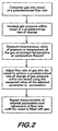
- Figure 2 provides a flow chart describing an exemplary mode of operation of the apparatus.
- the exemplary mode described herein assumes the gas 14 is supplied from the source 16. Operation wherein the liquid 15 is supplied from the source is substantially similar to the operation described herein and is not described separately, it being understood that the liquid 15 is eventually vaporized before entering vessel 12.
- the coupling 30 is connected to the vessel 12 and a user activates the apparatus with the interface 54.
- Valve 24 is opened providing gas 14 from the source 16 to the compressing means 20.
- Valve 32 is opened providing gas from the compressing means to the vessel 12.
- the compressing means is started and begins compressing gas 14 into vessel 12 at a predetermined flow rate.
- One or more of the aforementioned transducers, but at least transducer 44 measures the instantaneous value of a selected parameter or paramters (pressure or temperature of the gas, or ambient temperature, or combinations thereof) and generates signals indicative of that value or values.
- the signals are transmitted to the controller 52.
- Signal transmission symbolized by the dotted lines in Figure 1 , may be over wires or wirelessly via a radio frequency link.
- the controller uses the measured values of the parameter or parameters to adjust the compressing means' flow rate (for example, by adjusting its speed of operation) to increase the gas pressure within the vessel at a predetermined rate of change, known as the pressure rise rate, which will fill the vessel in a predetermined amount of time without overheating the vessel.
- the parameter measurements are repeated periodically so that the compressing means' flow rate may be continuously adjusted to take into account the changing pressure within the vessel.
- the controller halts the flow of gas to the vessel once it is filled to capacity.
- the valves 24 and 32 are closed and the coupling is disconnected from the vessel.
- the controller may use various parameters and associated algorithms to achieve the desired gas pressure change rate within the vessel 12.
- the gas pressure may be increased at a constant rate.
- the constant increase rate may range between about 2.5MPa/min and about 35 MPa/min.
- the gas pressure in the vessel increases at an increasing rate. There is also the possibility to increase the pressure at a decreasing rate.
- the controller receives pressure measurements from the pressure transducer 44 which measures values of the gas pressure within the vessel 12.
- the compressing means' flow rate may be measured as a mass flow rate in grams/second and the pressure rise rates may be measured in MPa/min. This yields the units associated with the gain K as grams/second per MPa/min for consistency of the functional relationship.
- the gain K will be specific to a particular apparatus and is determined experimentally consistent with control system practices.
- the controller may also receive temperature measurements from the temperature transducer 48 which measures values of the gas temperature within the vessel 12.
- the controller adjusts the compressing means' flow rate using the gas temperature values, for example based upon the functional relation:
- pressure rise rate (85-gas temperature)x0.555.
- the controller may also receive temperature measurements from the temperature transducer 46 which measures ambient temperature values surrounding the vessel 12.
- the controller adjusts the compressing means' flow rate using the ambient temperature values, for example based upon the functional relation:
- the controller may also receive temperature measurements from the temperature transducer 50 which measures values of the gas temperature before it is compressed into the vessel 12.
- the controller adjusts the compressing means' flow rate using the gas temperature values, for example based upon the functional relation:
- the gas source 16 comprises a reservoir of sufficient pressure and capacity, for example at a pressure between about 15 MPa and about 70 MPa and a capacity between about 40 liters and about 1,000 liters
- the controller 52 first opens the valve 36 allowing gas to flow from the source 16 directly to the vessel 12 until the gas pressure within the vessel equalizes with the gas pressure of the source.
- the controller then closes valve 36 and opens the valves and starts the compressing means as described above to fill the vessel by increasing the gas pressure at a predetermined rate of change.
- the method and apparatus according to the invention allows gas vessels to be filled safely and in a reasonable period of time without the fear of overheating and its consequences.
Landscapes
- Engineering & Computer Science (AREA)
- Mechanical Engineering (AREA)
- General Engineering & Computer Science (AREA)
- Filling Or Discharging Of Gas Storage Vessels (AREA)
Claims (16)
- Procédé de remplissage d'un récipient (12) avec du gaz à une vitesse d'augmentation prédéterminée de la pression de gaz, ledit procédé comprenant:(a) comprimer ledit gaz dans ledit récipient (12) en utilisant des moyens de compression (20);(b) mesurer une valeur instantanée de pression de gaz à l'intérieur du récipient (12);(c) générer des signaux électriques indicatifs de la valeur instantanée de la pression de gaz à l'intérieur du récipient (12);(d) transmettre les signaux électriques à un dispositif de commande (52),
caractérisé par la compression dudit gaz à l'étape (a) dans ledit récipient (12) à un débit prédéterminé en utilisant les moyens de compression (20) présentant un débit massique variable;(e) utiliser les signaux électriques pour faire varier le débit des moyens de compression (20) suivant un algorithme utilisé par le dispositif de commande (52) pour régler ledit débit dudit gaz dans ledit récipient (12) pour atteindre ladite vitesse d'augmentation prédéterminée de ladite pression de gaz; et(f) répéter les étapes (b) à (e) jusqu'à ce que le récipient (12) soit rempli avec ledit gaz. - Procédé selon la revendication 1, dans lequel ladite vitesse d'augmentation prédéterminée présente une vitesse de variation constante.
- Procédé selon la revendication 1, dans lequel ladite vitesse d'augmentation prédéterminée présente une vitesse de variation qui augmente à une vitesse croissante.
- Procédé selon la revendication 1, dans lequel ladite vitesse d'augmentation prédéterminée présente une vitesse de variation qui augmente à une vitesse décroissante.
- Procédé selon la revendication 1, dans lequel ledit débit est établi suivant la relation: débit des moyens de compression(n+1) = débit des moyens de compression(n) + (vitesse d'augmentation de pression cible - vitesse d'augmentation de pression mesuré) x K, dans lequel K est un gain pour le dispositif de commande (52).
- Procédé selon l'une quelconque des revendications précédentes, comprenant en outre la mesure de la température du gaz instantanée à l'intérieur dudit récipient (12), ladite température du gaz à l'intérieur dudit récipient (12) étant utilisée pour régler ledit débit pour atteindre ladite vitesse d'augmentation prédéterminée de ladite pression de gaz à l'intérieur dudit récipient (12).
- Procédé selon la revendication 6, dans lequel ladite vitesse d'augmentation prédéterminée de ladite pression de gaz à l'intérieur dudit récipient (12) est maintenue à 35 MPa/minute lorsque ladite température du gaz à l'intérieur dudit récipient (12) est inférieure à 65,6°C, et lorsque ladite température du gaz dans ledit récipient (12) dépasse 65,6°C ladite vitesse d'augmentation de pression est réduit suivant la formule: vitesse d'augmentation de pression = (85 [°C] -température du gaz [°C] x 0,555 [MPa/minute °C] .
- Procédé selon l'une quelconque des revendications précédentes, comprenant en outre la mesure de la température ambiante autour dudit récipient (12), ladite température ambiante étant utilisée pour régler ledit débit pour atteindre ladite vitesse d'augmentation prédéterminée de ladite pression de gaz à l'intérieur dudit récipient (12).
- Procédé selon la revendication 8, dans lequel, si ladite température ambiante est inférieure à 15°C, alors la vitesse d'augmentation prédéterminée est maintenue à 10 MPa/minute, et si ladite température ambiante est supérieure à 15°C et inférieure à 30°C, alors la vitesse d'augmentation prédéterminée est maintenue à 7,5 MPa/minute, et si ladite température ambiante est supérieure à 30°C, alors ladite vitesse d'augmentation prédéterminée est maintenue à 5 MPa/minute.
- Procédé selon l'une quelconque des revendications précédentes, comprenant en outre la mesure de la température dudit gaz avant la compression dudit gaz dans ledit récipient (12), ladite température dudit gaz avant ladite compression dans ledit récipient (12) étant utilisée pour régler ledit débit pour atteindre ladite vitesse d'augmentation prédéterminée de ladite pression de gaz à l'intérieur dudit récipient (12).
- Procédé selon la revendication 10, dans lequel, si ladite température du gaz est inférieure à 15°C, alors ladite vitesse d'augmentation prédéterminée est maintenue à 10 MPa/minute, et si ladite température du gaz est supérieure à 15°C et inférieure à 30°C, alors ladite vitesse d'augmentation prédéterminée est maintenue à 7,5 MPa/minute, et si ladite température du gaz est supérieure à 30°C, alors ladite vitesse d'augmentation prédéterminée est maintenue à 5 MPa/minute.
- Procédé selon l'une quelconque des revendications précédentes, comprenant en outre les étapes suivantes:prévoir un réservoir contenant ledit gaz à une première température du gaz et une première pression de gaz;faire s'écouler le gaz à partir dudit réservoir dans ledit récipient (12) jusqu'à ce que la pression de gaz à l'intérieur dudit récipient (12) soit égale à une deuxième pression de gaz, ladite deuxième pression de gaz étant sensiblement égale à ladite pression de gaz à l'intérieur dudit réservoir.
- Appareil (10) pour remplir de gaz un récipient (12), ledit appareil (10) comprenant:une source (16) dudit gaz;des moyens de compression (20) pour comprimer ledit gaz, lesdits moyens de compression (20) présentant une entrée (18) et une sortie (26);un premier conduit (22) qui est connecté entre ladite source (16) et ladite entrée (18);un deuxième conduit (28) qui peut être connecté entre ladite sortie (26) et ledit récipient (12);un dispositif de commande (52); etun transducteur (44) qui mesure la valeur de pression de gaz à l'intérieur du récipient (12),caractérisé en ce que:lesdits moyens de compression (20) présentent un débit massique variable;ledit dispositif de commande (52) commande ledit débit massique desdits moyens de compression (20); etledit dispositif de commande (52) reçoit des signaux électriques en provenance dudit transducteur (44), ledit dispositif de commande (52) utilisant lesdits signaux électriques pour commander le débit massique desdits moyens de compression (20) afin d'augmenter la pression de gaz à l'intérieur du récipient (12) à une vitesse de variation prédéterminée.
- Appareil (10) selon la revendication 13, comprenant en outre:une première soupape (36) qui est positionnée à l'intérieur d'un troisième conduit (34) pour commander l'écoulement de gaz entre ladite source (16) et ledit récipient (12);une deuxième soupape (24) qui est positionnée à l'intérieur dudit premier conduit (22) pour commander l'écoulement de gaz entre ladite source (16) et ladite entrée (18) des moyens de compression; etune troisième soupape (32) qui est positionnée à l'intérieur dudit deuxième conduit (28) pour commander l'écoulement de gaz entre ladite sortie (26) des moyens de compression et ledit récipient (12), ledit dispositif de commande (52) commandant lesdites première (36), deuxième (24) et troisième (32) soupapes.
- Appareil selon l'une quelconque des revendications 13 à 14, comprenant en outre au moins un élément parmi un transducteur de température (48) pour mesurer la température du gaz à l'intérieur dudit récipient (12), un transducteur de température (50) pour mesurer la température du gaz avant qu'il entre dans ledit récipient (12), et un transducteur de température (46) pour mesurer la température ambiante autour dudit récipient (12).
- Appareil selon l'une quelconque des revendications 13 à 15, dans lequel lesdits moyens de compression (20) sont sélectionnés dans le groupe comprenant une pompe et un compresseur.
Applications Claiming Priority (1)
| Application Number | Priority Date | Filing Date | Title |
|---|---|---|---|
| US12/034,284 US8365777B2 (en) | 2008-02-20 | 2008-02-20 | Compressor fill method and apparatus |
Publications (3)
| Publication Number | Publication Date |
|---|---|
| EP2093475A1 EP2093475A1 (fr) | 2009-08-26 |
| EP2093475B1 true EP2093475B1 (fr) | 2014-03-19 |
| EP2093475B2 EP2093475B2 (fr) | 2018-12-05 |
Family
ID=40613043
Family Applications (1)
| Application Number | Title | Priority Date | Filing Date |
|---|---|---|---|
| EP09153260.6A Active EP2093475B2 (fr) | 2008-02-20 | 2009-02-20 | Procédé de remplissage de compresseur et appareil |
Country Status (5)
| Country | Link |
|---|---|
| US (1) | US8365777B2 (fr) |
| EP (1) | EP2093475B2 (fr) |
| CA (1) | CA2653819C (fr) |
| ES (1) | ES2456295T5 (fr) |
| PT (1) | PT2093475E (fr) |
Families Citing this family (60)
| Publication number | Priority date | Publication date | Assignee | Title |
|---|---|---|---|---|
| CN101237488A (zh) * | 2008-02-22 | 2008-08-06 | 华为技术有限公司 | 实现彩铃业务的装置和方法及获取彩铃文件的装置 |
| JP5474436B2 (ja) * | 2009-07-30 | 2014-04-16 | トヨタ自動車株式会社 | ガス充填システム |
| JP5489573B2 (ja) * | 2009-07-30 | 2014-05-14 | トヨタ自動車株式会社 | ガス充填システム及びガス充填装置 |
| DE112010004411B4 (de) * | 2009-11-16 | 2017-10-19 | Toyota Jidosha Kabushiki Kaisha | Brenngasfüllverfahren |
| JP5328617B2 (ja) | 2009-11-18 | 2013-10-30 | トヨタ自動車株式会社 | ガス充填システム、ガス充填方法、車両 |
| US20110169259A1 (en) * | 2010-01-14 | 2011-07-14 | Gm Global Technology Operations, Inc. | Tube fitting connection |
| JP5261408B2 (ja) * | 2010-01-25 | 2013-08-14 | トヨタ自動車株式会社 | 燃料ガスステーション、燃料ガス充填システム、燃料ガス供給方法 |
| US9605804B2 (en) | 2010-04-21 | 2017-03-28 | Honda Motor Co., Ltd. | Method and system for tank refilling using active fueling speed control |
| US8783303B2 (en) | 2010-04-21 | 2014-07-22 | Ryan HARTY | Method and system for tank refilling |
| US9347612B2 (en) | 2010-04-21 | 2016-05-24 | Honda Motor Co., Ltd. | Method and system for tank refilling using active fueling speed control |
| US9347614B2 (en) | 2010-04-21 | 2016-05-24 | Honda Motor Co., Ltd. | Method and system for tank refilling using active fueling speed control |
| US9212783B2 (en) | 2010-04-21 | 2015-12-15 | Honda Motor Co., Ltd. | Method and system for tank refilling |
| US9458968B2 (en) * | 2011-03-11 | 2016-10-04 | Shell Oil Company | Hydrogen dispensing process and system |
| US9759383B2 (en) | 2011-07-08 | 2017-09-12 | Capat Llc | Multi-stage compression and storage system for use with municipal gaseous supply |
| US9234627B2 (en) * | 2011-07-08 | 2016-01-12 | Jose A. Cajiga | System, apparatus and method for the cold-weather storage of gaseous fuel |
| PL2788215T3 (pl) * | 2011-12-07 | 2020-06-15 | Agility Fuel Systems Llc | Systemy i sposoby monitorowania i kontrolowania układów paliwowych |
| JP5746962B2 (ja) | 2011-12-20 | 2015-07-08 | 株式会社神戸製鋼所 | ガス供給方法およびガス供給装置 |
| US20130213521A1 (en) * | 2012-02-20 | 2013-08-22 | Wendell W. Isom | Mobile filling station |
| US8834727B2 (en) | 2012-05-16 | 2014-09-16 | David A. Potts | Pressurized gas lifting and gas rejuvenation |
| US20130306570A1 (en) * | 2012-05-16 | 2013-11-21 | David A. Potts | Pressurized Gas Lifting and Gas Rejuvenation |
| DE102013002431A1 (de) * | 2013-02-12 | 2014-08-14 | Linde Aktiengesellschaft | Befüllung von Speicherbehältern mit einem gasförmigen, unter Druck stehenden Medium, insbesondere Wasserstoff |
| US9586806B2 (en) * | 2013-03-15 | 2017-03-07 | Honda Motor Co., Ltd. | Hydrogen fuel dispenser with pre-cooling circuit |
| WO2014149930A1 (fr) * | 2013-03-15 | 2014-09-25 | Honda Motor Co., Ltd. | Système et procédé améliorés pour remplir un réservoir |
| US9279541B2 (en) * | 2013-04-22 | 2016-03-08 | Air Products And Chemicals, Inc. | Method and system for temperature-controlled gas dispensing |
| GB2516959B (en) * | 2013-08-08 | 2018-01-10 | Intelligent Energy Ltd | Gas filling apparatus and method |
| US10072342B2 (en) * | 2013-08-28 | 2018-09-11 | Nuvera Fuel Cells, LLC | Integrated electrochemical compressor and cascade storage method and system |
| WO2015065996A1 (fr) * | 2013-10-28 | 2015-05-07 | Alternative Fuel Containers, Llc | Système et procédé de remplissage de réservoir de gaz combustible |
| US9605805B2 (en) * | 2013-11-04 | 2017-03-28 | Trillium Transportation Fuels, Llc | Active pressure and flow regulation system |
| JP2015105709A (ja) * | 2013-11-29 | 2015-06-08 | 株式会社神戸製鋼所 | ガス充填装置及びガス充填方法 |
| US9404620B2 (en) * | 2014-09-30 | 2016-08-02 | Air Products And Chemicals, Inc. | Reducing pressure spikes during hydrogen dispensing |
| SG11201707500YA (en) * | 2015-03-13 | 2017-10-30 | Cenergy Solutions Inc | Increased storage capacity of gas in pressure vessels |
| WO2017040550A1 (fr) * | 2015-08-30 | 2017-03-09 | The Regents Of The University Of California | Systèmes et procédés d'approvisionnement en gaz avec refroidissement minimal et/ou sans refroidissement |
| US10077998B2 (en) | 2015-09-14 | 2018-09-18 | Honda Motor Co., Ltd. | Hydrogen fueling with integrity checks |
| US10919400B2 (en) * | 2017-12-15 | 2021-02-16 | Honda Motor Co., Ltd. | Systems for validating a formula for dispensing hydrogen and methods thereof |
| DK179886B1 (en) * | 2018-03-07 | 2019-08-27 | Nel Hydrogen A/S | A HYDROGEN REFUELING STATION AND A METHOD FOR CONTROLLING THE HYDROGEN REFUELING STATION |
| FR3082277B1 (fr) * | 2018-06-07 | 2021-11-19 | Air Liquide | Dispositif et un procede de remplissage de reservoir(s) de gaz sous pression |
| CN110939858B (zh) * | 2018-09-21 | 2022-04-12 | 国家能源投资集团有限责任公司 | 加氢站控制方法、装置以及加氢站 |
| US11313514B2 (en) | 2018-12-04 | 2022-04-26 | Honda Motor Co., Ltd. | Method and system for tank refueling using dispenser and nozzle readings |
| US11339926B2 (en) | 2018-12-05 | 2022-05-24 | Honda Motor Co., Ltd. | Methods and systems for improving hydrogen refueling |
| JP6600430B1 (ja) * | 2019-02-01 | 2019-10-30 | 岩谷産業株式会社 | 水素ガスディスペンサーの検査装置 |
| US11346348B2 (en) * | 2019-09-04 | 2022-05-31 | Advanced Flow Solutions, Inc. | Liquefied gas unloading and deep evacuation system |
| DE102019134643A1 (de) * | 2019-12-17 | 2021-06-17 | Bayerische Motoren Werke Aktiengesellschaft | Druckbehältersystem und Energieversorgungsanordnung |
| CN113494678B (zh) * | 2020-03-19 | 2022-10-04 | 广州汽车集团股份有限公司 | 一种氢气加注控制方法及系统 |
| EP4314514A4 (fr) | 2021-04-27 | 2025-01-22 | Zero Nox, Inc. | Dispositif venturi à induction forcée |
| US12416285B2 (en) | 2021-04-27 | 2025-09-16 | Zero Nox, Inc. | Venturi device with forced induction systems and methods |
| US20230137335A1 (en) | 2021-10-29 | 2023-05-04 | Air Products And Chemicals, Inc. | Hydrogen storage and dispensing apparatus and method |
| US12343691B2 (en) | 2021-11-23 | 2025-07-01 | Zero Nox, Inc. | Venturi device with forced induction systems and methods |
| US12092093B2 (en) | 2022-03-08 | 2024-09-17 | Air Products And Chemicals, Inc. | Apparatus and method for cryogenic pump cooldown |
| GB2618574B (en) * | 2022-05-10 | 2025-06-18 | Logan Energy Ltd | Hydrogen pressurizing rig |
| US11946599B2 (en) | 2022-06-08 | 2024-04-02 | Air Products And Chemicals, Inc. | Apparatus and method for hydrogen fuel dispensing |
| US20240353066A1 (en) | 2023-04-20 | 2024-10-24 | Air Products And Chemicals, Inc. | Apparatus and Method for Dispensing a Cryogenic Fluid |
| US12129165B1 (en) * | 2023-04-26 | 2024-10-29 | Air Products And Chemicals, Inc. | Apparatus and method for fuel dispensing nozzle maintenance or vehicle battery recharging nozzle maintenance |
| US20250075858A1 (en) | 2023-08-30 | 2025-03-06 | Air Products And Chemicals, Inc. | Apparatus and process for cryogenic liquid vaporization to re-cool gas for cryogenic fluid recovery |
| US20250075455A1 (en) | 2023-08-30 | 2025-03-06 | Air Products And Chemicals, Inc. | Apparatus and process for fog mitigation |
| US20250130554A1 (en) | 2023-10-24 | 2025-04-24 | Air Products And Chemicals, Inc. | Apparatus and process for controlling a display for fuel dispensing |
| US12497936B2 (en) | 2023-11-20 | 2025-12-16 | Air Products And Chemicals, Inc. | Apparatus and process for cooling pressurized gas for fueling |
| US20250332910A1 (en) | 2024-04-24 | 2025-10-30 | Air Products And Chemicals, Inc. | Apparatus, control system and process for rapid fuel dispensing |
| US12613010B2 (en) | 2024-04-24 | 2026-04-28 | Air Products And Chemicals, Inc. | Apparatus, control system and process for rapid fuel dispensing |
| CN119879065B (zh) * | 2024-12-18 | 2025-10-28 | 国家石油天然气管网集团有限公司 | 用于液化天然气接收站的闪蒸汽管控方法及其装置 |
| CN119987248A (zh) * | 2025-04-15 | 2025-05-13 | 中国标准化研究院 | 一种氢气加注控制方法、设备及介质 |
Family Cites Families (44)
| Publication number | Priority date | Publication date | Assignee | Title |
|---|---|---|---|---|
| DE3873653D1 (de) | 1987-07-23 | 1992-09-17 | Sulzer Ag | Einrichtung zum betanken eines gasbrennstoffbehaelters. |
| NZ229839A (en) | 1988-08-15 | 1992-01-29 | Sulzer Ag | Cng refueller with temperature and pressure cut-offs |
| US5409046A (en) * | 1989-10-02 | 1995-04-25 | Swenson; Paul F. | System for fast-filling compressed natural gas powered vehicles |
| NZ242143A (en) | 1991-05-30 | 1994-03-25 | Sulzer Ag | Apparatus for refuelling gas fuel tank; part of pressurised gas tank is load-bearing part for compressor housing |
| US5243821A (en) * | 1991-06-24 | 1993-09-14 | Air Products And Chemicals, Inc. | Method and apparatus for delivering a continuous quantity of gas over a wide range of flow rates |
| US5411374A (en) * | 1993-03-30 | 1995-05-02 | Process Systems International, Inc. | Cryogenic fluid pump system and method of pumping cryogenic fluid |
| US5454408A (en) * | 1993-08-11 | 1995-10-03 | Thermo Power Corporation | Variable-volume storage and dispensing apparatus for compressed natural gas |
| US5458167A (en) * | 1993-08-12 | 1995-10-17 | R. M. Schultz & Associates, Inc. | Filling system for compressed gas tanks |
| US5351726A (en) * | 1993-09-27 | 1994-10-04 | Wagner & Brown, Ltd. | System and method for compressing natural gas and for refueling motor vehicles |
| DE59404467D1 (de) | 1993-11-08 | 1997-12-04 | Burckhardt Ag Maschf | Verfahren und Vorrichtung zum schnellen Betanken eines Druckbehälters mit einem gasförmigen Medium |
| US5488978A (en) * | 1994-05-02 | 1996-02-06 | Gas Research Institute | Apparatus and method for controlling the charging of NGV cylinders from natural gas refueling stations |
| DE29516989U1 (de) | 1995-10-27 | 1996-01-25 | Preussag Anlagenbau Gmbh, 30625 Hannover | Gasbetankungsanlage |
| JPH09250695A (ja) | 1996-03-15 | 1997-09-22 | Sanyo Electric Co Ltd | 車載ボンベへの天然ガスの充填方法 |
| US5752552A (en) * | 1996-03-20 | 1998-05-19 | Gas Research Institute | Method and apparatus for dispensing compressed natural gas |
| US5810058A (en) * | 1996-03-20 | 1998-09-22 | Gas Research Institute | Automated process and system for dispensing compressed natural gas |
| DE19643801B4 (de) | 1996-10-30 | 2005-08-25 | Gall, Sieghard, Dr. | Verfahren und Vorrichtung zum Gas-Befüllen eines Behälters auf einem gewünschten Befülldruck und/oder eine gewünschte Befüllmenge |
| US5868176A (en) * | 1997-05-27 | 1999-02-09 | Gas Research Institute | System for controlling the fill of compressed natural gas cylinders |
| US5884488A (en) * | 1997-11-07 | 1999-03-23 | Westport Research Inc. | High pressure fuel supply system for natural gas vehicles |
| US5832906A (en) * | 1998-01-06 | 1998-11-10 | Westport Research Inc. | Intensifier apparatus and method for supplying high pressure gaseous fuel to an internal combustion engine |
| CA2271450A1 (fr) * | 1999-05-12 | 2000-11-12 | Stuart Energy Systems Inc. | Procede et appareil pour le ravitaillement en hydrogene |
| JP4490557B2 (ja) * | 2000-06-09 | 2010-06-30 | 本田技研工業株式会社 | 水素急速充填方法 |
| EP1205704B1 (fr) | 2000-11-08 | 2008-03-26 | GreenField AG | Procédé de remplissage d'un réservoir avec du gaz |
| DE50113779D1 (de) * | 2000-11-08 | 2008-05-08 | Greenfield Ag | Verfahren zum Befüllen eines Fahrzeugtanks mit Gas |
| DE10218678B4 (de) | 2001-04-27 | 2005-09-08 | Deutsches Zentrum für Luft- und Raumfahrt e.V. | Verfahren für ein Gasbetankungssystem und Vorrichtung zum Befüllen eines Druckgasbehälters |
| US6640556B2 (en) * | 2001-09-19 | 2003-11-04 | Westport Research Inc. | Method and apparatus for pumping a cryogenic fluid from a storage tank |
| US6619336B2 (en) * | 2002-02-14 | 2003-09-16 | Air Products And Chemicals, Inc. | System and method for dispensing pressurized gas |
| US6779568B2 (en) * | 2002-07-16 | 2004-08-24 | General Hydrogen Corporation | Gas distribution system |
| US6786245B1 (en) * | 2003-02-21 | 2004-09-07 | Air Products And Chemicals, Inc. | Self-contained mobile fueling station |
| US6810924B2 (en) * | 2003-03-17 | 2004-11-02 | Praxair Technology, Inc. | Compressed gas stream introduction method and filling station |
| US6792981B1 (en) * | 2003-04-09 | 2004-09-21 | Praxair Technology, Inc. | Method and apparatus for filling a pressure vessel having application to vehicle fueling |
| WO2005043033A1 (fr) * | 2003-10-17 | 2005-05-12 | L'AIR LIQUIDE Société Anonyme à Directoire et Conseil de Surveillance pour l'Etude et l'Exploitation | Procede de remplissage de recipients a pression avec un gaz |
| CN1898495B (zh) * | 2003-12-19 | 2010-08-11 | 梅塞尔集团有限公司 | 用于对压力气体容器填充气体的方法 |
| US7059364B2 (en) * | 2004-02-12 | 2006-06-13 | Gas Technology Institute | Control method for high-pressure hydrogen vehicle fueling station dispensers |
| US7152637B2 (en) * | 2005-02-17 | 2006-12-26 | Air Products And Chemicals, Inc. | Method and apparatus for dispensing compressed gas |
| US20060180237A1 (en) * | 2005-02-17 | 2006-08-17 | Hoke Bryan C Jr | System and method for dispensing compressed gas |
| US7410348B2 (en) * | 2005-08-03 | 2008-08-12 | Air Products And Chemicals, Inc. | Multi-speed compressor/pump apparatus |
| FR2891347B1 (fr) † | 2005-09-28 | 2007-11-02 | Air Liquide | Procede et dispositif de remplissage d'un gaz sous pression dans un reservoir |
| US20070079892A1 (en) * | 2005-10-10 | 2007-04-12 | Cohen Joseph P | Gas filling system |
| JP2007139145A (ja) * | 2005-11-22 | 2007-06-07 | Honda Motor Co Ltd | 水素充填ステーション及び水素充填方法 |
| US7568507B2 (en) * | 2005-12-06 | 2009-08-04 | Air Products And Chemicals, Inc. | Diagnostic method and apparatus for a pressurized gas supply system |
| US7328726B2 (en) * | 2006-01-20 | 2008-02-12 | Air Products And Chemicals, Inc. | Ramp rate blender |
| US20070186982A1 (en) * | 2006-02-10 | 2007-08-16 | Cohen Joseph P | Method for dispensing compressed gas |
| US7921883B2 (en) * | 2006-06-07 | 2011-04-12 | Air Products And Chemicals, Inc. | Hydrogen dispenser with user-selectable hydrogen dispensing rate algorithms |
| US8020589B2 (en) * | 2007-01-04 | 2011-09-20 | Air Products And Chemicals, Inc. | Hydrogen dispensing station and method of operating the same |
-
2008
- 2008-02-20 US US12/034,284 patent/US8365777B2/en active Active
-
2009
- 2009-02-12 CA CA2653819A patent/CA2653819C/fr active Active
- 2009-02-20 PT PT91532606T patent/PT2093475E/pt unknown
- 2009-02-20 EP EP09153260.6A patent/EP2093475B2/fr active Active
- 2009-02-20 ES ES09153260T patent/ES2456295T5/es active Active
Also Published As
| Publication number | Publication date |
|---|---|
| CA2653819A1 (fr) | 2009-08-20 |
| US8365777B2 (en) | 2013-02-05 |
| CA2653819C (fr) | 2012-01-03 |
| ES2456295T5 (es) | 2019-03-08 |
| PT2093475E (pt) | 2014-04-23 |
| EP2093475B2 (fr) | 2018-12-05 |
| US20090205745A1 (en) | 2009-08-20 |
| EP2093475A1 (fr) | 2009-08-26 |
| ES2456295T3 (es) | 2014-04-21 |
Similar Documents
| Publication | Publication Date | Title |
|---|---|---|
| EP2093475B1 (fr) | Procédé de remplissage de compresseur et appareil | |
| EP1865248B1 (fr) | Distributeur d'hydrogène doté d'algorithmes de vitesse de distribution d'hydrogène paramétrables par l'utilisateur | |
| CN103998851B (zh) | 气体供给方法及气体供给装置 | |
| JP5947330B2 (ja) | 温度制御式の気体を分配する方法及びシステム | |
| US8534327B2 (en) | Gas charging apparatus and gas charging method | |
| EP1818597A2 (fr) | Procédé pour la distribution de gaz comprimé | |
| EP3879165B1 (fr) | Appareil de remplissage | |
| JP2002206693A (ja) | 乗り物燃料タンクにガスを充填する方法 | |
| CA2780674A1 (fr) | Systeme de remplissage en gaz, procede de remplissage en gaz, et vehicule | |
| WO2002031403A9 (fr) | Systeme et procede permettant la distribution de liquides cryogeniques | |
| JP7526872B2 (ja) | ガス充填装置 | |
| CN101968160A (zh) | 加气自动控制方法及液化天然气汽车加气机 | |
| AU2005321123A1 (en) | Method for controlled filling of pressurized gas tanks | |
| JP5461791B2 (ja) | ガス充填方法及びガス充填装置 | |
| JP2021095982A (ja) | 水素充填方法 | |
| JP2002188797A (ja) | 燃料混合充填システム | |
| JP7070350B2 (ja) | 車両 | |
| HK40056911A (en) | Filling apparatus | |
| US20240240595A1 (en) | Drive system and determining method for determining a temperature in a metering system of a drive system | |
| EP3620711B1 (fr) | Appareil et procédé permettant de tester des stations de distribution de gaz comprimé | |
| JP2024036224A (ja) | ガス充填装置 | |
| JP2024024692A (ja) | 水素充填方法、水素充填装置、プログラム、記録媒体 | |
| JP2004019829A (ja) | ガス供給装置 |
Legal Events
| Date | Code | Title | Description |
|---|---|---|---|
| PUAI | Public reference made under article 153(3) epc to a published international application that has entered the european phase |
Free format text: ORIGINAL CODE: 0009012 |
|
| AK | Designated contracting states |
Kind code of ref document: A1 Designated state(s): AT BE BG CH CY CZ DE DK EE ES FI FR GB GR HR HU IE IS IT LI LT LU LV MC MK MT NL NO PL PT RO SE SI SK TR |
|
| AX | Request for extension of the european patent |
Extension state: AL BA RS |
|
| 17P | Request for examination filed |
Effective date: 20100219 |
|
| AKX | Designation fees paid |
Designated state(s): AT BE BG CH CY CZ DE DK EE ES FI FR GB GR HR HU IE IS IT LI LT LU LV MC MK MT NL NO PL PT RO SE SI SK TR |
|
| 17Q | First examination report despatched |
Effective date: 20120824 |
|
| REG | Reference to a national code |
Ref country code: DE Ref legal event code: R079 Ref document number: 602009022553 Country of ref document: DE Free format text: PREVIOUS MAIN CLASS: F17C0005060000 Ipc: F17C0009000000 |
|
| RIC1 | Information provided on ipc code assigned before grant |
Ipc: F17C 7/00 20060101ALI20131001BHEP Ipc: F17C 13/02 20060101ALI20131001BHEP Ipc: F17C 5/02 20060101ALI20131001BHEP Ipc: F17C 9/00 20060101AFI20131001BHEP Ipc: F17C 5/00 20060101ALI20131001BHEP Ipc: F17C 6/00 20060101ALI20131001BHEP Ipc: F17C 5/06 20060101ALI20131001BHEP |
|
| GRAP | Despatch of communication of intention to grant a patent |
Free format text: ORIGINAL CODE: EPIDOSNIGR1 |
|
| INTG | Intention to grant announced |
Effective date: 20131111 |
|
| GRAS | Grant fee paid |
Free format text: ORIGINAL CODE: EPIDOSNIGR3 |
|
| GRAA | (expected) grant |
Free format text: ORIGINAL CODE: 0009210 |
|
| AK | Designated contracting states |
Kind code of ref document: B1 Designated state(s): AT BE BG CH CY CZ DE DK EE ES FI FR GB GR HR HU IE IS IT LI LT LU LV MC MK MT NL NO PL PT RO SE SI SK TR |
|
| REG | Reference to a national code |
Ref country code: GB Ref legal event code: FG4D |
|
| REG | Reference to a national code |
Ref country code: CH Ref legal event code: EP |
|
| REG | Reference to a national code |
Ref country code: IE Ref legal event code: FG4D |
|
| REG | Reference to a national code |
Ref country code: AT Ref legal event code: REF Ref document number: 657913 Country of ref document: AT Kind code of ref document: T Effective date: 20140415 |
|
| REG | Reference to a national code |
Ref country code: ES Ref legal event code: FG2A Ref document number: 2456295 Country of ref document: ES Kind code of ref document: T3 Effective date: 20140421 |
|
| REG | Reference to a national code |
Ref country code: PT Ref legal event code: SC4A Free format text: AVAILABILITY OF NATIONAL TRANSLATION Effective date: 20140414 |
|
| REG | Reference to a national code |
Ref country code: DE Ref legal event code: R096 Ref document number: 602009022553 Country of ref document: DE Effective date: 20140430 |
|
| PG25 | Lapsed in a contracting state [announced via postgrant information from national office to epo] |
Ref country code: NO Free format text: LAPSE BECAUSE OF FAILURE TO SUBMIT A TRANSLATION OF THE DESCRIPTION OR TO PAY THE FEE WITHIN THE PRESCRIBED TIME-LIMIT Effective date: 20140619 Ref country code: LT Free format text: LAPSE BECAUSE OF FAILURE TO SUBMIT A TRANSLATION OF THE DESCRIPTION OR TO PAY THE FEE WITHIN THE PRESCRIBED TIME-LIMIT Effective date: 20140319 |
|
| REG | Reference to a national code |
Ref country code: NL Ref legal event code: VDEP Effective date: 20140319 |
|
| REG | Reference to a national code |
Ref country code: AT Ref legal event code: MK05 Ref document number: 657913 Country of ref document: AT Kind code of ref document: T Effective date: 20140319 |
|
| REG | Reference to a national code |
Ref country code: LT Ref legal event code: MG4D |
|
| PG25 | Lapsed in a contracting state [announced via postgrant information from national office to epo] |
Ref country code: SE Free format text: LAPSE BECAUSE OF FAILURE TO SUBMIT A TRANSLATION OF THE DESCRIPTION OR TO PAY THE FEE WITHIN THE PRESCRIBED TIME-LIMIT Effective date: 20140319 Ref country code: CY Free format text: LAPSE BECAUSE OF FAILURE TO SUBMIT A TRANSLATION OF THE DESCRIPTION OR TO PAY THE FEE WITHIN THE PRESCRIBED TIME-LIMIT Effective date: 20140319 Ref country code: FI Free format text: LAPSE BECAUSE OF FAILURE TO SUBMIT A TRANSLATION OF THE DESCRIPTION OR TO PAY THE FEE WITHIN THE PRESCRIBED TIME-LIMIT Effective date: 20140319 |
|
| PG25 | Lapsed in a contracting state [announced via postgrant information from national office to epo] |
Ref country code: LV Free format text: LAPSE BECAUSE OF FAILURE TO SUBMIT A TRANSLATION OF THE DESCRIPTION OR TO PAY THE FEE WITHIN THE PRESCRIBED TIME-LIMIT Effective date: 20140319 Ref country code: HR Free format text: LAPSE BECAUSE OF FAILURE TO SUBMIT A TRANSLATION OF THE DESCRIPTION OR TO PAY THE FEE WITHIN THE PRESCRIBED TIME-LIMIT Effective date: 20140319 |
|
| PG25 | Lapsed in a contracting state [announced via postgrant information from national office to epo] |
Ref country code: NL Free format text: LAPSE BECAUSE OF FAILURE TO SUBMIT A TRANSLATION OF THE DESCRIPTION OR TO PAY THE FEE WITHIN THE PRESCRIBED TIME-LIMIT Effective date: 20140319 Ref country code: EE Free format text: LAPSE BECAUSE OF FAILURE TO SUBMIT A TRANSLATION OF THE DESCRIPTION OR TO PAY THE FEE WITHIN THE PRESCRIBED TIME-LIMIT Effective date: 20140319 Ref country code: BG Free format text: LAPSE BECAUSE OF FAILURE TO SUBMIT A TRANSLATION OF THE DESCRIPTION OR TO PAY THE FEE WITHIN THE PRESCRIBED TIME-LIMIT Effective date: 20140619 Ref country code: IS Free format text: LAPSE BECAUSE OF FAILURE TO SUBMIT A TRANSLATION OF THE DESCRIPTION OR TO PAY THE FEE WITHIN THE PRESCRIBED TIME-LIMIT Effective date: 20140719 Ref country code: RO Free format text: LAPSE BECAUSE OF FAILURE TO SUBMIT A TRANSLATION OF THE DESCRIPTION OR TO PAY THE FEE WITHIN THE PRESCRIBED TIME-LIMIT Effective date: 20140319 Ref country code: BE Free format text: LAPSE BECAUSE OF FAILURE TO SUBMIT A TRANSLATION OF THE DESCRIPTION OR TO PAY THE FEE WITHIN THE PRESCRIBED TIME-LIMIT Effective date: 20140319 Ref country code: CZ Free format text: LAPSE BECAUSE OF FAILURE TO SUBMIT A TRANSLATION OF THE DESCRIPTION OR TO PAY THE FEE WITHIN THE PRESCRIBED TIME-LIMIT Effective date: 20140319 |
|
| PG25 | Lapsed in a contracting state [announced via postgrant information from national office to epo] |
Ref country code: AT Free format text: LAPSE BECAUSE OF FAILURE TO SUBMIT A TRANSLATION OF THE DESCRIPTION OR TO PAY THE FEE WITHIN THE PRESCRIBED TIME-LIMIT Effective date: 20140319 Ref country code: SK Free format text: LAPSE BECAUSE OF FAILURE TO SUBMIT A TRANSLATION OF THE DESCRIPTION OR TO PAY THE FEE WITHIN THE PRESCRIBED TIME-LIMIT Effective date: 20140319 Ref country code: PL Free format text: LAPSE BECAUSE OF FAILURE TO SUBMIT A TRANSLATION OF THE DESCRIPTION OR TO PAY THE FEE WITHIN THE PRESCRIBED TIME-LIMIT Effective date: 20140319 |
|
| REG | Reference to a national code |
Ref country code: DE Ref legal event code: R082 Ref document number: 602009022553 Country of ref document: DE Representative=s name: ANDREA SOMMER PATENTANWAELTE PARTNERSCHAFT MBB, DE Ref country code: DE Ref legal event code: R082 Ref document number: 602009022553 Country of ref document: DE Representative=s name: ANDRAE WESTENDORP PATENTANWAELTE PARTNERSCHAFT, DE |
|
| REG | Reference to a national code |
Ref country code: DE Ref legal event code: R026 Ref document number: 602009022553 Country of ref document: DE |
|
| PLBI | Opposition filed |
Free format text: ORIGINAL CODE: 0009260 |
|
| 26 | Opposition filed |
Opponent name: L'AIR LIQUIDE SOCIETE ANONYME POUR L'ETUDE ET L'EX Effective date: 20141205 |
|
| PLAF | Information modified related to communication of a notice of opposition and request to file observations + time limit |
Free format text: ORIGINAL CODE: EPIDOSCOBS2 |
|
| REG | Reference to a national code |
Ref country code: FR Ref legal event code: PLFP Year of fee payment: 7 |
|
| PLAX | Notice of opposition and request to file observation + time limit sent |
Free format text: ORIGINAL CODE: EPIDOSNOBS2 |
|
| PG25 | Lapsed in a contracting state [announced via postgrant information from national office to epo] |
Ref country code: DK Free format text: LAPSE BECAUSE OF FAILURE TO SUBMIT A TRANSLATION OF THE DESCRIPTION OR TO PAY THE FEE WITHIN THE PRESCRIBED TIME-LIMIT Effective date: 20140319 |
|
| REG | Reference to a national code |
Ref country code: DE Ref legal event code: R026 Ref document number: 602009022553 Country of ref document: DE Effective date: 20141205 |
|
| PLAF | Information modified related to communication of a notice of opposition and request to file observations + time limit |
Free format text: ORIGINAL CODE: EPIDOSCOBS2 |
|
| PG25 | Lapsed in a contracting state [announced via postgrant information from national office to epo] |
Ref country code: SI Free format text: LAPSE BECAUSE OF FAILURE TO SUBMIT A TRANSLATION OF THE DESCRIPTION OR TO PAY THE FEE WITHIN THE PRESCRIBED TIME-LIMIT Effective date: 20140319 |
|
| PLBB | Reply of patent proprietor to notice(s) of opposition received |
Free format text: ORIGINAL CODE: EPIDOSNOBS3 |
|
| PG25 | Lapsed in a contracting state [announced via postgrant information from national office to epo] |
Ref country code: LU Free format text: LAPSE BECAUSE OF FAILURE TO SUBMIT A TRANSLATION OF THE DESCRIPTION OR TO PAY THE FEE WITHIN THE PRESCRIBED TIME-LIMIT Effective date: 20150220 |
|
| REG | Reference to a national code |
Ref country code: CH Ref legal event code: PL |
|
| PG25 | Lapsed in a contracting state [announced via postgrant information from national office to epo] |
Ref country code: LI Free format text: LAPSE BECAUSE OF NON-PAYMENT OF DUE FEES Effective date: 20150228 Ref country code: MC Free format text: LAPSE BECAUSE OF FAILURE TO SUBMIT A TRANSLATION OF THE DESCRIPTION OR TO PAY THE FEE WITHIN THE PRESCRIBED TIME-LIMIT Effective date: 20140319 Ref country code: CH Free format text: LAPSE BECAUSE OF NON-PAYMENT OF DUE FEES Effective date: 20150228 |
|
| REG | Reference to a national code |
Ref country code: IE Ref legal event code: MM4A |
|
| REG | Reference to a national code |
Ref country code: FR Ref legal event code: PLFP Year of fee payment: 8 |
|
| PG25 | Lapsed in a contracting state [announced via postgrant information from national office to epo] |
Ref country code: IE Free format text: LAPSE BECAUSE OF NON-PAYMENT OF DUE FEES Effective date: 20150220 |
|
| PLAY | Examination report in opposition despatched + time limit |
Free format text: ORIGINAL CODE: EPIDOSNORE2 |
|
| PG25 | Lapsed in a contracting state [announced via postgrant information from national office to epo] |
Ref country code: GR Free format text: LAPSE BECAUSE OF FAILURE TO SUBMIT A TRANSLATION OF THE DESCRIPTION OR TO PAY THE FEE WITHIN THE PRESCRIBED TIME-LIMIT Effective date: 20140620 |
|
| PLAH | Information related to despatch of examination report in opposition + time limit modified |
Free format text: ORIGINAL CODE: EPIDOSCORE2 |
|
| PLBC | Reply to examination report in opposition received |
Free format text: ORIGINAL CODE: EPIDOSNORE3 |
|
| PG25 | Lapsed in a contracting state [announced via postgrant information from national office to epo] |
Ref country code: MT Free format text: LAPSE BECAUSE OF FAILURE TO SUBMIT A TRANSLATION OF THE DESCRIPTION OR TO PAY THE FEE WITHIN THE PRESCRIBED TIME-LIMIT Effective date: 20140319 |
|
| REG | Reference to a national code |
Ref country code: FR Ref legal event code: PLFP Year of fee payment: 9 |
|
| PG25 | Lapsed in a contracting state [announced via postgrant information from national office to epo] |
Ref country code: HU Free format text: LAPSE BECAUSE OF FAILURE TO SUBMIT A TRANSLATION OF THE DESCRIPTION OR TO PAY THE FEE WITHIN THE PRESCRIBED TIME-LIMIT; INVALID AB INITIO Effective date: 20090220 |
|
| PG25 | Lapsed in a contracting state [announced via postgrant information from national office to epo] |
Ref country code: TR Free format text: LAPSE BECAUSE OF FAILURE TO SUBMIT A TRANSLATION OF THE DESCRIPTION OR TO PAY THE FEE WITHIN THE PRESCRIBED TIME-LIMIT Effective date: 20140319 |
|
| REG | Reference to a national code |
Ref country code: FR Ref legal event code: PLFP Year of fee payment: 10 |
|
| PG25 | Lapsed in a contracting state [announced via postgrant information from national office to epo] |
Ref country code: MK Free format text: LAPSE BECAUSE OF FAILURE TO SUBMIT A TRANSLATION OF THE DESCRIPTION OR TO PAY THE FEE WITHIN THE PRESCRIBED TIME-LIMIT Effective date: 20140319 |
|
| REG | Reference to a national code |
Ref country code: DE Ref legal event code: R082 Ref document number: 602009022553 Country of ref document: DE Ref country code: DE Ref legal event code: R082 Ref document number: 602009022553 Country of ref document: DE Representative=s name: ANDREA SOMMER PATENTANWAELTE PARTNERSCHAFT MBB, DE |
|
| REG | Reference to a national code |
Ref country code: DE Ref legal event code: R082 Ref document number: 602009022553 Country of ref document: DE Representative=s name: ANDREA SOMMER PATENTANWAELTE PARTNERSCHAFT MBB, DE |
|
| PUAH | Patent maintained in amended form |
Free format text: ORIGINAL CODE: 0009272 |
|
| STAA | Information on the status of an ep patent application or granted ep patent |
Free format text: STATUS: PATENT MAINTAINED AS AMENDED |
|
| 27A | Patent maintained in amended form |
Effective date: 20181205 |
|
| AK | Designated contracting states |
Kind code of ref document: B2 Designated state(s): AT BE BG CH CY CZ DE DK EE ES FI FR GB GR HR HU IE IS IT LI LT LU LV MC MK MT NL NO PL PT RO SE SI SK TR |
|
| REG | Reference to a national code |
Ref country code: DE Ref legal event code: R102 Ref document number: 602009022553 Country of ref document: DE |
|
| REG | Reference to a national code |
Ref country code: ES Ref legal event code: DC2A Ref document number: 2456295 Country of ref document: ES Kind code of ref document: T5 Effective date: 20190308 |
|
| P01 | Opt-out of the competence of the unified patent court (upc) registered |
Effective date: 20230523 |
|
| PGFP | Annual fee paid to national office [announced via postgrant information from national office to epo] |
Ref country code: PT Payment date: 20250219 Year of fee payment: 17 |
|
| PGFP | Annual fee paid to national office [announced via postgrant information from national office to epo] |
Ref country code: IT Payment date: 20250110 Year of fee payment: 17 |
|
| PGFP | Annual fee paid to national office [announced via postgrant information from national office to epo] |
Ref country code: FR Payment date: 20251208 Year of fee payment: 18 |
|
| PGFP | Annual fee paid to national office [announced via postgrant information from national office to epo] |
Ref country code: GB Payment date: 20260106 Year of fee payment: 18 |
|
| PGFP | Annual fee paid to national office [announced via postgrant information from national office to epo] |
Ref country code: ES Payment date: 20260310 Year of fee payment: 18 |
|
| PGFP | Annual fee paid to national office [announced via postgrant information from national office to epo] |
Ref country code: DE Payment date: 20251224 Year of fee payment: 18 |