EP2093495B1 - Dispositif de commande de porte d'appareil ménager - Google Patents
Dispositif de commande de porte d'appareil ménager Download PDFInfo
- Publication number
- EP2093495B1 EP2093495B1 EP09100130.5A EP09100130A EP2093495B1 EP 2093495 B1 EP2093495 B1 EP 2093495B1 EP 09100130 A EP09100130 A EP 09100130A EP 2093495 B1 EP2093495 B1 EP 2093495B1
- Authority
- EP
- European Patent Office
- Prior art keywords
- door guide
- door
- domestic appliance
- appliance door
- guide device
- Prior art date
- Legal status (The legal status is an assumption and is not a legal conclusion. Google has not performed a legal analysis and makes no representation as to the accuracy of the status listed.)
- Active
Links
Images





Classifications
-
- F—MECHANICAL ENGINEERING; LIGHTING; HEATING; WEAPONS; BLASTING
- F24—HEATING; RANGES; VENTILATING
- F24C—DOMESTIC STOVES OR RANGES ; DETAILS OF DOMESTIC STOVES OR RANGES, OF GENERAL APPLICATION
- F24C15/00—Details
- F24C15/02—Doors specially adapted for stoves or ranges
- F24C15/023—Mounting of doors, e.g. hinges, counterbalancing
-
- A—HUMAN NECESSITIES
- A47—FURNITURE; DOMESTIC ARTICLES OR APPLIANCES; COFFEE MILLS; SPICE MILLS; SUCTION CLEANERS IN GENERAL
- A47L—DOMESTIC WASHING OR CLEANING; SUCTION CLEANERS IN GENERAL
- A47L15/00—Washing or rinsing machines for crockery or tableware
- A47L15/42—Details
- A47L15/4251—Details of the casing
- A47L15/4257—Details of the loading door
- A47L15/4261—Connections of the door to the casing, e.g. door hinges
-
- F—MECHANICAL ENGINEERING; LIGHTING; HEATING; WEAPONS; BLASTING
- F24—HEATING; RANGES; VENTILATING
- F24C—DOMESTIC STOVES OR RANGES ; DETAILS OF DOMESTIC STOVES OR RANGES, OF GENERAL APPLICATION
- F24C15/00—Details
- F24C15/02—Doors specially adapted for stoves or ranges
- F24C15/026—Doors specially adapted for stoves or ranges stowing of door in open position
-
- A—HUMAN NECESSITIES
- A47—FURNITURE; DOMESTIC ARTICLES OR APPLIANCES; COFFEE MILLS; SPICE MILLS; SUCTION CLEANERS IN GENERAL
- A47L—DOMESTIC WASHING OR CLEANING; SUCTION CLEANERS IN GENERAL
- A47L15/00—Washing or rinsing machines for crockery or tableware
- A47L15/42—Details
- A47L15/4251—Details of the casing
- A47L15/4274—Arrangement of electrical components, e.g. control units or cables
Definitions
- the object of the invention is in particular to provide a generic device with improved properties in terms of ease of manufacture.
- the invention relates to a household appliance door guide device with at least one door guide means, which has at least one guide surface.
- the door guide means comprises a locking means which secures the damping means in at least one mounted state. As a result, components can be saved.
- the sliding surface serves to slide the bearing means in at least one state of wear. This allows a long life can be achieved.
- the domestic appliance door guide device has at least one storage space in which a domestic appliance door is at least largely inserted in at least one state of use by means of the door guide means. In this way, a compact arrangement can be achieved.
- FIG. 1 shows a household appliance 26 formed by an oven with a domestic appliance device having a pivotally mounted in pivoting directions 10, 12 household appliance door 14 with a door handle 62, which is shown in a disconnected state.
- the household appliance 26 has an oven muffle 30, which is arranged in a household appliance housing 28 and encloses a usable space 16 formed by a cooking chamber on five sides.
- the useful space 16 can be closed by the appliance door 14.
- the domestic appliance 26 has a storage space 18 arranged underneath the oven muffle 30 into which the household appliance door 14 can be lowered into a horizontal direction via a door storage unit 20 of the domestic appliance device to a large extent by means of a pivoting movement and a subsequent sliding movement.
- the door storage unit 20 has two basically corresponding, each with lateral end faces of the appliance door 14 in the pivoting directions 10, 12 fixed and in a surface extension 22 of the appliance door 14 movably coupled guide means 24 with two rollers 171, 173, wherein only one of the two guide means 24 is shown.
- the surface extension 22 extends in closed home appliance door 14 in a vertical direction when the domestic appliance 26 is arranged in an operating position.
- the door storage unit 20 for receiving a portion of the weight of the appliance door 14 a relative to the appliance housing 28 movably mounted storage unit 38.
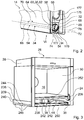
- FIG. 2 In addition to a door unit 64 with the door handle 62, the domestic appliance door 14 for transmitting the part of the weight of a coupling unit 34 with a contact portion 36 which the domestic appliance door 14 in an assembled state with the storage unit 38th coupled.
- the door unit 64 has an outer surface 32, which the domestic appliance door 14 in an operating position and in particular in a closed state of the household appliance door 14 and when the household appliance door 14 is pushed into the storage space 18, it is partially bounded laterally in a horizontal direction.
- the contact region 36 is arranged.
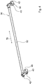
- the coupling unit 34 which is a part of the door storage unit 20, is formed by an axle unit 54, which has a hexagonal steel bar 66 and two integral plastic storage units 68, which are each attached positively to one end of the steel bar 66 and mirror-inverted , In a circumferential direction 70 of the steel bar 66, the door unit 64 is rotatably supported by the bearing units 68 about an axis 76 which extends in a horizontal direction.
- the bearing units 68 slide bearing surfaces 84 ( FIG. 6 ), which together with corresponding sliding bearing surfaces of the door unit 64 form a sliding bearing.
- the bearing units 68 form retaining means which, in particular in a closed position of the household appliance door 14, absorb a weight force of the domestic appliance door 14 and hold the domestic appliance door 14 - in cooperation with other holding means - in the closed position.
- the bearing units 68 are non-rotatable in the circumferential direction 70 against the steel rod 66 due to a bending of the steel rod 66.
- an embodiment of the axle unit 54 is also conceivable in which the steel rod 66 is dispensed with. It is also conceivable that the bearing units 68 are formed integrally with the steel rod 66 and are also made of steel.
- the contact region 36 is formed by an end section 56 of the axis unit 54 (FIG. FIG. 2 ).
- the bearing units 68 have elevations 72 with flat surface parts 74, which extend mainly in a direction perpendicular to the axis 76.
- a surface of the projections 72 and in particular the surface parts 74 form the contact region 36.
- FIG. 3 shows a schematic representation of the household appliance 26 without the appliance door 14 in a lateral frontal view.
- the bearing unit 38 is movably supported by two guide slots 44 of the household appliance 26 relative to the domestic appliance housing 28.
- the guide slots 44 which are formed mirror-inverted to each other, limit a portion of the storage space 18 in a front view of the domestic appliance on a right and a left side.
- the bearing unit 38 designed as a ball bearing bearings 42 with steel outer rings ( FIG. 4 ), which roll when inserting the appliance door 14 on the guide slot 44 formed from polypropylene and long glass fibers and are guided in this way.
- the rolling bearings 42 are attached to two torque transmitting means 48, 50 of the bearing unit 38.
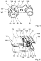
- the bearing unit 38 has a coupling means 52 formed by a rod, at the ends of which the torque transmission means 48, 50 are arranged in main directions of extension 78 of the coupling means 52 with the aid of recesses 51 (FIG. FIG. 5 ) are plugged.
- a movement of one of the torque transmission means 48, 50 automatically leads to a movement of the other torque transmission means 48, 50 due to the coupling means 52.
- the torque transmission means 48, 50 each have a receiving area 40, which in a mounted state of the appliance door 14, the elevations 72 of the storage units 68th and thus the contact areas 36 receives.
- the receiving region 40 is partially delimited by a contact surface 49 of the torque-transmitting means 48, 50, which rests against the contact region 36 in an assembled state of the appliance door 14 and transmits a torque to the contact region 36 and thus the coupling unit 34, which during a movement of the appliance door 14 on the coupling unit 34 exerts a torque by which the coupling unit 34 is rotated relative to the door unit 64.
- a surface part of the elevation 72 opposite the planar surface part 74 also acts, which rests against a contact surface 46 of the torque-transmitting means 48, 50.
- the projections 72 (FIG. 2) act as bearing means 86, by applying part of the weight of the appliance door 14 and the door unit 64 to the abutment surface 49 and to a lower boundary surface 80 of the torque transmitting means 48, 50 the recording area 40 partially limited in the vertical direction down, transmitted.
- the torque transmission means 48, 50 thus function as holding means 90, which in particular hold the closed household appliance door 14 in position.
- the elevation 72 forms a further functional means 88-namely, a guide means 58-of the bearing unit 68 in that the contact area 36 slides on a bearing surface 46 when the household appliance door 14 is uncoupled from the storage unit 38, thereby guiding the appliance door 14. Accordingly, the contact region 36 functions as a guide surface 82. A maintenance or cleaning of the appliance door 14 can advantageously take place by the uncoupling.
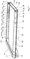
- FIG. 7 shows a schematic representation of the decoupled from the storage unit 38 household appliance door 14, wherein an intermediate disc and an inner pane 141 (see FIG. 1 ) of the door unit 64 have been removed.
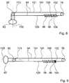
- the door handle 62 is attached to rollers 111, 113 which rotatably support it about an axis 92. In an operating position, the axis 92 extends in a horizontal direction.
- On the rollers 111, 113 is in each case a torque transmission means 94, 95 fixed such that by means of the torque transmission means 94, 95 each have a torque on the rollers 111, 113 is transferable, which rotates the door handle 62 about the axis 92.
- a torque can be transmitted to the torque transmitting means 94, 95 by means of the door handle 62.
- the torque transmission means 94, 95 each have a cable pull 181, which is deflected by one hundred and eighty degrees through the rollers 111 and 113, respectively.
- a bolt 115 is attached to one of the torque transmission means 94, 95 (see FIG. 6 ) and engages in a receiving region 116 of the bearing units 68, whereby the torque transmission means 94, 95 are positively secured to the bearing units 68.
- the torque transmission means 94, 95 extend in grooves 127 of the bearing units 68 and are thus secured in a form-fitting manner along the axis 76.
- the door unit 64 is designed as a profiled rail door and has two profiled rails 121, 123.
- the bearing units 68 are partially arranged in recesses 163 of the profile rails 121, 123.
- the recesses 163 are bounded by non-illustrated bearing surfaces of the rails 121, 123.
- the sliding bearing surfaces 84 of the bearing units 68 slide against the corresponding bearing surfaces of the profiled rails 121, 123.
- the rollers 111, 113 and thus the door handle 62 are rotatably mounted by means of the profiled rails 121, 123.
- On the profile rails 121, 123 each one fastening means 98 is fixed relative to the rails 121, 123 immovably.
- the door unit 64 also has a first and a second spring means 96, 102, which are formed as coil springs.
- a first end of the first spring means 96 is hung on the first attachment portion 100, a first end of the second spring means 102 is hooked on the second attachment portion 104.
- At two ends of the cable 181 eyelets 117, 119 of the torque transmission means 94, 95 are further attached.
- a second end of the spring means 96 is further attached to the eyelet 117.
- the spring means 96 is disposed between the eyelet 125 and the roller 113.
- a second end of the second spring means 102 is attached to the eyelet 119.
- the second spring means 102 is disposed between the eyelet 125 and the bearing unit 68.
- the first spring means 96 has a significantly greater spring stiffness than the second spring means 102.
- the spring means 96, 102 keep the cable 181 stretched in an assembled state.
- the bearing unit 38 can optionally be detected by a locking unit 161 in a position in which the bearing unit 38 is arranged immediately before uncoupling. If this option is used, after disconnecting the household appliance door 14, guide surfaces 143, 145 of the storage unit 38 facilitate coupling the household appliance door 14 to the storage unit 38, by guiding the raised portions 72 when introduced into the receiving area 40 and thus also the storage units 68. Furthermore, in the coupling operation, the rollers 171, 173 of the guide means 24 (see FIG FIG. 1 ) in lateral grooves 175 of the household appliance door 14, which partially delimit the household appliance door 14 in an operating position laterally ( FIG. 2 ).
- the projections 72 are in the locking position. If a user then attempts to move the appliance door 14 in the direction of the surface extension 22 away from the storage unit 38, this is prevented by the projections 72 abutting the undercuts 147, as a result of which the projections 72 remain in the receiving areas 40.
- the locking means 195 engages a recess 201 of a locking means 200 of the locking unit 161, which is fixed to the guide means 24, that the guide means 24 and the locking means 200 relative to each other about an axis 204 which is parallel to the axis 193 and is rotated at a rotation of the guide means 24 with the guide means 24 are rotatable.
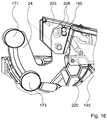
- the locking means 195 is with respect to the directions of rotation about the axis 193 on a housing-fixed guide member 203 (see FIG. 16 ) of the home appliance device. Therefore, when the locking means 195 is in the locking position, rotation of the guide means 24 about the axis 193 is prevented and the guide means 24 is thus fixed in a certain rotational position.
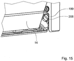
- an operator or fitter for fixing the appliance door storage unit 191 for example with the aid of a coin, can insert into a groove 206 of an actuating means 199 (FIG. FIG. 15 ), which is designed as a pivot, the locking unit 161 penetrate and this starting from a starting position, in which an opening and closing of the appliance door 14 is possible to rotate by ninety degrees ( Figures 13 and 14 ). If the home appliance door storage unit 191 is in a swing position different from the take-off swing position, the actuator 197 is cocked and thereby expanded by this rotation of the operation means 199 since the operation means 197 is fixed to the operation means 199.
- the locking means 195 Due to the tightening of the actuating means 197, the locking means 195, which is attached to the actuating means 197, in a vertical downward direction against a sliding surface 202 of the locking means 200, which is arranged on an upper side of the locking means 200 is pressed.
- a locking of the locking means 195 in the recess 201 pivots the operator or fitter the appliance door 14 in the pivot directions 10, 12 (see FIG. 1 ), wherein the locking means 195 slides on the sliding surface 202 until the domestic appliance door storage unit 191 is in the withdrawal pivot position and the locking means 195 in the recess 201 due to a pressure which the actuating means 197 on the locking means 195 downwardly engages.
Landscapes
- Engineering & Computer Science (AREA)
- Chemical & Material Sciences (AREA)
- Combustion & Propulsion (AREA)
- Mechanical Engineering (AREA)
- General Engineering & Computer Science (AREA)
- Support Devices For Sliding Doors (AREA)
- Electric Ovens (AREA)
- Power-Operated Mechanisms For Wings (AREA)
Claims (15)
- Dispositif de guidage de porte d'appareil ménager comprenant au moins un moyen de guidage de porte (209) lequel présente une surface de guidage (210), caractérisé en ce que la surface de guidage (210) est formée au moins en partie à partir d'une matière plastique, le moyen de guidage de porte (209) étant réalisé d'une seule pièce en matière plastique.
- Dispositif de guidage de porte d'appareil ménager selon la revendication 1,
caractérisé en ce que
le moyen de guidage de porte (209) présente une coulisse (44), laquelle est ménagée pour guider une porte (14) d'appareil ménager. - Dispositif de guidage de porte d'appareil ménager selon la revendication 2,
caractérisé en ce que
la coulisse (44) est ménagée pour introduire la porte (14) d'appareil ménager au moins en grande partie dans un espace de stockage (18) au moyen d'un mouvement coulissant. - Dispositif de guidage de porte d'appareil ménager selon l'une quelconque des revendications précédentes,
caractérisé par
au moins un moyen d'amortissement (212), lequel, dans au moins un état monté, est couplé au moyen de guidage de porte (209). - Dispositif de guidage de porte d'appareil ménager selon la revendication 4,
caractérisé en ce que
le moyen d'amortissement (212), dans au moins un état monté, est disposé au moins en partie dans une zone de logement (214) du moyen de guidage de porte (209). - Dispositif de guidage de porte d'appareil ménager selon l'une quelconque des revendications 4 ou 5,
caractérisé en ce que
le moyen de guidage de porte (209) présente un moyen d'enclenchement (216), lequel, dans au moins un état monté, fixe le moyen d'amortissement (212). - Dispositif de guidage de porte d'appareil ménager selon l'une quelconque des revendications précédentes,
caractérisé en ce que
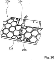
le moyen de guidage de porte (209) présente au moins une structure en nervures (218). - Dispositif de guidage de porte d'appareil ménager selon la revendication 7,
caractérisé en ce que
la structure en nervures (218) est réalisée en forme d'alvéoles. - Dispositif de guidage de porte d'appareil ménager selon l'une quelconque des revendications précédentes,
caractérisé par
au moins une surface de glissement (220) du moyen de guidage de porte (209) et au moins un moyen de palier (222), lequel est ménagé, en cas d'au moins un mouvement par rapport au moyen de guidage de porte (209), pour glisser sur la surface de glissement (220). - Dispositif de guidage de porte d'appareil ménager selon la revendication 9,
caractérisé en ce que
la surface de glissement (220) est réalisée comme partie d'une enveloppe de cylindre. - Dispositif de guidage de porte d'appareil ménager selon l'une quelconque des revendications 9 ou 10,
caractérisé en ce que
la surface de glissement (220) sert à un glissement du moyen de palier (222) dans au moins un état d'usure. - Dispositif de guidage de porte d'appareil ménager selon l'une quelconque des revendications précédentes,
caractérisé en ce que
le moyen de guidage de porte (209) présente au moins une zone partielle qui est au moins formée en polypropylène et/ou en fibres de verre longues. - Dispositif de guidage de porte d'appareil ménager selon l'une quelconque des revendications précédentes,
caractérisé en ce que
le moyen de guidage de porte (209) présente un moyen de fixation (224), lequel est ménagé pour fixer un câble. - Dispositif de guidage de porte d'appareil ménager selon l'une quelconque des revendications précédentes,
caractérisé par
au moins un palier de roulement (42) muni d'une bague extérieure en métal, laquelle est guidée par la surface de guidage (210) dans au moins une opération de service. - Dispositif de guidage de porte d'appareil ménager selon l'une quelconque des revendications précédentes,
caractérisé en ce que
le moyen de guidage de porte (209) présente au moins une zone de logement (228), laquelle est ménagée pour loger au moins un moyen d'actionnement (199).
Applications Claiming Priority (1)
| Application Number | Priority Date | Filing Date | Title |
|---|---|---|---|
| DE102008010502A DE102008010502A1 (de) | 2008-02-22 | 2008-02-22 | Hausgerätetürführungsvorrichtung |
Publications (3)
| Publication Number | Publication Date |
|---|---|
| EP2093495A2 EP2093495A2 (fr) | 2009-08-26 |
| EP2093495A3 EP2093495A3 (fr) | 2014-04-02 |
| EP2093495B1 true EP2093495B1 (fr) | 2016-02-17 |
Family
ID=40679289
Family Applications (1)
| Application Number | Title | Priority Date | Filing Date |
|---|---|---|---|
| EP09100130.5A Active EP2093495B1 (fr) | 2008-02-22 | 2009-02-19 | Dispositif de commande de porte d'appareil ménager |
Country Status (2)
| Country | Link |
|---|---|
| EP (1) | EP2093495B1 (fr) |
| DE (1) | DE102008010502A1 (fr) |
Cited By (3)
| Publication number | Priority date | Publication date | Assignee | Title |
|---|---|---|---|---|
| US12035845B1 (en) | 2023-04-26 | 2024-07-16 | Sharkninja Operating Llc | Systems and methods for cooking pizza |
| US12372247B2 (en) | 2023-04-26 | 2025-07-29 | Sharkninja Operating Llc | Systems and methods for cooking pizza |
| USD1104596S1 (en) | 2023-05-31 | 2025-12-09 | Sharkninja Operating Llc | Cooking device |
Families Citing this family (3)
| Publication number | Priority date | Publication date | Assignee | Title |
|---|---|---|---|---|
| DE102012222161A1 (de) | 2012-12-04 | 2014-06-05 | BSH Bosch und Siemens Hausgeräte GmbH | Gargerät mit versenkbarer Tür und höhenverstellbarer Führungskulisse |
| TR201820546A1 (tr) * | 2018-12-26 | 2020-07-21 | Arcelik As | Yüksekli̇ği̇ ayarlanabi̇len ray i̇çeren bi̇r firin |
| EP4053518B1 (fr) * | 2019-11-06 | 2024-01-03 | A&D Company, Limited | Pare-brise pour une balance |
Family Cites Families (5)
| Publication number | Priority date | Publication date | Assignee | Title |
|---|---|---|---|---|
| DE8515431U1 (de) * | 1985-05-24 | 1987-05-14 | Bosch-Siemens Hausgeräte GmbH, 8000 München | Backofen |
| DE10208490A1 (de) | 2002-02-27 | 2004-02-05 | BSH Bosch und Siemens Hausgeräte GmbH | Haushaltsgerät |
| DE10211470A1 (de) * | 2002-03-15 | 2003-10-02 | Electrolux Home Prod Corp | Schiene eines insbesondere teleskopartigen Auszugssystems für Gargutträger eines Garofens und Auszugssystems |
| DE10228297A1 (de) * | 2002-06-25 | 2004-01-15 | BSH Bosch und Siemens Hausgeräte GmbH | Haushaltsgerät sowie Verfahren zur Herstellung eines Haushaltsgeräts |
| EP2026013A1 (fr) * | 2007-08-17 | 2009-02-18 | Electrolux Home Products Corporation N.V. | Appareil domestique comportant un chariot de porte détachable et mécanisme d'aide à la traction |
-
2008
- 2008-02-22 DE DE102008010502A patent/DE102008010502A1/de not_active Ceased
-
2009
- 2009-02-19 EP EP09100130.5A patent/EP2093495B1/fr active Active
Cited By (4)
| Publication number | Priority date | Publication date | Assignee | Title |
|---|---|---|---|---|
| US12035845B1 (en) | 2023-04-26 | 2024-07-16 | Sharkninja Operating Llc | Systems and methods for cooking pizza |
| US12372247B2 (en) | 2023-04-26 | 2025-07-29 | Sharkninja Operating Llc | Systems and methods for cooking pizza |
| US12408792B2 (en) | 2023-04-26 | 2025-09-09 | Sharkninja Operating Llc | Systems and methods for cooking pizza |
| USD1104596S1 (en) | 2023-05-31 | 2025-12-09 | Sharkninja Operating Llc | Cooking device |
Also Published As
| Publication number | Publication date |
|---|---|
| EP2093495A2 (fr) | 2009-08-26 |
| DE102008010502A1 (de) | 2009-08-27 |
| EP2093495A3 (fr) | 2014-04-02 |
Similar Documents
| Publication | Publication Date | Title |
|---|---|---|
| EP2093492B1 (fr) | Dispositif d'appareil ménager | |
| WO2020103981A1 (fr) | Frein de stationnement et son procédé de montage | |
| EP1481142B1 (fr) | Appareil electromenager et porte d'appareil electromenager | |
| EP2189725A2 (fr) | Dispositif d'appareil ménager | |
| EP2093495A2 (fr) | Dispositif de commande de porte d'appareil ménager | |
| WO2006087365A2 (fr) | Entrainement lineaire par moteur electrique | |
| EP1481198B1 (fr) | Appareil menager | |
| EP2093493B1 (fr) | Dispositif d'appareil ménager | |
| EP1481197B1 (fr) | Appareil menager | |
| EP1481141B1 (fr) | Appareil domestique et porte d'appareil domestique | |
| EP1481199B1 (fr) | Appareil menager et procede de fabrication d'un appareil menager | |
| EP1719860A1 (fr) | Porte d'appareil électroménager et appareil électroménager | |
| EP2093496B1 (fr) | Dispositif d'appareil ménager | |
| WO2023110169A1 (fr) | Ensemble de suspension pour porte coulissante | |
| EP1659298A2 (fr) | Entraînement linéaire | |
| DE102008010498B4 (de) | Hausgerätvorrichtung | |
| EP2486309B1 (fr) | Mécanisme d`accoupler | |
| EP3356629B1 (fr) | Ferrure pour porte coulissante et procédé de montage d'une porte coulissante | |
| EP2093494B1 (fr) | Dispositif d'appareil ménager | |
| WO2013110099A1 (fr) | Système de rétraction pour une pluralité d'éléments de meuble coulissants | |
| DE102005002822B4 (de) | Türscharnier für ein Haushaltsgerät | |
| WO2015173297A1 (fr) | Agencement de palier pour porte | |
| DE2911024A1 (de) | Antriebsvorrichtung zum verstellen von fensterscheiben, schiebedaechern u.dgl. von kraftfahrzeugen | |
| DE102008010500B4 (de) | Hausgerätvorrichtung | |
| WO2024013675A1 (fr) | Dispositif de réglage longitudinal et siège de véhicule |
Legal Events
| Date | Code | Title | Description |
|---|---|---|---|
| PUAI | Public reference made under article 153(3) epc to a published international application that has entered the european phase |
Free format text: ORIGINAL CODE: 0009012 |
|
| AK | Designated contracting states |
Kind code of ref document: A2 Designated state(s): AT BE BG CH CY CZ DE DK EE ES FI FR GB GR HR HU IE IS IT LI LT LU LV MC MK MT NL NO PL PT RO SE SI SK TR |
|
| AX | Request for extension of the european patent |
Extension state: AL BA RS |
|
| PUAL | Search report despatched |
Free format text: ORIGINAL CODE: 0009013 |
|
| AK | Designated contracting states |
Kind code of ref document: A3 Designated state(s): AT BE BG CH CY CZ DE DK EE ES FI FR GB GR HR HU IE IS IT LI LT LU LV MC MK MT NL NO PL PT RO SE SI SK TR |
|
| AX | Request for extension of the european patent |
Extension state: AL BA RS |
|
| RIC1 | Information provided on ipc code assigned before grant |
Ipc: F25D 23/02 20060101ALI20140225BHEP Ipc: D06F 37/10 20060101ALI20140225BHEP Ipc: A47L 15/42 20060101ALI20140225BHEP Ipc: F24C 15/02 20060101AFI20140225BHEP |
|
| 17P | Request for examination filed |
Effective date: 20141002 |
|
| RBV | Designated contracting states (corrected) |
Designated state(s): AT BE BG CH CY CZ DE DK EE ES FI FR GB GR HR HU IE IS IT LI LT LU LV MC MK MT NL NO PL PT RO SE SI SK TR |
|
| AKX | Designation fees paid |
Designated state(s): AT BE BG CH CY CZ DE DK EE ES FI FR GB GR HR HU IE IS IT LI LT LU LV MC MK MT NL NO PL PT RO SE SI SK TR |
|
| AXX | Extension fees paid |
Extension state: AL Extension state: BA Extension state: RS |
|
| RAP1 | Party data changed (applicant data changed or rights of an application transferred) |
Owner name: BSH HAUSGERAETE GMBH |
|
| 17Q | First examination report despatched |
Effective date: 20150316 |
|
| GRAP | Despatch of communication of intention to grant a patent |
Free format text: ORIGINAL CODE: EPIDOSNIGR1 |
|
| INTG | Intention to grant announced |
Effective date: 20150918 |
|
| GRAS | Grant fee paid |
Free format text: ORIGINAL CODE: EPIDOSNIGR3 |
|
| GRAA | (expected) grant |
Free format text: ORIGINAL CODE: 0009210 |
|
| AK | Designated contracting states |
Kind code of ref document: B1 Designated state(s): AT BE BG CH CY CZ DE DK EE ES FI FR GB GR HR HU IE IS IT LI LT LU LV MC MK MT NL NO PL PT RO SE SI SK TR |
|
| REG | Reference to a national code |
Ref country code: GB Ref legal event code: FG4D Free format text: NOT ENGLISH |
|
| REG | Reference to a national code |
Ref country code: CH Ref legal event code: EP |
|
| REG | Reference to a national code |
Ref country code: IE Ref legal event code: FG4D Free format text: LANGUAGE OF EP DOCUMENT: GERMAN |
|
| REG | Reference to a national code |
Ref country code: AT Ref legal event code: REF Ref document number: 775834 Country of ref document: AT Kind code of ref document: T Effective date: 20160315 |
|
| REG | Reference to a national code |
Ref country code: FR Ref legal event code: PLFP Year of fee payment: 8 |
|
| REG | Reference to a national code |
Ref country code: DE Ref legal event code: R096 Ref document number: 502009012139 Country of ref document: DE |
|
| REG | Reference to a national code |
Ref country code: NL Ref legal event code: MP Effective date: 20160217 |
|
| REG | Reference to a national code |
Ref country code: LT Ref legal event code: MG4D |
|
| PG25 | Lapsed in a contracting state [announced via postgrant information from national office to epo] |
Ref country code: NO Free format text: LAPSE BECAUSE OF FAILURE TO SUBMIT A TRANSLATION OF THE DESCRIPTION OR TO PAY THE FEE WITHIN THE PRESCRIBED TIME-LIMIT Effective date: 20160517 Ref country code: ES Free format text: LAPSE BECAUSE OF FAILURE TO SUBMIT A TRANSLATION OF THE DESCRIPTION OR TO PAY THE FEE WITHIN THE PRESCRIBED TIME-LIMIT Effective date: 20160217 Ref country code: IT Free format text: LAPSE BECAUSE OF FAILURE TO SUBMIT A TRANSLATION OF THE DESCRIPTION OR TO PAY THE FEE WITHIN THE PRESCRIBED TIME-LIMIT Effective date: 20160217 Ref country code: GR Free format text: LAPSE BECAUSE OF FAILURE TO SUBMIT A TRANSLATION OF THE DESCRIPTION OR TO PAY THE FEE WITHIN THE PRESCRIBED TIME-LIMIT Effective date: 20160518 Ref country code: FI Free format text: LAPSE BECAUSE OF FAILURE TO SUBMIT A TRANSLATION OF THE DESCRIPTION OR TO PAY THE FEE WITHIN THE PRESCRIBED TIME-LIMIT Effective date: 20160217 |
|
| PG25 | Lapsed in a contracting state [announced via postgrant information from national office to epo] |
Ref country code: LV Free format text: LAPSE BECAUSE OF FAILURE TO SUBMIT A TRANSLATION OF THE DESCRIPTION OR TO PAY THE FEE WITHIN THE PRESCRIBED TIME-LIMIT Effective date: 20160217 Ref country code: SE Free format text: LAPSE BECAUSE OF FAILURE TO SUBMIT A TRANSLATION OF THE DESCRIPTION OR TO PAY THE FEE WITHIN THE PRESCRIBED TIME-LIMIT Effective date: 20160217 Ref country code: NL Free format text: LAPSE BECAUSE OF FAILURE TO SUBMIT A TRANSLATION OF THE DESCRIPTION OR TO PAY THE FEE WITHIN THE PRESCRIBED TIME-LIMIT Effective date: 20160217 Ref country code: BE Free format text: LAPSE BECAUSE OF NON-PAYMENT OF DUE FEES Effective date: 20160229 Ref country code: PL Free format text: LAPSE BECAUSE OF FAILURE TO SUBMIT A TRANSLATION OF THE DESCRIPTION OR TO PAY THE FEE WITHIN THE PRESCRIBED TIME-LIMIT Effective date: 20160217 Ref country code: PT Free format text: LAPSE BECAUSE OF FAILURE TO SUBMIT A TRANSLATION OF THE DESCRIPTION OR TO PAY THE FEE WITHIN THE PRESCRIBED TIME-LIMIT Effective date: 20160617 Ref country code: LT Free format text: LAPSE BECAUSE OF FAILURE TO SUBMIT A TRANSLATION OF THE DESCRIPTION OR TO PAY THE FEE WITHIN THE PRESCRIBED TIME-LIMIT Effective date: 20160217 |
|
| REG | Reference to a national code |
Ref country code: CH Ref legal event code: PL |
|
| PG25 | Lapsed in a contracting state [announced via postgrant information from national office to epo] |
Ref country code: DK Free format text: LAPSE BECAUSE OF FAILURE TO SUBMIT A TRANSLATION OF THE DESCRIPTION OR TO PAY THE FEE WITHIN THE PRESCRIBED TIME-LIMIT Effective date: 20160217 Ref country code: LI Free format text: LAPSE BECAUSE OF NON-PAYMENT OF DUE FEES Effective date: 20160229 Ref country code: CH Free format text: LAPSE BECAUSE OF NON-PAYMENT OF DUE FEES Effective date: 20160229 Ref country code: EE Free format text: LAPSE BECAUSE OF FAILURE TO SUBMIT A TRANSLATION OF THE DESCRIPTION OR TO PAY THE FEE WITHIN THE PRESCRIBED TIME-LIMIT Effective date: 20160217 |
|
| REG | Reference to a national code |
Ref country code: DE Ref legal event code: R097 Ref document number: 502009012139 Country of ref document: DE |
|
| PG25 | Lapsed in a contracting state [announced via postgrant information from national office to epo] |
Ref country code: CZ Free format text: LAPSE BECAUSE OF FAILURE TO SUBMIT A TRANSLATION OF THE DESCRIPTION OR TO PAY THE FEE WITHIN THE PRESCRIBED TIME-LIMIT Effective date: 20160217 Ref country code: RO Free format text: LAPSE BECAUSE OF FAILURE TO SUBMIT A TRANSLATION OF THE DESCRIPTION OR TO PAY THE FEE WITHIN THE PRESCRIBED TIME-LIMIT Effective date: 20160217 Ref country code: SK Free format text: LAPSE BECAUSE OF FAILURE TO SUBMIT A TRANSLATION OF THE DESCRIPTION OR TO PAY THE FEE WITHIN THE PRESCRIBED TIME-LIMIT Effective date: 20160217 |
|
| REG | Reference to a national code |
Ref country code: IE Ref legal event code: MM4A |
|
| PLBE | No opposition filed within time limit |
Free format text: ORIGINAL CODE: 0009261 |
|
| STAA | Information on the status of an ep patent application or granted ep patent |
Free format text: STATUS: NO OPPOSITION FILED WITHIN TIME LIMIT |
|
| 26N | No opposition filed |
Effective date: 20161118 |
|
| PG25 | Lapsed in a contracting state [announced via postgrant information from national office to epo] |
Ref country code: IE Free format text: LAPSE BECAUSE OF NON-PAYMENT OF DUE FEES Effective date: 20160219 |
|
| REG | Reference to a national code |
Ref country code: FR Ref legal event code: PLFP Year of fee payment: 9 |
|
| PG25 | Lapsed in a contracting state [announced via postgrant information from national office to epo] |
Ref country code: SI Free format text: LAPSE BECAUSE OF FAILURE TO SUBMIT A TRANSLATION OF THE DESCRIPTION OR TO PAY THE FEE WITHIN THE PRESCRIBED TIME-LIMIT Effective date: 20160217 Ref country code: BG Free format text: LAPSE BECAUSE OF FAILURE TO SUBMIT A TRANSLATION OF THE DESCRIPTION OR TO PAY THE FEE WITHIN THE PRESCRIBED TIME-LIMIT Effective date: 20160517 |
|
| REG | Reference to a national code |
Ref country code: AT Ref legal event code: MM01 Ref document number: 775834 Country of ref document: AT Kind code of ref document: T Effective date: 20160219 |
|
| PG25 | Lapsed in a contracting state [announced via postgrant information from national office to epo] |
Ref country code: AT Free format text: LAPSE BECAUSE OF NON-PAYMENT OF DUE FEES Effective date: 20160219 |
|
| PG25 | Lapsed in a contracting state [announced via postgrant information from national office to epo] |
Ref country code: MT Free format text: LAPSE BECAUSE OF FAILURE TO SUBMIT A TRANSLATION OF THE DESCRIPTION OR TO PAY THE FEE WITHIN THE PRESCRIBED TIME-LIMIT Effective date: 20160217 |
|
| REG | Reference to a national code |
Ref country code: FR Ref legal event code: PLFP Year of fee payment: 10 |
|
| PG25 | Lapsed in a contracting state [announced via postgrant information from national office to epo] |
Ref country code: HU Free format text: LAPSE BECAUSE OF FAILURE TO SUBMIT A TRANSLATION OF THE DESCRIPTION OR TO PAY THE FEE WITHIN THE PRESCRIBED TIME-LIMIT; INVALID AB INITIO Effective date: 20090219 Ref country code: CY Free format text: LAPSE BECAUSE OF FAILURE TO SUBMIT A TRANSLATION OF THE DESCRIPTION OR TO PAY THE FEE WITHIN THE PRESCRIBED TIME-LIMIT Effective date: 20160217 |
|
| PG25 | Lapsed in a contracting state [announced via postgrant information from national office to epo] |
Ref country code: MK Free format text: LAPSE BECAUSE OF FAILURE TO SUBMIT A TRANSLATION OF THE DESCRIPTION OR TO PAY THE FEE WITHIN THE PRESCRIBED TIME-LIMIT Effective date: 20160217 Ref country code: HR Free format text: LAPSE BECAUSE OF FAILURE TO SUBMIT A TRANSLATION OF THE DESCRIPTION OR TO PAY THE FEE WITHIN THE PRESCRIBED TIME-LIMIT Effective date: 20160217 Ref country code: LU Free format text: LAPSE BECAUSE OF NON-PAYMENT OF DUE FEES Effective date: 20160219 Ref country code: MC Free format text: LAPSE BECAUSE OF FAILURE TO SUBMIT A TRANSLATION OF THE DESCRIPTION OR TO PAY THE FEE WITHIN THE PRESCRIBED TIME-LIMIT Effective date: 20160217 Ref country code: TR Free format text: LAPSE BECAUSE OF FAILURE TO SUBMIT A TRANSLATION OF THE DESCRIPTION OR TO PAY THE FEE WITHIN THE PRESCRIBED TIME-LIMIT Effective date: 20160217 Ref country code: IS Free format text: LAPSE BECAUSE OF FAILURE TO SUBMIT A TRANSLATION OF THE DESCRIPTION OR TO PAY THE FEE WITHIN THE PRESCRIBED TIME-LIMIT Effective date: 20160217 |
|
| PGFP | Annual fee paid to national office [announced via postgrant information from national office to epo] |
Ref country code: FR Payment date: 20200220 Year of fee payment: 12 |
|
| PG25 | Lapsed in a contracting state [announced via postgrant information from national office to epo] |
Ref country code: FR Free format text: LAPSE BECAUSE OF NON-PAYMENT OF DUE FEES Effective date: 20210228 |
|
| REG | Reference to a national code |
Ref country code: DE Ref legal event code: R084 Ref document number: 502009012139 Country of ref document: DE |
|
| PGFP | Annual fee paid to national office [announced via postgrant information from national office to epo] |
Ref country code: GB Payment date: 20260219 Year of fee payment: 18 |
|
| PGFP | Annual fee paid to national office [announced via postgrant information from national office to epo] |
Ref country code: DE Payment date: 20260228 Year of fee payment: 18 |