EP2093571A2 - Système automatique pour la manipulation des dispositifs microfluidiques - Google Patents
Système automatique pour la manipulation des dispositifs microfluidiques Download PDFInfo
- Publication number
- EP2093571A2 EP2093571A2 EP09002994A EP09002994A EP2093571A2 EP 2093571 A2 EP2093571 A2 EP 2093571A2 EP 09002994 A EP09002994 A EP 09002994A EP 09002994 A EP09002994 A EP 09002994A EP 2093571 A2 EP2093571 A2 EP 2093571A2
- Authority
- EP
- European Patent Office
- Prior art keywords
- chip
- microfluidic
- cartridge
- deck
- chips
- Prior art date
- Legal status (The legal status is an assumption and is not a legal conclusion. Google has not performed a legal analysis and makes no representation as to the accuracy of the status listed.)
- Granted
Links
Images







Classifications
-
- G—PHYSICS
- G01—MEASURING; TESTING
- G01N—INVESTIGATING OR ANALYSING MATERIALS BY DETERMINING THEIR CHEMICAL OR PHYSICAL PROPERTIES
- G01N35/00—Automatic analysis not limited to methods or materials provided for in any single one of groups G01N1/00 - G01N33/00; Handling materials therefor
- G01N35/00584—Control arrangements for automatic analysers
-
- B—PERFORMING OPERATIONS; TRANSPORTING
- B01—PHYSICAL OR CHEMICAL PROCESSES OR APPARATUS IN GENERAL
- B01L—CHEMICAL OR PHYSICAL LABORATORY APPARATUS FOR GENERAL USE
- B01L3/00—Containers or dishes for laboratory use, e.g. laboratory glassware; Droppers
- B01L3/50—Containers for the purpose of retaining a material to be analysed, e.g. test tubes
- B01L3/502—Containers for the purpose of retaining a material to be analysed, e.g. test tubes with fluid transport, e.g. in multi-compartment structures
- B01L3/5027—Containers for the purpose of retaining a material to be analysed, e.g. test tubes with fluid transport, e.g. in multi-compartment structures by integrated microfluidic structures, i.e. dimensions of channels and chambers are such that surface tension forces are important, e.g. lab-on-a-chip
- B01L3/502715—Containers for the purpose of retaining a material to be analysed, e.g. test tubes with fluid transport, e.g. in multi-compartment structures by integrated microfluidic structures, i.e. dimensions of channels and chambers are such that surface tension forces are important, e.g. lab-on-a-chip characterised by interfacing components, e.g. fluidic, electrical, optical or mechanical interfaces
-
- B—PERFORMING OPERATIONS; TRANSPORTING
- B01—PHYSICAL OR CHEMICAL PROCESSES OR APPARATUS IN GENERAL
- B01L—CHEMICAL OR PHYSICAL LABORATORY APPARATUS FOR GENERAL USE
- B01L9/00—Supporting devices; Holding devices
- B01L9/52—Supports specially adapted for flat sample carriers, e.g. for plates, slides, chips
- B01L9/527—Supports specially adapted for flat sample carriers, e.g. for plates, slides, chips for microfluidic devices, e.g. used for lab-on-a-chip
-
- G—PHYSICS
- G01—MEASURING; TESTING
- G01N—INVESTIGATING OR ANALYSING MATERIALS BY DETERMINING THEIR CHEMICAL OR PHYSICAL PROPERTIES
- G01N21/00—Investigating or analysing materials by the use of optical means, i.e. using sub-millimetre waves, infrared, visible or ultraviolet light
- G01N21/01—Arrangements or apparatus for facilitating the optical investigation
- G01N21/03—Cuvette constructions
- G01N21/05—Flow-through cuvettes
-
- G—PHYSICS
- G01—MEASURING; TESTING
- G01N—INVESTIGATING OR ANALYSING MATERIALS BY DETERMINING THEIR CHEMICAL OR PHYSICAL PROPERTIES
- G01N21/00—Investigating or analysing materials by the use of optical means, i.e. using sub-millimetre waves, infrared, visible or ultraviolet light
- G01N21/01—Arrangements or apparatus for facilitating the optical investigation
- G01N21/11—Filling or emptying of cuvettes
-
- G—PHYSICS
- G01—MEASURING; TESTING
- G01N—INVESTIGATING OR ANALYSING MATERIALS BY DETERMINING THEIR CHEMICAL OR PHYSICAL PROPERTIES
- G01N21/00—Investigating or analysing materials by the use of optical means, i.e. using sub-millimetre waves, infrared, visible or ultraviolet light
- G01N21/01—Arrangements or apparatus for facilitating the optical investigation
- G01N21/13—Moving of cuvettes or solid samples to or from the investigating station
-
- G—PHYSICS
- G01—MEASURING; TESTING
- G01N—INVESTIGATING OR ANALYSING MATERIALS BY DETERMINING THEIR CHEMICAL OR PHYSICAL PROPERTIES
- G01N35/00—Automatic analysis not limited to methods or materials provided for in any single one of groups G01N1/00 - G01N33/00; Handling materials therefor
- G01N35/02—Automatic analysis not limited to methods or materials provided for in any single one of groups G01N1/00 - G01N33/00; Handling materials therefor using a plurality of sample containers moved by a conveyor system past one or more treatment or analysis stations
- G01N35/04—Details of the conveyor system
-
- G—PHYSICS
- G01—MEASURING; TESTING
- G01N—INVESTIGATING OR ANALYSING MATERIALS BY DETERMINING THEIR CHEMICAL OR PHYSICAL PROPERTIES
- G01N35/00—Automatic analysis not limited to methods or materials provided for in any single one of groups G01N1/00 - G01N33/00; Handling materials therefor
- G01N35/10—Devices for transferring samples or any liquids to, in, or from, the analysis apparatus, e.g. suction devices, injection devices
- G01N35/1095—Devices for transferring samples or any liquids to, in, or from, the analysis apparatus, e.g. suction devices, injection devices for supplying the samples to flow-through analysers
-
- B—PERFORMING OPERATIONS; TRANSPORTING
- B01—PHYSICAL OR CHEMICAL PROCESSES OR APPARATUS IN GENERAL
- B01L—CHEMICAL OR PHYSICAL LABORATORY APPARATUS FOR GENERAL USE
- B01L2300/00—Additional constructional details
- B01L2300/08—Geometry, shape and general structure
- B01L2300/0809—Geometry, shape and general structure rectangular shaped
- B01L2300/0819—Microarrays; Biochips
-
- B—PERFORMING OPERATIONS; TRANSPORTING
- B01—PHYSICAL OR CHEMICAL PROCESSES OR APPARATUS IN GENERAL
- B01L—CHEMICAL OR PHYSICAL LABORATORY APPARATUS FOR GENERAL USE
- B01L3/00—Containers or dishes for laboratory use, e.g. laboratory glassware; Droppers
- B01L3/50—Containers for the purpose of retaining a material to be analysed, e.g. test tubes
- B01L3/502—Containers for the purpose of retaining a material to be analysed, e.g. test tubes with fluid transport, e.g. in multi-compartment structures
- B01L3/5027—Containers for the purpose of retaining a material to be analysed, e.g. test tubes with fluid transport, e.g. in multi-compartment structures by integrated microfluidic structures, i.e. dimensions of channels and chambers are such that surface tension forces are important, e.g. lab-on-a-chip
-
- G—PHYSICS
- G01—MEASURING; TESTING
- G01N—INVESTIGATING OR ANALYSING MATERIALS BY DETERMINING THEIR CHEMICAL OR PHYSICAL PROPERTIES
- G01N21/00—Investigating or analysing materials by the use of optical means, i.e. using sub-millimetre waves, infrared, visible or ultraviolet light
- G01N21/01—Arrangements or apparatus for facilitating the optical investigation
- G01N21/03—Cuvette constructions
- G01N2021/0346—Capillary cells; Microcells
-
- G—PHYSICS
- G01—MEASURING; TESTING
- G01N—INVESTIGATING OR ANALYSING MATERIALS BY DETERMINING THEIR CHEMICAL OR PHYSICAL PROPERTIES
- G01N21/00—Investigating or analysing materials by the use of optical means, i.e. using sub-millimetre waves, infrared, visible or ultraviolet light
- G01N21/01—Arrangements or apparatus for facilitating the optical investigation
- G01N21/03—Cuvette constructions
- G01N21/05—Flow-through cuvettes
- G01N2021/058—Flat flow cell
Definitions
- This invention is generally directed to microfluidic chip devices and an automated apparatus for providing small volume, multifunction lab procedures on microfluidic chips.
- microfluidic refers to a system or device having micron or submicron scale channels and chambers.
- microfluidic systems include a microfluidic device, or chip, that has networks of integrated submicron channels in which materials are transported, mixed, separated and detected.
- Microfluidic systems typically also contain components that provide fluid driving forces to the chip and that detect signals emanating from the chip.
- Microfluidic chips may be fabricated from a number of different materials, including glass or polymeric materials.
- An example of a commercially available microfluidic chip is shown in FIG. 1.
- FIG. 1A is a topside view of the chip
- FIG. 1B is a bottom side view of the same chip.
- That chip a DNA LabChip ® manufactured by Caliper Life Sciences, Inc. of Mountain View California, is used with the Agilent 2100 Bioanalyzer system manufactured by Agilent Technologies, Inc. of Palo Alto California.
- the chip in FIG. 1 has two major components: a working part 128 made of glass, and a plastic caddy or mount 127 bonded to the working part.
- the working part contains microfluidic channels in its interior, and wells on its exterior that provide access to the microfluidic channels.
- the working part is typically fabricated by bonding together two or more planar substrate layers.
- the microfluidic channels in the working part are formed when one planar substrate encloses grooves formed on another planar substrate.
- the mount protects the working part of the chip, and provides for easier handling of the chip by a user. The increased ease of handling partially results from the fact that the mount 127 is larger than the working part of the device, which in many cases is too small and thin to be easily handled.
- the mount may be fabricated from any suitable polymeric material, such as an acrylic or thermoplastic.
- the glass working part is typically bonded to the polymeric mount using a UV-cured adhesive.
- Reservoirs 129 in the mount 127 provide access to the walls on the working part of the chip.
- the reservoirs 129 hold much greater volumes of material than the wells in the working part 128, thus providing an interface between the macro-environment of the user and the microenvironment of the wells and channels of the microfluidic device.
- the use of the plastic mount 127 to hold the working part 128 provides several advantages, the use of the mount may have some disadvantages.
- the polymeric material of the mount 127 may cause dye interaction and surface chemistry issues with respect to the materials applied to the reservoirs.
- mount 127 and the adhesive used to adhere mount 127 to the working part may affect the life span of the chip when shipped and stored.
- microfluidic chip in FIG. 1 is a "planar” chip.
- a planar chip the only access to the microchannels in the chip is through the reservoirs 129 in the caddy and in-turn through the wells in the working part 128.
- Another type of microfluidic chip is a "sipper” chip, which has a small tube or capillary (the “sipper") extending from the chip through which fluids stored outside the chip can be directed into the microfluidic channels in the chip.
- Typical sipper chips have between one and twelve sippers. In use, the sipper is placed in a receptacle having sample material and minute quantities of the sample material are introduced, or "sipped” through the capillary tube to the microfluidic channels of the chip. This sipping process can be repeated to introduce any number of different sample materials into the chip. Sippers make it easier to carry out high-throughput analysis of numerous samples on a single microfluidic chip.
- Microfluidic chips fabricated from glass are typically shipped after having been preconditioned or "primed” with sodium hydroxide under pressure.
- the preconditioning process prepares the surface of the chip for use and increases the lifetime of the chip.
- the extremely caustic nature of the preconditioning fluid makes it desirable to have the preconditioning performed by technicians prior to shipping as opposed to having the end user apply the sodium hydroxide.
- the chips are then shipped in liquid to preserve the preconditioned surface state.
- the fluid is generally distilled water containing a preservative such as EDTA or a buffer such as tris-tricine.
- EDTA EDTA
- a buffer such as tris-tricine.
- This type of shipping container is undesirable for various reasons. First, the end user must "fish" the chip out of the fluid in which it has been shipped. Secondly, the submersion may weaken the adhesive bonding between the laminated substrate layers in the chip, or the bonding between the working part of the chip and a mounting fixture holding the working part of the chip. Those types of delamination may render the chip unusable. Finally, as the chips are capable of being reused many times, the user must replace the chips into the storage fluid between uses, which increases the risk of contaminating the chip.
- microfluidic devices have become advanced enough that multiple analyses can be performed on a single chip using very small volumes of sample material, the preparation and handling of chips often requires a great deal of human effort and time.
- the reservoirs on a chip are also vulnerable to evaporation and/or current leakage between reservoirs causing changes in concentration of sample materials or in fluid flow through the chip, which can make the chip function inaccurately.
- the present invention is directed towards an automated microfluidic chip processing apparatus.
- One aspect of the present invention is an automated microfluidic chip processing apparatus including a chip handling system, a fluid control device, and a detection system, wherein the chip handling system moves the chip to the fluid control device and detection system.
- a liquid handling system may be integrated into the automated microfluidic chip processing apparatus.
- Another aspect of the present invention includes a chip that is suitable for use in the present invention that does not utilize a mount conventionally found on microfluidic chips. Such a chip may have no mount or may use an alternative mount providing for smaller overall chip size. Yet another aspect of the present invention is a microfluidic chip with or without a mount having a pierceable film covering at least one of the reservoirs. Another aspect of the present invention is a cartridge for stacking, distributing and dispensing microfluidic chips, such as for use with an apparatus of the present invention.
- Another aspect of the present invention includes a method of processing a microfluidic chip including providing a microfluidic chip apparatus, including a chip handling system, a fluid control system, and a detection system.
- the method includes providing at least one microfluidic chip including a sample material; positioning the chip with respect to a fluid control system and a detection system via a chip handling device; controlling the flow of a material through said chip via the fluid control system; and detecting results of an assay conducted on the chip via the detection system.
- aspects of the present invention include the apparatus described above having one or more of the following: a priming station, a washing station, a control system for controlling the apparatus, a data output system, an alignment system and/or the capability of simultaneously processing more than one chip.
- the present invention is directed towards an automated apparatus for processing a microfluidic chip.
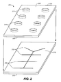
- An example of a microfluidic chip 204 is illustrated in FIG. 2 .
- the chip 204 shown is the working part of the chip without a mount.
- the chip 204 includes a bottom plate 212 formed from a solid substrate that is substantially planar in structure, and which has at least one substantially flat upper surface 216.
- the substrate could be fabricated from a variety of materials such as fused silica, glass, or plastic.
- the channels and/or chambers of the microfluidic chip 204 are formed when grooves 213 in the upper surface 216 of the bottom plate 212, are enclosed when the bottom plate 212 is bonded to a top plate 214.
- the grooves can be formed in the upper surface 216 of the bottom plate by any fabrication method capable of producing microscale features in the material forming the bottom plate.
- the grooves could be formed by a photolithographically defining the location of the grooves, and then etching the grooves into the upper surface 216 of the bottom plate.
- the grooves 213 could be formed by injection molding or by embossing.
- the grooves that will form the channels or chambers could be fabricated in the lower surface 205 of the top plate 214, or in both the upper surface 216 of the bottom plate 212 and the lower surface 205 of the top plate 214.
- the top plate 214 is substantially planar in structure, and can be formed from a solid substrate of fused silica, glass or plastic.
- the top plate 214 has both the first surface 205 and a second surface 207 opposite the first surface 205.
- the top plate 214 includes a plurality of apertures, holes or ports 215 disposed therethrough, e.g., from the first surface 205 to the second surface 207.
- the grooves and/or indentations 213 in the surface of the bottom plate 212 are enclosed to form microchannels and/or chambers.
- the apertures, holes or ports 215 disposed in the upper plate 214 of the chip are oriented such that they are in communication with at least one microchannel and/or chamber formed from the grooves or indentations 213 in the bottom plate 212, thus providing external access to the microscale channels and chambers.
- the apertures form wells that facilitate fluid or material introduction into the microchannels, as well as to provide ports through which electrodes or pressure hoses may apply electric fields or pressure differentials for controlling and directing fluid transport within the microfluidic chip.
- the wells typically hold about 500-5000 nl and have diameters of about 500 ⁇ m to 2000 ⁇ m.
- microfluidic chip includes the movement of material through microchannels arranged on the chip in a controlled manner.
- fluid movement may be controlled by the application of positive or negative partial pressure to certain reservoirs, so that fluid moves from locations of high pressure to locations of low pressure through the microchannels.
- Partial pressures may be applied by a pumping mechanism or the application of a vacuum force to a reservoir.
- electro-kinetics such as electrophoresis or electro-osmosis, wherein the fluid moves in response to the application of positive and negative voltages. Therefore, the fluid control system includes the capabilities for providing and controlling forces to move fluids through microfluidic channels.
- An embodiment of the apparatus of the present invention also includes a detection system in operation with the chip to provide data regarding the concentration of one or more materials in a microfluidic channel.
- concentration information include, but are not limited to, optical absorbance, refractive index changes, fluorescence emission, chemiluminescence, Raman spectroscopy, electrical conductance, electrochemical amperiometric measurements, and acoustic wave propagation. These various detection methods are discussed, for example, in U.S. Patent No. 5,858,195 , the disclosure of which is incorporated herein by reference in its entirety.
- the detector system is capable of detecting more than one sample material in a microfluidic chip, if desired.
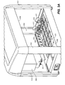
- FIG. 3A shows an apparatus 300 in which multiple microfluidic chips, such as chip 204, can be used.
- the apparatus includes a deck 302 and a robotic head 306 that is capable of moving in the x-y-z directions across deck 302.
- Robotic head 306 is suspended from a hood 308 that is supported by supports 310.
- Deck 302 has been divided into universal stations 320. Universal stations 320 may contain any type of materials, plates, holders, etc., that may be used during the microfluidic chip processing.
- robotic head 306 also incorporates a liquid handling device.
- sample and buffer material must be added to the reservoirs on the chip.
- the liquid handling system provides materials to chip 204 for various procedures.
- the liquid handling device can be any automated apparatus for transferring liquid.
- the liquid handling system may transfer liquid from bulk storage or may transfer liquid materials from macro-volume receptacles to a micro- or nano-volume receptacle.
- a liquid handling system may be capable of transferring sample material, buffer, or other materials into the micro-, nano-or Pico-volume reservoirs of the microfluidic chip 204.
- the liquid handling system may be a capillary or other pipetting system using a volume control, to aspirate and dispense materials.
- volume controls include, but are not limited to, peristaltic pumps, syringe pumps, solenoid inertial dispensing systems, flowmeters, or piezoelectric transducer controls.
- the liquid handling system may include any type of nozzle for directing the material into the reservoirs of the microfluidic chips.
- One example of a liquid handling system with nano-volume capacity includes an array of stainless steel cannula, each having a ceramic nozzle that can deliver volumes as low as 100 nl.
- 6,592,825 discloses the transfer of even smaller volumes of material to and from microfluidic plates, for example, picoliter volumes, which may be incorporated into the present invention.
- An array of disposable tips may be used or a fixed cannula with permanent tips.
- the liquid handling system may have an interchangeable arrangement of tips and arrays for a variety of liquid handling procedures.
- Disposable tips and other features of the liquid handling device may be provided in one or more of the universal stations 320 provided in deck 302.
- the liquid handling system is generally capable transferring materials from any sized receptacle, including but not limited to, a flask, a bulk resource, an eppendorf tube, and wells on a 96-, 192-, 384- or 1536-well microtiter plate.
- most universal stations 320 are configured to be about the size of a standard microtiter plate. Having stations of this size allows for the placement of microtiter plates on deck 302, as a source of sample material or other materials to be added to the microfluidic chip during processing.
- the liquid handling device of the apparatus takes sample material from a microtiter plate and applies it to a microfluidic chip positioned in a different station 320.
- known liquid handling devices currently available for use with microtiter plates may be appropriate for incorporation into the apparatus of the present invention.
- some or all of the stations 320 on deck 302 are the size of a single microfluidic chip, a microfludic chip mount of a particular size, or an undiced microfluidic chip wafer featuring a plurality of microfluidic chips, as discussed below with respect to FIG. 9 .
- stations 320 may be occupied by a holder/adaptor for holding one or more microfluidic chips.
- the liquid handling system may include such advanced features as the ability to dilute or normalize concentrations of materials in a single step procedure.
- the liquid handling system may also be capable of supplying consistent small volumes to reservoirs for the formation of consistent streams flowing through microchannels. Further, the liquid handling system may by self-cleaning. In other words, it may have the ability to flush the liquid handling device to avoid contamination between different samples.
- the liquid handling device is capable of handling a variety of materials at a time, with appropriate washing between each material.
- a liquid handling device of the present invention may be capable of providing a sample plug of material in a buffer stream, to process several samples in spaced out intervals on a chip 204.
- Possible sample/pipette configurations include, but are not limited to: one pipette for a single sample, one pipette for multiple samples, multiple pipettes for a single sample, and multiple pipettes for multiple samples. Also, data analysis performed by the liquid handling system can confirm in real-time whether the current volume of material has been properly transferred to a reservoir and can perform repeat pipetting, if necessary.
- the apparatus 300 includes at least a fluid control system and a detection system, disposed in a single unit 317.
- unit 317 is disposed on deck 302, occupying one or more universal stations 320.
- Head 306 also functions as a chip handing system to move a chip 204 from a station on 320 on deck 302 to the unit 317, where the fluid control system and detection system operate on chip 204.
- head 306 includes a gripper 321 capable of moving a single microfluidic chip, several microfluidic chips or other items occupying stations 320.
- Microfluidic chip 204 is acted upon by a liquid handling system operated from within head 306. Once the material is loaded on to the chip 204 via the liquid handling system located in head 306, head 306 moves chip 204 to unit 317.
- Chip 204 may, however, first be moved to a priming station 319 also positioned on deck 302.
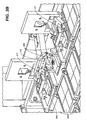
- FIG. 3B is a view of two units 317 that include the fluid control system and the detection system.
- FIG. 3B also shows a priming station 319 that is used to begin the flow of material through the microchannels of chip 204.
- Microfluidic chips are often primed with gel, buffer or another such material.
- Chip 204 is then placed in one of the two units 317, wherein the desired operation is performed on the chip 204 by the controlled flow of the material through the chip and the results determined by the detection system.
- the apparatus 300 of FIG. 3A may also include a washing or flushing system (not shown), where chip 204 and/or the liquid handling system can be flushed and/or a shaking system, whereby the chip is shaken and any materials thereon are mixed or stirred.
- a washing or flushing system not shown
- chip 204 and/or the liquid handling system can be flushed and/or a shaking system, whereby the chip is shaken and any materials thereon are mixed or stirred.
- Fig. 3B shows a chip 304 positioned in units 317.
- Chips 304 include a chip substrate and a mount. However, a chip 204 without a mount may be used instead, as discussed below in greater detail.
- electrodes positioned in a hinged lid of units 317 are lowered to engage reservoirs of a pre-positioned microfluidic chip.
- the fluid control system and detection system may be positioned on deck 302 in other ways.
- these features are disposed in head 306, which moves with respect to deck 302, such that each feature can access the chip 204 from above.
- a liquid handling device is also positioned on deck 302 and head 306 functions merely as a chip handling system to move chip 204 from the station or stations occupied by the liquid handling system to the station or stations occupied by fluid control system and detection systems.
- FIG. 4A shows an apparatus 400, which includes at least the fluid control system and the detection system, located within a housing 433.
- the apparatus 400 includes a deck 402 onto which a microfluidic chip 204 has been placed.
- the chip 204 is positioned on a moving conveyor 432, which delivers the chip 204 in the direction indicated by arrow 434 into and out of housing 433.
- conveyor 432 may move the chip out of housing 433 in a direction opposite where it entered, so that the chip may be disposed into a receptacle 436.
- the embodiment shown in FIG. 4A is particularly useful for disposable microfluidic chips 204 that are not intended to be resused. It is intended, however, that apparatus 400 may be used with either reusable or disposable microfluidic chips 204.
- Apparatus 400 of the present invention does not necessarily incorporate a liquid handling system.
- a liquid handling system may act upon a microfluidic chip 204 while it is positioned on deck 402, outside of housing 433, as shown in FIG. 4A .
- liquids may be supplied by hand to chip 204, or by some combination thereof.
- a liquid handling system may be integrated into apparatus 400, such as by having deck 402 be a station in a liquid handling system. The in and out movement of conveyor 432 allows a chip, for example, to be loaded with material on deck 402, moved into housing 433 to be primed by the fluid control system, moved back to deck 402 to reload with sample material, and moved again into housing 433 for processing.
- FIG. 4B shows a top view of the apparatus 400, showing the placement of chip 204 on deck 402 and within housing 433.
- FIG. 4B also shows the size of the apparatus relative to a conventional 96-well microliter plate A. It is intended that the apparatus 400 have the same size footprint as conventional microtiter plate A. Since the size of the apparatus 400 is roughly the dimensions of microliter plate A, it may be positioned to occupy one or more of the universal stations 320 in an apparatus 300 such as that shown in FIG. 3A , which integrates a liquid handling system therein. In other words, apparatus 400 would replace the unit 317, shown in FIG. 3A .
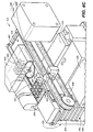
- FIG. 4C shows a schematic perspective view of the working parts of the apparatus 400, which are enclosed in a housing, such as housing 433 of FIG. 4A .
- FIG. 4C shows chip 204 positioned on deck 402. In this position, chip 204 is accessible to a liquid handling system, if desired.
- apparatus 400 may have a deck that slides into and out of housing 433, similarly to a CD player sliding in an out of a dashboard car CD player.
- Apparatus 400 includes an upper hood 440.
- the upper hood 440 includes a fluid control system, shown in phantom in FIG. 4C as electrode array 444.
- the lift arrangement 446 includes a hydraulic or pneumatic actuator, such as a motor 445 and a platform 447.
- platform 447 When actuated, platform 447 is hydraulically or pneumatically extended in a vertical direction, lifting the chip 204 off deck 402.
- Platform 447 may also be hydraulically or pneumatically retracted to reposition chip 204 on deck 402.
- chip 204 engages the electrodes 444 of the fluid control system located in the upper hood 440.
- the fluid control system only operates upon chip 204 when the chip is pressed against it.
- upper hood 440 may instead move in a vertical direction to bring the fluid control system into contact with chip 204.
- a hydraulic i or pneumatic lifting device may be positioned in the upper hood 440, such that the device pulls the chip 204 toward the electrode array 444 rather than pushing from beneath chip 204. Because upper hood 440 is positioned above chip 204, a variety of fluid control devices are easily substituted for each other.
- a detection system may either be disposed in the upper hood 440 along with the fluid control system, or it may be integrated within the lift arrangement 446, such as incorporated as part of platform 447.
- the center of platform 447 includes an optical detector 443 as part of a detection system.
- Platform 447 may also include a heating and/or cooling system, since the viscosity of fluids moving through microchannels is greatly affected by temperature changes.
- the heating and/or cooling system may also include thermocouples for measuring the temperature of fluids in microchannels and a temperature control system.
- platform 447 may incorporate an optical alignment system, such at that discussed in detail below with respect to FIG. 11.
- Apparatus 400 includes a chip handling system that features conveyor 432 to move chip 204 across deck 402.
- Conveyor 432 includes a motor 450 that rotates at least one of a pair of spindles 448 to move a belt 449.
- Spindles 448 may also be pulleys, gears, or other devices for moving a belt 449.
- Conveyor 432 also includes at least one car 451 attached to the belt 449.
- car 451 includes a rod 452 that engages a notch 409 in chip 204, to move chip 204 along deck 402.
- FIG. 5A shows another embodiment of a chip handling system that could be used in apparatus 400, which includes a conveyer 532a having a belt 549 and spindles 548, one or both of which are rotated by a motor 550. Attached to belt 549 is car 551, into which chip 204 is positioned, such that it is pushed along belt 549 from the sides of chip 204 rather than from a notch in the middle of the chip, as shown in FIG. 4C .
- conveyor 432 may use rollers instead of spindles 448 and belt 449 to move a chip 204.
- FIG. 5A shows another embodiment of a chip handling system that could be used in apparatus 400, which includes a conveyer 532a having a belt 549 and spindles 548, one or both of which are rotated by a motor 550. Attached to belt 549 is car 551, into which chip 204 is positioned, such that it is pushed along belt 549 from the sides of chip 204 rather than from a notch in the middle of
- a conveyor 532b may consist of two belts 549a and 549b for transporting the chip 204 into and out of the housing 433 and positioning chip 204 on platform 447.
- belt 549a is positioned under one side of chip 204
- belt 549b is positioned under the opposite side of chip 204, such that platform 447 has access to a central area of chip 204 between belts 549a and 549b to lift it.
- conveyor 532b of FIG. 5B does not require a car to aid in moving chip 204 along deck 402.
- conveyor 532b may use rollers instead of spindles 548 and belts 549a/549b to move a chip 204.
- FIG. 4C shows a stack 435 of chips 204.
- microfluidic chips 204 can be processed rapidly and repeatedly without having to manually load and unload each chip 204.
- FIG. 4C also shows a bucket 465, into which is inserted a cartridge 460 holding stack 435 of chips 204.
- microfluidic chips 204 are not packaged separately, but are instead packaged in stacks 435 that are stored in cartridges 460.
- FIG. 6A shows an example of a cartridge 660 with chips 204 housed therein.
- Cartridge 660 also includes a lid 662, which may be either automatically lifted by an apparatus of the present invention when a new chip is desired or which may have a slot 663 through which each chip 204 is accessed.
- stack 435 could be shrink-wrapped and shipped without an exterior cartridge. Chips may be shipped in a pre-primed condition.
- stack 435 of chips may be loaded with an electrophoresis gel or loaded with a dry material, such as a particular reagent, which can subsequently be reconstituted prior to use.
- chips may also be stacked and packaged dry, where the apparatus of the present invention includes automated priming of the chips.
- FIG. 5A further shows how stack 435 may be biased upwards by a spring 555, such that as chips 204 are removed from the stack, a new chip 204 is pushed up to the deck 402 ready perform the next analysis.
- stack 435 may be lifted by a second hydraulic or pneumatic lift device, which includes a platform 666 and a piston 667 wherein the platform is inserted into a bottom end 669 of cartridge 660 to access the chips.
- a cartridge 660a as shown in FIG. 6B , may have an opening 668 at a bottom end 669 to be accessed by the hydraulic or pneumatic lift device.
- the cartridge 660a is configured to house microfluidic chips 304 that utilize a plastic mount 627.
- mounts 627 may have the same dimensions as a microtiter plate, such that cartridge 660a may fit in a universal station 320 in apparatus 300 in FIG. 3A .
- a cartridge with an opening 668 in a bottom end 669 may also be positioned above a deck 402. As such, gravity causes the next chip 204 to fall onto deck 402 when a bottom chip 204 is removed.
- Bucket 436 may be provided for disposing of chips 204 after they have been processed.
- Bucket 436 may also include an empty cartridge 461, which is filled by the processed chips as they move along the conveyor 432, such that human contact need only occur with a cartridge and not the actual chips.
- bucket 436 may include a washing or flushing system to clean the processed chips, such that chips may be easily reused.
- bucket 436 may be connected with bucket 465 via a U-shaped tunnel running underneath the apparatus (not shown). In this embodiment, once a chip falls into bucket 436 and is washed or flushed, the chip is conveyed by another chip handling system so as to be restacked, for example from the bottom, in bucket 465. Constantly recycling chips in this manner provides constant access to fresh chips without requiring new cartridges for bucket 465.
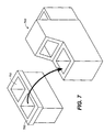
- FIG. 7 shows yet another alternative apparatus 700, which is identical to that of apparatus 400 except that apparatus 700 includes a removable deck 702.
- Deck 702 includes two or more buckets 765 for storing more than one cartridge of microfluidic chips 204.
- apparatus 700 may include multiple fluid control systems, multiple detection systems and optionally multiple liquid handling systems, in order to process multiple chips 204 at the same time.
- FIG. 8 shows a control unit 890 connected via a cable 891 to an apparatus 800 of the present invention, similar to apparatus 400 discussed above with respect to FIG. 4C .
- Control unit 890 may include electronics, power supply, pumps or other pressure controls for the fluid control device, temperature controls for heating or cooling systems of apparatus 800 and other control and operation features, such as for the detection system and liquid handling devices. Further, control unit 890 may include any necessary software and a processor including programming for the various components described above.
- an input device such as a mouse, display and/or keyboard
- control unit 890 is connected to control unit 890, such that a user can customize the particular procedures prior to and during the processing of a microfluidic chip.
- software will function with the detection system and/or liquid handling system in order to produce real-time feedback and display of data.
- data may be made available through an output device (not shown), which is in communication with control unit 890, and which may take the form of a printer, an ethernet connection, a floppy disk or CD-ROM drive, a monitor or other visual display device.
- each of the features of control unit 890 may be integrated into the apparatus 800 itself. However, having an external control unit has the advantage that the apparatus 800 may be made smaller, such as to match the size of the footprint of 96-well microtiter plate A, as discussed above.
- Control unit 890 may also be a universal control unit. As such, control unit 890 may be used with a variety of microfluidic chip processing apparatuses, which may function in different ways or be particularly designed for specific chemical or biological analyses.
- a chip 204, as shown in FIG. 2 , for use with an apparatus of the present invention may not require the plastic mount 127 shown in FIG. 1 .
- Accurate liquid handling and the reduction of human interaction makes the plastic mount 127 unnecessary.
- manufacturing time and parts are reduced, creating more efficient manufacturing, packaging and storing of microfluidic chips 204.
- mount 127 there are further advantages to removing mount 127. For example, because there is no adhesive used to attach the substrate to the mount, it is easier to determine the shelf life of the chip. Further, potential dye interactions with the mount are potentially eliminated.
- microfluidic chip 204 can be washed and/or primed at the point of use by apparatus 300/400, the chips can be stored or shipped dry for improved aging and lifetime, as well as reduced shipping and storage costs. Also, polymer mounts and adhesives are known to contaminate samples, which could make some conventional chips 104 unsuitable for use with mass spectrometers. However, without mount 127, one possible impediment to interfacing chip 204 with a mass spectrometer is eliminated.
- microfluidic chips 204 are often made several at a time on a glass, silica or plastic wafer 970.
- wafer 970 is diced to form individual chips 204.
- an apparatus such as apparatus 300 and 400 described in detail above, may act upon more than one chip 204 at a time by acting on a undiced wafer 970.
- an undiced wafer 970 may occupy a universal station 320 of the apparatus 300 of FIG. 3A .
- an undiced wafer 970 rather than a single chip may be transported by conveyer 432 in apparatus 400 of FIG. 4C .
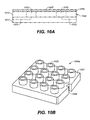
- FIG. 10A shows yet another microfluidic chip 1004 that is suitable for use in an apparatus of the present invention.
- Chip 1004 is similar to chip 204 of FIGs. 2A and 2B in that it has a first plate 1012 including a microchannel 1013 and a second plate 1014 having a reservoir 1015 bored therein.
- Chip 1004 also includes a film 1075 adhered to a surface 1007 of second plate 1014. Film 1075 covers at least reservoirs 1015, and may cover the entire chip 204, as shown in FIG. 10A .
- Film 1075 is a pierceable film, which can be pierced by a cannula or tip of a liquid handling device or by the application of heat, e.g. IR. As such, the film 1075 is pierced at the point when the material is added to the reservoir(s) 1015, forming only a very small hole accessing reservoir(s) 1015. Thus, evaporation from reservoir(s) 1015 is minimized. Also, film 1075 maybe a self-sealing film, such as a split septum, such that a small piercing for the purpose of filling reservoir 1015 may be resealed when the tip or cannula of a liquid handling device is removed.
- a self-sealing film such as a split septum
- film 1075 may provide electrical isolation between reservoirs 1015 that are located close together. For example, if electrodes engage chip 1004 as part of the fluid control system, the electrode will also pierce film 1075 in more than one reservoir 1015 location. As such, the film 1075 will act as an insulator between adjacent electrodes. As an alternative, concentric trenches may be partically etched into the second plate 1014 to increase the path length and thus the electrical impedance from reservoir to reservoir. Still further, the film 1075 may serve as a gasket for pressurized priming and washing of chip 1004.
- FIG. 10B shows yet another microfluidic chip 1004a of the present invention that includes a mount 1027. Since a chip 1004a that is used in an apparatus of the present invention does not require human handling, mount 1027 may be roughly the size of the microfluidic chip itself, and thus much smaller than a conventional mount 127, shown in FIG. 1 . Mount 1027 includes wells 1028 to aid in the application of materials to chip 1004a by either a liquid handling system or a human operator. Further, mount 1027 provides an external location for a notch 1009 to be used for a car of a conveyor to engage the chip. Thus, such a notch 1009 need not be made in the microfluidic chip itself.
- An apparatus 300/400 of the present invention may also include an alignment system to ensure that a liquid handling system, fluid control system or the detection system is properly aligned with a particular reservoir of a microfluidic chip.
- An example of an alignment system 1180 is shown in an exploded view in FIGs. 11A and 11B.
- reservoirs 1115 of a microfluidic chip 1104 are formed from non-opaque holes in a generally opaque second plate 1114, which is bonded to a transparent first plate 1112. Therefore, visible emission of light from a source 1125 will only be visible from an optical sensor 1126, when the light is positioned directly below a reservoir 1115 of the chip 1104.
- optical sensor 1126 can detect when it is properly aligned with reservoir 1115, and when reservoir 1115 is properly positioned on deck 1102. Once one reservoir is detected, the locations of all additional reservoirs may be computed. Larger multichip wafers 970, such as discussed above in FIG. 9 , reduce the amount of alignment necessary. FIG. 11A shows proper alignment of chip 1104, while FIG. 11B shows an improper alignment. A similar alignment system is described in U.S. Patent No. 6,592,825 , which is incorporated herein by reference in its entirety. Other types of sensors, as would be apparent to one skilled in the relevant art, may be used in a similar manner to indicate proper alignment of a microfluidic chip in an apparatus of the present invention.
- Embodiments of the present invention also include methods for processing a microfluidic chip using an apparatus in accordance with the present invention.
- one method includes a first step of providing an apparatus, as discussed above that includes at least a chip handling system, a fluid control system, and a detection system, and at least one microfluidic chip, which may be provided in a cartridge or as part of an undiced wafer. Further, a sample material must be loaded onto the microfluidic chip, such as by the use of an optional liquid handling device.
- the apparatus is programmed to control the flow of the sample material through the microfluidic chip in a predetermined arrangement via the fluid control system, and to detect data from an assay at a predetermined location along a microchannel of the microfluidic chip via the detection system, as discussed above with respect to the figures.
Landscapes
- Chemical & Material Sciences (AREA)
- Health & Medical Sciences (AREA)
- Analytical Chemistry (AREA)
- General Health & Medical Sciences (AREA)
- Immunology (AREA)
- Biochemistry (AREA)
- Life Sciences & Earth Sciences (AREA)
- General Physics & Mathematics (AREA)
- Physics & Mathematics (AREA)
- Pathology (AREA)
- Dispersion Chemistry (AREA)
- Clinical Laboratory Science (AREA)
- Chemical Kinetics & Catalysis (AREA)
- Hematology (AREA)
- Automatic Analysis And Handling Materials Therefor (AREA)
- Physical Or Chemical Processes And Apparatus (AREA)
Applications Claiming Priority (2)
| Application Number | Priority Date | Filing Date | Title |
|---|---|---|---|
| US57277204P | 2004-05-21 | 2004-05-21 | |
| EP05755000.6A EP1756586B1 (fr) | 2004-05-21 | 2005-05-20 | Système automatique de manipulation de dispositifs microfluidiques |
Related Parent Applications (2)
| Application Number | Title | Priority Date | Filing Date |
|---|---|---|---|
| EP05755000.6A Division EP1756586B1 (fr) | 2004-05-21 | 2005-05-20 | Système automatique de manipulation de dispositifs microfluidiques |
| EP05755000.6A Division-Into EP1756586B1 (fr) | 2004-05-21 | 2005-05-20 | Système automatique de manipulation de dispositifs microfluidiques |
Publications (3)
| Publication Number | Publication Date |
|---|---|
| EP2093571A2 true EP2093571A2 (fr) | 2009-08-26 |
| EP2093571A3 EP2093571A3 (fr) | 2009-09-02 |
| EP2093571B1 EP2093571B1 (fr) | 2014-07-09 |
Family
ID=34971415
Family Applications (2)
| Application Number | Title | Priority Date | Filing Date |
|---|---|---|---|
| EP09002994.3A Expired - Lifetime EP2093571B1 (fr) | 2004-05-21 | 2005-05-20 | Système automatique pour la manipulation des dispositifs microfluidiques |
| EP05755000.6A Expired - Lifetime EP1756586B1 (fr) | 2004-05-21 | 2005-05-20 | Système automatique de manipulation de dispositifs microfluidiques |
Family Applications After (1)
| Application Number | Title | Priority Date | Filing Date |
|---|---|---|---|
| EP05755000.6A Expired - Lifetime EP1756586B1 (fr) | 2004-05-21 | 2005-05-20 | Système automatique de manipulation de dispositifs microfluidiques |
Country Status (6)
| Country | Link |
|---|---|
| US (2) | US8496875B2 (fr) |
| EP (2) | EP2093571B1 (fr) |
| CN (1) | CN101006344B (fr) |
| AU (1) | AU2005246404A1 (fr) |
| CA (1) | CA2567537A1 (fr) |
| WO (1) | WO2005114223A2 (fr) |
Cited By (3)
| Publication number | Priority date | Publication date | Assignee | Title |
|---|---|---|---|---|
| US9475025B2 (en) | 2011-12-29 | 2016-10-25 | General Electric Company | Microfluidic handling system |
| WO2021071490A1 (fr) * | 2019-10-10 | 2021-04-15 | Hewlett-Packard Development Company, L.P. | Cassettes de distribution pour distributeurs microfluidiques |
| US11298701B2 (en) | 2018-11-26 | 2022-04-12 | King Instrumentation Technologies | Microtiter plate mixing control system |
Families Citing this family (68)
| Publication number | Priority date | Publication date | Assignee | Title |
|---|---|---|---|---|
| US6048734A (en) | 1995-09-15 | 2000-04-11 | The Regents Of The University Of Michigan | Thermal microvalves in a fluid flow method |
| US6692700B2 (en) | 2001-02-14 | 2004-02-17 | Handylab, Inc. | Heat-reduction methods and systems related to microfluidic devices |
| US7323140B2 (en) | 2001-03-28 | 2008-01-29 | Handylab, Inc. | Moving microdroplets in a microfluidic device |
| US7829025B2 (en) | 2001-03-28 | 2010-11-09 | Venture Lending & Leasing Iv, Inc. | Systems and methods for thermal actuation of microfluidic devices |
| CA2527342A1 (fr) * | 2003-06-05 | 2004-12-16 | Bioprocessors Corp. | Systeme et procede destines a une automatisation |
| EP1654066B1 (fr) | 2003-07-31 | 2014-11-12 | Handylab, Inc. | Traitement d'echantillons contenant des particules |
| EP2345739B8 (fr) | 2004-05-03 | 2016-12-07 | Handylab, Inc. | Dispositif microfluidique permettant de traiter des échantillons contenant un polynucléotide |
| US8852862B2 (en) | 2004-05-03 | 2014-10-07 | Handylab, Inc. | Method for processing polynucleotide-containing samples |
| GB0502556D0 (en) * | 2005-02-08 | 2005-03-16 | Lab901 Ltd | Analysis instrument |
| US20060246493A1 (en) * | 2005-04-04 | 2006-11-02 | Caliper Life Sciences, Inc. | Method and apparatus for use in temperature controlled processing of microfluidic samples |
| EP1963480A2 (fr) * | 2005-12-08 | 2008-09-03 | Protein Discovery, Inc. | Procedes et dispositifs pour la concentration et le fractionnement d'analytes pour analyse chimique |
| US11806718B2 (en) | 2006-03-24 | 2023-11-07 | Handylab, Inc. | Fluorescence detector for microfluidic diagnostic system |
| US9040288B2 (en) | 2006-03-24 | 2015-05-26 | Handylab, Inc. | Integrated system for processing microfluidic samples, and method of using the same |
| US7998708B2 (en) | 2006-03-24 | 2011-08-16 | Handylab, Inc. | Microfluidic system for amplifying and detecting polynucleotides in parallel |
| US10900066B2 (en) | 2006-03-24 | 2021-01-26 | Handylab, Inc. | Microfluidic system for amplifying and detecting polynucleotides in parallel |
| WO2008030433A2 (fr) * | 2006-09-06 | 2008-03-13 | Canon U.S. Life Sciences, Inc. | Configuration de modèle de puce et de cartouche permettant de réaliser des analyses microfluidiques |
| WO2008060604A2 (fr) | 2006-11-14 | 2008-05-22 | Handylab, Inc. | Système microfluidique utilisé pour amplifier et détecter des polynucléotides en parallèle |
| WO2008061165A2 (fr) | 2006-11-14 | 2008-05-22 | Handylab, Inc. | Cartouche microfluidique et son procédé de fabrication |
| DE102006057300A1 (de) * | 2006-12-05 | 2008-06-19 | Siemens Ag | Anordnung zur Aufbereitung einer Mehrzahl von Proben für eine Analyse |
| US7863035B2 (en) * | 2007-02-15 | 2011-01-04 | Osmetech Technology Inc. | Fluidics devices |
| WO2008139415A1 (fr) * | 2007-05-14 | 2008-11-20 | Koninklijke Philips Electronics N.V. | Dispositif microfluidique et procédé de fonctionnement d'un dispositif microfluidique |
| US8133671B2 (en) | 2007-07-13 | 2012-03-13 | Handylab, Inc. | Integrated apparatus for performing nucleic acid extraction and diagnostic testing on multiple biological samples |
| ES2648798T3 (es) | 2007-07-13 | 2018-01-08 | Handylab, Inc. | Materiales de captura de polinucleótidos y métodos de utilización de los mismos |
| US8287820B2 (en) | 2007-07-13 | 2012-10-16 | Handylab, Inc. | Automated pipetting apparatus having a combined liquid pump and pipette head system |
| US8182763B2 (en) | 2007-07-13 | 2012-05-22 | Handylab, Inc. | Rack for sample tubes and reagent holders |
| US9618139B2 (en) | 2007-07-13 | 2017-04-11 | Handylab, Inc. | Integrated heater and magnetic separator |
| US9186677B2 (en) | 2007-07-13 | 2015-11-17 | Handylab, Inc. | Integrated apparatus for performing nucleic acid extraction and diagnostic testing on multiple biological samples |
| US8105783B2 (en) | 2007-07-13 | 2012-01-31 | Handylab, Inc. | Microfluidic cartridge |
| US20090136385A1 (en) | 2007-07-13 | 2009-05-28 | Handylab, Inc. | Reagent Tube |
| USD621060S1 (en) | 2008-07-14 | 2010-08-03 | Handylab, Inc. | Microfluidic cartridge |
| US8016260B2 (en) | 2007-07-19 | 2011-09-13 | Formulatrix, Inc. | Metering assembly and method of dispensing fluid |
| US7909424B2 (en) * | 2007-07-31 | 2011-03-22 | Hewlett-Packard Development Company, L.P. | Method and system for dispensing liquid |
| USD618820S1 (en) | 2008-07-11 | 2010-06-29 | Handylab, Inc. | Reagent holder |
| USD787087S1 (en) | 2008-07-14 | 2017-05-16 | Handylab, Inc. | Housing |
| US8100293B2 (en) | 2009-01-23 | 2012-01-24 | Formulatrix, Inc. | Microfluidic dispensing assembly |
| US8354080B2 (en) * | 2009-04-10 | 2013-01-15 | Canon U.S. Life Sciences, Inc. | Fluid interface cartridge for a microfluidic chip |
| WO2010126897A1 (fr) * | 2009-04-27 | 2010-11-04 | Protein Discovery, Inc. | Systèmes et procédés à filtres réjecteurs électrophorétiques programmables |
| US8818860B2 (en) * | 2009-09-29 | 2014-08-26 | At&T Intellectual Property I, L.P. | Prioritized distribution of offer information |
| US8772016B2 (en) * | 2009-11-13 | 2014-07-08 | Pacific Biosciences Of California, Inc. | Sealed chip package |
| DE102010015161B4 (de) | 2010-04-16 | 2014-03-13 | Technische Universität Dresden | Mikrofluidiksystem und Verfahren zu dessen Betreiben |
| US9962692B2 (en) | 2010-08-31 | 2018-05-08 | Canon U.S. Life Sciences, Inc. | Methods, devices, and systems for fluid mixing and chip interface |
| US8951781B2 (en) | 2011-01-10 | 2015-02-10 | Illumina, Inc. | Systems, methods, and apparatuses to image a sample for biological or chemical analysis |
| CN106190806B (zh) | 2011-04-15 | 2018-11-06 | 贝克顿·迪金森公司 | 扫描实时微流体热循环仪和用于同步的热循环和扫描光学检测的方法 |
| USD692162S1 (en) | 2011-09-30 | 2013-10-22 | Becton, Dickinson And Company | Single piece reagent holder |
| DK2761305T3 (da) | 2011-09-30 | 2017-11-20 | Becton Dickinson Co | Forenet reagensstrimmel |
| WO2013067202A1 (fr) | 2011-11-04 | 2013-05-10 | Handylab, Inc. | Dispositif de préparation d'échantillons de polynucléotides |
| DK2810080T3 (da) | 2012-02-03 | 2024-06-17 | Becton Dickinson Co | Eksterne filer til fordeling af molekylære diagnostiske tests og bestemmelse af kompatabilitet imellem tests |
| EP3285062B1 (fr) | 2012-02-29 | 2019-08-07 | Fluidigm Corporation | Procédés, systèmes et dispositifs pour la capture de cellules isolées multiples et le traitement à l'aide de produits microfluidiques |
| US20150093786A1 (en) * | 2013-09-27 | 2015-04-02 | Eppendorf Ag | Laboratory apparatus and method of using a laboratory apparatus |
| US9399216B2 (en) * | 2013-12-30 | 2016-07-26 | General Electric Company | Fluid transport in microfluidic applications with sensors for detecting fluid presence and pressure |
| CN104267201B (zh) * | 2014-09-26 | 2016-03-30 | 国家纳米科学中心 | 一种自动化单抗筛选机 |
| USD800335S1 (en) * | 2016-07-13 | 2017-10-17 | Precision Nanosystems Inc. | Microfluidic chip |
| WO2018061771A1 (fr) * | 2016-09-27 | 2018-04-05 | テルモ株式会社 | Ensemble dispositif de mesure de composant et puce de mesure de composant |
| JP2019028021A (ja) * | 2017-08-03 | 2019-02-21 | アークレイ株式会社 | 分析デバイス |
| EP3454064B1 (fr) * | 2017-09-08 | 2020-11-11 | F. Hoffmann-La Roche AG | Système de positionnement de portoir |
| WO2019127131A1 (fr) * | 2017-12-27 | 2019-07-04 | 深圳达闼科技控股有限公司 | Appareil de détection raman auxiliaire et dispositif et procédé de détection raman |
| US12201979B2 (en) | 2018-04-21 | 2025-01-21 | International Business Machines Corporation | Simple flow control for microfluidic devices |
| EP3784396B1 (fr) * | 2018-04-26 | 2024-10-02 | Diversey, Inc. | Système de réservoir intelligent |
| CN113260847B (zh) * | 2018-08-23 | 2025-03-07 | 上海宜晟生物科技有限公司 | 测定板、分离片、过滤器以及样品沉积标志 |
| US11841374B2 (en) * | 2019-06-27 | 2023-12-12 | Mjnn Llc | Laboratory automation system implementing efficient path for material and lab ware transfers |
| AU2020361681A1 (en) | 2019-10-10 | 2022-05-05 | 1859, Inc. | Methods and systems for microfluidic screening |
| CN111650168B (zh) * | 2020-06-24 | 2024-11-26 | 深圳市国赛生物技术有限公司 | 全自动微流控分析仪 |
| US11753245B1 (en) | 2020-11-10 | 2023-09-12 | Express Scripts Strategic Development, Inc. | Pharmaceutical container holder |
| AU2021400519A1 (en) * | 2020-12-15 | 2023-07-06 | Quantum-Si Incorporated | Systems and methods for chip regeneration |
| CN113546701B (zh) * | 2021-07-26 | 2022-06-24 | 绿叶诊断产品技术(广东)有限公司 | 一种检测装置及检测方法 |
| JP7679763B2 (ja) * | 2021-12-21 | 2025-05-20 | 信越化学工業株式会社 | マイクロ流路デバイス用合成石英ガラス基板、並びに合成石英ガラス製マイクロ流路デバイスおよびその製造方法 |
| WO2025126086A1 (fr) * | 2023-12-11 | 2025-06-19 | Aufbau Medical Innovations Ltd. | Systèmes, dispositifs et procédés d'analyse microfluidique de fluides |
| EP4644908B1 (fr) | 2024-04-30 | 2026-07-22 | QIAGEN GmbH | Appareil de traitement, kit et procédé de traitement d'au moins un dispositif microfluidique |
Citations (2)
| Publication number | Priority date | Publication date | Assignee | Title |
|---|---|---|---|---|
| US5858195A (en) | 1994-08-01 | 1999-01-12 | Lockheed Martin Energy Research Corporation | Apparatus and method for performing microfluidic manipulations for chemical analysis and synthesis |
| US6592825B2 (en) | 1996-05-31 | 2003-07-15 | Packard Instrument Company, Inc. | Microvolume liquid handling system |
Family Cites Families (38)
| Publication number | Priority date | Publication date | Assignee | Title |
|---|---|---|---|---|
| US4187077A (en) * | 1978-06-05 | 1980-02-05 | Eastman Kodak Company | Container with article positioning element for dispensing reagent coated slides to an automated analyzer |
| US4190420A (en) * | 1978-06-05 | 1980-02-26 | Eastman Kodak Company | Container for dispensing articles to an automated analyzer |
| US4971514A (en) * | 1988-11-14 | 1990-11-20 | Prolic Sa | Stacking device for plate-like objects, in particular titer plates or the like |
| DE69331861T2 (de) * | 1992-01-16 | 2002-08-29 | Fuji Photo Film Co., Ltd. | Chemisches Analysesystem |
| US5534224A (en) * | 1993-07-16 | 1996-07-09 | Fuji Photo Film Co., Ltd. | Chemical analysis film cartridge |
| JP3295550B2 (ja) * | 1994-09-16 | 2002-06-24 | 富士写真フイルム株式会社 | 飛出し防止用封止具を備えた乾式分析フィルム用カートリッジ |
| US5674047A (en) * | 1995-07-13 | 1997-10-07 | Chiron Diagnostics Corporation | Loading mechanism for probe tip tray |
| CN1173776C (zh) * | 1996-06-28 | 2004-11-03 | 卡钳技术有限公司 | 在微规模流体性设备里的高通过量的筛选分析系统 |
| US5985214A (en) * | 1997-05-16 | 1999-11-16 | Aurora Biosciences Corporation | Systems and methods for rapidly identifying useful chemicals in liquid samples |
| US6902703B2 (en) * | 1999-05-03 | 2005-06-07 | Ljl Biosystems, Inc. | Integrated sample-processing system |
| US6838051B2 (en) * | 1999-05-03 | 2005-01-04 | Ljl Biosystems, Inc. | Integrated sample-processing system |
| US6251343B1 (en) * | 1998-02-24 | 2001-06-26 | Caliper Technologies Corp. | Microfluidic devices and systems incorporating cover layers |
| US6132685A (en) * | 1998-08-10 | 2000-10-17 | Caliper Technologies Corporation | High throughput microfluidic systems and methods |
| EP0994355A1 (fr) * | 1998-09-23 | 2000-04-19 | Randox Laboratories Ltd. | Appareil pur traitement d'un dispositif d'essai |
| US6498497B1 (en) * | 1998-10-14 | 2002-12-24 | Caliper Technologies Corp. | Microfluidic controller and detector system with self-calibration |
| WO2000035260A1 (fr) | 1998-12-07 | 2000-06-15 | Matsushita Electric Industrial Co., Ltd. | Procede de fabrication d'un substrat ceramique |
| WO2000050247A1 (fr) | 1999-02-25 | 2000-08-31 | Genicom Corporation | Reglage de l'espacement d'impression pour un dispositif d'impression |
| US7244396B2 (en) * | 1999-04-06 | 2007-07-17 | Uab Research Foundation | Method for preparation of microarrays for screening of crystal growth conditions |
| US6193102B1 (en) * | 1999-04-30 | 2001-02-27 | Incyte Pharmaceuticals, Inc. | Plate stacker apparatus |
| US6556923B2 (en) * | 2000-01-26 | 2003-04-29 | Caliper Technologies Corp. | Software for high throughput microfluidic systems |
| US6447723B1 (en) * | 2000-03-13 | 2002-09-10 | Packard Instrument Company, Inc. | Microarray spotting instruments incorporating sensors and methods of using sensors for improving performance of microarray spotting instruments |
| JP3877934B2 (ja) * | 2000-04-18 | 2007-02-07 | 富士フイルムホールディングス株式会社 | 乾式分析素子用カートリッジ |
| US6511277B1 (en) * | 2000-07-10 | 2003-01-28 | Affymetrix, Inc. | Cartridge loader and methods |
| US20020031844A1 (en) * | 2000-09-13 | 2002-03-14 | Fuji Photo Film Co., Ltd. | Biochemical analysis apparatus |
| US6398004B1 (en) * | 2000-10-27 | 2002-06-04 | Kval, Inc. | Method for dispensing and feeding articles |
| GB0117706D0 (en) * | 2001-02-16 | 2001-09-12 | Aventis Pharm Prod Inc | Automated semi-solid matrix assay and liquid handler apparatus for the same |
| US6659142B2 (en) * | 2001-03-27 | 2003-12-09 | Irm, Llc | Apparatus and method for preparing fluid mixtures |
| US6998094B2 (en) * | 2001-09-06 | 2006-02-14 | Genetix Limited | Apparatus for and methods of handling biological sample containers |
| WO2003030112A2 (fr) * | 2001-10-01 | 2003-04-10 | Frank Runnels | Distributeur d'articles plats |
| WO2003035260A1 (fr) * | 2001-10-26 | 2003-05-01 | Sequenom, Inc. | Procede et appareil a haut rendement pour chaine de traitement de manipulation d'echantillons |
| EP1403644A1 (fr) * | 2002-09-25 | 2004-03-31 | Agilent Technologies Inc. a Delaware Corporation | Dispositif d'analyse de fluides |
| CN1497716A (zh) * | 2002-10-22 | 2004-05-19 | ס�ѵ�����ҵ��ʽ���� | 用于装载半导体芯片的封装及半导体器件 |
| US20040112978A1 (en) * | 2002-12-19 | 2004-06-17 | Reichel Charles A. | Apparatus for high-throughput non-contact liquid transfer and uses thereof |
| US7275807B2 (en) * | 2002-11-27 | 2007-10-02 | Edc Biosystems, Inc. | Wave guide with isolated coupling interface |
| JP4368804B2 (ja) * | 2002-12-02 | 2009-11-18 | ユィロス・パテント・アクチボラグ | 微小流体素子の並列処理 |
| US20050238542A1 (en) * | 2004-04-22 | 2005-10-27 | Applera Corporation | Pins for spotting nucleic acids |
| AU2005252242A1 (en) * | 2004-06-07 | 2005-12-22 | Irm Llc | Dispensing systems, software, and related methods |
| US20060246575A1 (en) * | 2005-01-13 | 2006-11-02 | Micronics, Inc. | Microfluidic rare cell detection device |
-
2005
- 2005-05-20 CA CA002567537A patent/CA2567537A1/fr not_active Abandoned
- 2005-05-20 WO PCT/US2005/017892 patent/WO2005114223A2/fr not_active Ceased
- 2005-05-20 CN CN2005800212803A patent/CN101006344B/zh not_active Expired - Lifetime
- 2005-05-20 EP EP09002994.3A patent/EP2093571B1/fr not_active Expired - Lifetime
- 2005-05-20 US US11/133,943 patent/US8496875B2/en active Active
- 2005-05-20 EP EP05755000.6A patent/EP1756586B1/fr not_active Expired - Lifetime
- 2005-05-20 AU AU2005246404A patent/AU2005246404A1/en not_active Abandoned
-
2013
- 2013-07-29 US US13/953,572 patent/US9207249B2/en not_active Expired - Lifetime
Patent Citations (2)
| Publication number | Priority date | Publication date | Assignee | Title |
|---|---|---|---|---|
| US5858195A (en) | 1994-08-01 | 1999-01-12 | Lockheed Martin Energy Research Corporation | Apparatus and method for performing microfluidic manipulations for chemical analysis and synthesis |
| US6592825B2 (en) | 1996-05-31 | 2003-07-15 | Packard Instrument Company, Inc. | Microvolume liquid handling system |
Cited By (4)
| Publication number | Priority date | Publication date | Assignee | Title |
|---|---|---|---|---|
| US9475025B2 (en) | 2011-12-29 | 2016-10-25 | General Electric Company | Microfluidic handling system |
| US11298701B2 (en) | 2018-11-26 | 2022-04-12 | King Instrumentation Technologies | Microtiter plate mixing control system |
| US12168233B1 (en) | 2018-11-26 | 2024-12-17 | King Instrumentation Technologies | Microtiter plate mixing control system |
| WO2021071490A1 (fr) * | 2019-10-10 | 2021-04-15 | Hewlett-Packard Development Company, L.P. | Cassettes de distribution pour distributeurs microfluidiques |
Also Published As
| Publication number | Publication date |
|---|---|
| US8496875B2 (en) | 2013-07-30 |
| CN101006344B (zh) | 2011-07-13 |
| US20060165559A1 (en) | 2006-07-27 |
| AU2005246404A1 (en) | 2005-12-01 |
| WO2005114223A2 (fr) | 2005-12-01 |
| EP2093571B1 (fr) | 2014-07-09 |
| US9207249B2 (en) | 2015-12-08 |
| CN101006344A (zh) | 2007-07-25 |
| CA2567537A1 (fr) | 2005-12-01 |
| WO2005114223A3 (fr) | 2006-05-04 |
| US20130315781A1 (en) | 2013-11-28 |
| EP1756586A2 (fr) | 2007-02-28 |
| EP1756586B1 (fr) | 2014-07-09 |
| EP2093571A3 (fr) | 2009-09-02 |
Similar Documents
| Publication | Publication Date | Title |
|---|---|---|
| EP2093571B1 (fr) | Système automatique pour la manipulation des dispositifs microfluidiques | |
| KR101680185B1 (ko) | 시료분석용 분석장치 | |
| US10857538B2 (en) | Sample preparation system and cartridge | |
| US20020092767A1 (en) | Multiple array microfluidic device units | |
| US6905657B2 (en) | Methods and devices for storing and dispensing liquids | |
| CA2435789A1 (fr) | Systeme et cartouche de traitement d'un prelevement biologique | |
| EP2073018A1 (fr) | Dispositif d'aspiration de liquide | |
| US20020137199A1 (en) | Micro storage, reaction and detection cells and method and apparatus for use thereof | |
| US20050069462A1 (en) | Microfluidics Packaging | |
| US20050069949A1 (en) | Microfabricated Fluidic Structures | |
| JP2008509387A (ja) | マイクロ流体デバイスを流体処理デバイスと接続する装置及び方法 | |
| EP1264637B1 (fr) | Microplaquette de laboratoire et procédé pour analyse chimiques | |
| US20240279727A1 (en) | Device and method for processing biological samples | |
| JP2006329901A (ja) | 化学分析装置 | |
| EP2069800B1 (fr) | Dispositif d'analyse clinique | |
| JP2009222479A (ja) | 検査装置 | |
| EP1681571B1 (fr) | Appareil et procédé de manipulation de fluides pour analyse | |
| KR20230149808A (ko) | 화학 처리 시스템, 기기 및 샘플 카트리지 | |
| JP2006317365A (ja) | 化学分析装置 | |
| KR20260029462A (ko) | 체외 진단을 수행하기 위한 플랫폼 | |
| KR20260043563A (ko) | 샘플 용기 홀딩용 장치 및 상기 장치를 포함하는 키트 | |
| CN116963837A (zh) | 化学处理系统、仪器和样品盒 |
Legal Events
| Date | Code | Title | Description |
|---|---|---|---|
| PUAI | Public reference made under article 153(3) epc to a published international application that has entered the european phase |
Free format text: ORIGINAL CODE: 0009012 |
|
| PUAL | Search report despatched |
Free format text: ORIGINAL CODE: 0009013 |
|
| AC | Divisional application: reference to earlier application |
Ref document number: 1756586 Country of ref document: EP Kind code of ref document: P |
|
| AK | Designated contracting states |
Kind code of ref document: A2 Designated state(s): AT BE BG CH CY CZ DE DK EE ES FI FR GB GR HU IE IS IT LI LT LU MC NL PL PT RO SE SI SK TR |
|
| AK | Designated contracting states |
Kind code of ref document: A3 Designated state(s): AT BE BG CH CY CZ DE DK EE ES FI FR GB GR HU IE IS IT LI LT LU MC NL PL PT RO SE SI SK TR |
|
| 17P | Request for examination filed |
Effective date: 20100108 |
|
| AKX | Designation fees paid |
Designated state(s): AT BE BG CH CY CZ DE DK EE ES FI FR GB GR HU IE IS IT LI LT LU MC NL PL PT RO SE SI SK TR |
|
| 17Q | First examination report despatched |
Effective date: 20110606 |
|
| GRAP | Despatch of communication of intention to grant a patent |
Free format text: ORIGINAL CODE: EPIDOSNIGR1 |
|
| INTG | Intention to grant announced |
Effective date: 20131119 |
|
| GRAS | Grant fee paid |
Free format text: ORIGINAL CODE: EPIDOSNIGR3 |
|
| RBV | Designated contracting states (corrected) |
Designated state(s): DE GB |
|
| GRAA | (expected) grant |
Free format text: ORIGINAL CODE: 0009210 |
|
| AC | Divisional application: reference to earlier application |
Ref document number: 1756586 Country of ref document: EP Kind code of ref document: P |
|
| AK | Designated contracting states |
Kind code of ref document: B1 Designated state(s): DE GB |
|
| REG | Reference to a national code |
Ref country code: GB Ref legal event code: FG4D |
|
| REG | Reference to a national code |
Ref country code: DE Ref legal event code: R096 Ref document number: 602005044169 Country of ref document: DE Effective date: 20140821 |
|
| REG | Reference to a national code |
Ref country code: DE Ref legal event code: R097 Ref document number: 602005044169 Country of ref document: DE |
|
| PLBE | No opposition filed within time limit |
Free format text: ORIGINAL CODE: 0009261 |
|
| STAA | Information on the status of an ep patent application or granted ep patent |
Free format text: STATUS: NO OPPOSITION FILED WITHIN TIME LIMIT |
|
| 26N | No opposition filed |
Effective date: 20150410 |
|
| P01 | Opt-out of the competence of the unified patent court (upc) registered |
Effective date: 20230526 |
|
| PGFP | Annual fee paid to national office [announced via postgrant information from national office to epo] |
Ref country code: GB Payment date: 20240402 Year of fee payment: 20 |
|
| PGFP | Annual fee paid to national office [announced via postgrant information from national office to epo] |
Ref country code: DE Payment date: 20240326 Year of fee payment: 20 |
|
| REG | Reference to a national code |
Ref country code: DE Ref legal event code: R071 Ref document number: 602005044169 Country of ref document: DE |
|
| REG | Reference to a national code |
Ref country code: GB Ref legal event code: PE20 Expiry date: 20250519 |
|
| PG25 | Lapsed in a contracting state [announced via postgrant information from national office to epo] |
Ref country code: GB Free format text: LAPSE BECAUSE OF EXPIRATION OF PROTECTION Effective date: 20250519 |