EP2093659B1 - Vorrichtung, Verfahren und computerlesbares Medium zur Seitenbeschreibungssprachverarbeitung - Google Patents
Vorrichtung, Verfahren und computerlesbares Medium zur Seitenbeschreibungssprachverarbeitung Download PDFInfo
- Publication number
- EP2093659B1 EP2093659B1 EP09250416.6A EP09250416A EP2093659B1 EP 2093659 B1 EP2093659 B1 EP 2093659B1 EP 09250416 A EP09250416 A EP 09250416A EP 2093659 B1 EP2093659 B1 EP 2093659B1
- Authority
- EP
- European Patent Office
- Prior art keywords
- program
- data
- command
- common
- pdl
- Prior art date
- Legal status (The legal status is an assumption and is not a legal conclusion. Google has not performed a legal analysis and makes no representation as to the accuracy of the status listed.)
- Active
Links
Images


Classifications
-
- G—PHYSICS
- G06—COMPUTING OR CALCULATING; COUNTING
- G06F—ELECTRIC DIGITAL DATA PROCESSING
- G06F3/00—Input arrangements for transferring data to be processed into a form capable of being handled by the computer; Output arrangements for transferring data from processing unit to output unit, e.g. interface arrangements
- G06F3/12—Digital output to print unit, e.g. line printer, chain printer
- G06F3/1201—Dedicated interfaces to print systems
- G06F3/1223—Dedicated interfaces to print systems specifically adapted to use a particular technique
- G06F3/1237—Print job management
- G06F3/1244—Job translation or job parsing, e.g. page banding
- G06F3/1248—Job translation or job parsing, e.g. page banding by printer language recognition, e.g. PDL, PCL, PDF
-
- G—PHYSICS
- G06—COMPUTING OR CALCULATING; COUNTING
- G06F—ELECTRIC DIGITAL DATA PROCESSING
- G06F3/00—Input arrangements for transferring data to be processed into a form capable of being handled by the computer; Output arrangements for transferring data from processing unit to output unit, e.g. interface arrangements
- G06F3/12—Digital output to print unit, e.g. line printer, chain printer
- G06F3/1201—Dedicated interfaces to print systems
- G06F3/1202—Dedicated interfaces to print systems specifically adapted to achieve a particular effect
- G06F3/1211—Improving printing performance
- G06F3/1215—Improving printing performance achieving increased printing speed, i.e. reducing the time between printing start and printing end
-
- G—PHYSICS
- G06—COMPUTING OR CALCULATING; COUNTING
- G06F—ELECTRIC DIGITAL DATA PROCESSING
- G06F3/00—Input arrangements for transferring data to be processed into a form capable of being handled by the computer; Output arrangements for transferring data from processing unit to output unit, e.g. interface arrangements
- G06F3/12—Digital output to print unit, e.g. line printer, chain printer
- G06F3/1201—Dedicated interfaces to print systems
- G06F3/1202—Dedicated interfaces to print systems specifically adapted to achieve a particular effect
- G06F3/1218—Reducing or saving of used resources, e.g. avoiding waste of consumables or improving usage of hardware resources
- G06F3/122—Reducing or saving of used resources, e.g. avoiding waste of consumables or improving usage of hardware resources with regard to computing resources, e.g. memory, CPU
-
- G—PHYSICS
- G06—COMPUTING OR CALCULATING; COUNTING
- G06F—ELECTRIC DIGITAL DATA PROCESSING
- G06F3/00—Input arrangements for transferring data to be processed into a form capable of being handled by the computer; Output arrangements for transferring data from processing unit to output unit, e.g. interface arrangements
- G06F3/12—Digital output to print unit, e.g. line printer, chain printer
- G06F3/1201—Dedicated interfaces to print systems
- G06F3/1278—Dedicated interfaces to print systems specifically adapted to adopt a particular infrastructure
- G06F3/1284—Local printer device
Definitions
- aspects of the present invention relate to a device for processing a plurality of types of page description languages.
- JP HEI 4-128068A discloses an example of a device supporting a plurality of types of PDLs.
- the device disclosed in JP HEI 4-128068A is configured to have a plurality of types of page description language interpretation objects and to switch between the plurality of types of page description language interpretation objects in accordance with the type of the page description language inputted to the device.
- the device is able to support the plurality of types of page description language.
- the device in order to support the plurality of types of page description languages, the device is required to install thereon a plurality of types of PDL programs (page description language processing programs), which also requires the device to have a storage device with a large capacity for the PDLs programs.
- PDL programs page description language processing programs
- a common PDL program having a function of converting the plurality of types of page description languages into common intermediate language, and to process the common intermediate language.
- the plurality of types of page description languages are based on respective specifications, and therefore have expressive capabilities different from each other (e.g., an expressive capability for complicated gradation or a transparent process).
- a plurality of types of image formats exist. Therefore, in order to convert all of the plurality of types of page description languages into intermediate language data and to process the converted intermediate language data, a device needs to use a sophisticated program for converting the page description languages into intermediate codes. As a result, the data amount for the program increases. It should be noted that regarding processing of a page description language having a relatively poor expressing capability, use of such a sophisticated program is not desirable in regard to increase of a processing speed and the data amount for necessary programs.
- US 5,303,336 discloses a printing system including a print server in which a plurality of command processing programs associated with different printing protocols of a plurality of terminals are stored.
- the print server is responsive to an identifier identifying the type of printing protocol to select one of the command processing programs.
- aspects of the present invention are advantageous in that at least one of device, method and computer readable medium for supporting a plurality of types of page description languages while achieving reduction in memory size and increasing a processing speed is provided.
- a page description processing device a method to be implemented on a page description processing device and a computer readable medium having computer readable instructions stored thereon, which when executed by a computer functioning as a page description language processing device are configured to execute the steps of said method.
- the common codes do not correspond to all of the codes of a page description language. That is, predetermined codes selected from all the codes of the page description language are used as the common codes. Therefore, it is possible to process the page description language described only by the common codes. It is also possible to process a page description language having complicated functions while saving memory consumption. It is also possible to decrease the data amount for programs.
- the data input unit may input vector data received from an external device (e.g., a personal computer, a server, or a portable memory) to the page description language processing device.
- an external device e.g., a personal computer, a server, or a portable memory
- the term "in response to " as used herein means various conditions can be taken into consideration by using AND-condition or OR-condition.
- the term “gradation” is used.
- the intermediate language creation program storage unit stores a program for generating vector data described in an intermediate language from vector data of liner gradation described in a format of each of the plurality of types of PDLs.
- intermediate language creation program storage unit does not store a program for generating vector data described in the intermediate language from the vector data of the non-liner gradation which only a single type of PDL (or a few types of PDLs) is able to describe.
- the first judgment unit provided an affirmative judgment result
- the vector data described in the intermediate language is generated, and bitmap data is generated from the vector data.
- a program for processing a plurality of types of PDLs it is possible to share a program for generating bitmap data from the vector data of the liner gradation (intermediate language). Such a configuration makes it possible to decrease the data amount for programs.
- the first judgment unit provides a negative judgment result, and in this case vector data described in the intermediate language is not generated.
- the vector data of the non-liner gradation is converted into bitmap data without being converted into the intermediate language. Since the program for generating the vector data described in the intermediate language from the vector data of the non-linar gradation is not required, it is possible to decrease the data amount for necessary programs. According to the above described technology, it is possible to provide a device capable of processing a plurality of types of PDLs in a relatively small data amount of programs.
- the page description language processing device further comprises: a first bitmap data creation program storage unit configured to store a program having a function of generating bitmap data from the data described in the intermediate language; and a second bitmap data creation program storage unit configured to store a program having a function of generating bitmap data from the data described in a format other than the predetermined format, for each of the plurality of types of page description languages.
- the first bitmap data creation unit generates the bitmap data from the data generated by the intermediate language data creation unit in accordance with the program stored in the first bitmap data creation program storage unit; and the second bitmap data creation unit generates the bitmap data from the data described in the description format in accordance with the program stored in the second bitmap data creation program storage unit.
- the "plurality of types of page description languages" of the second bitmap creation program storage unit may be different from the "the plurality of types of page description languages" of the intermediate language creation program storage unit or may be the same as those of the intermediate language creation program storage unit. For example, if it is possible to generate the intermediate language from all the formats of predetermined PDLs to be used, the second bitmap data creation program storage unit may not store the program for generating bitmap data from the predetermined PDLs.
- the page description language processing device further comprises a third judgment unit configured to judge whether the description format corresponds to the program stored in the second bitmap data creation program storage unit.
- the second bitmap data creation unit is configured to: generate the bitmap data from the entire data received through the data input unit described in the description format in accordance with the program stored in the second bitmap data creation program storage unit in response to a fact that the first judgment unit judges that the description format describing the data inputted through the data input unit does not correspond to the program stored in the intermediate language creation program storage unit and the second judgment unit judges that the description format corresponds to the program stored in the second bitmap data creation program storage unit; and generate the bitmap data from a part of the data received through the data input unit in response to a fact that the first judgment unit judges that the description format describing the data inputted through the data input unit does not correspond to the program stored in the intermediate language creation program storage unit and the second judgment unit judges that the description format does not correspond to the program stored in the second bitmap data creation program storage unit.
- the third judgment unit provides a negative judgment result for such vector data, and bitmap data is generated from a part of the vector data (i.e., partial vector data which the device is able to interpret).
- bitmap data is generated from a part of the vector data (i.e., partial vector data which the device is able to interpret).
- the second bitmap data creation program storage unit stores a common program having a function of generating bitmap data from data described in a common format common to at least two types of page description languages.
- a common program may be used as in the case of the above described shared program. That is, regarding program stored in the intermediate language vector data creation unit, a common program may be used for generating vector data described in the intermediate language from the vector data described in a common format common to at least two types of page description languages.
- both of the first type PDL and the second type PDL can represent the same special color and formats for describing the same special color are different between the first type PDL and the second type PDL.
- a special color is converted into bitmap data after being converted into a typical color.
- a program for converting the special color described in the format of the first type PDL into a typical color and a program for converting the special color described in the format of the second type PDL into a typical color are required.
- grade and text are examples used for the purpose of easy understanding of the embodiments. The embodiments are not limited to such examples. Many PDLs are able to describe the same type of data. Fur example, many PDLs are able to describe liner gradation and text.
- vector data described in an intermediate language is generated from vector data described in PDL
- bitmap data is generated from the vector data described in the intermediate language. That is, vector data described in various types of page description languages is converted into vector data described in the intermediate language before generating bitmap data.
- vector data described in an intermediate language is generated from the liner gradation described in the first type PDL and vector data described in the same intermediate language is generated from the liner gradation described in the second type PDL.
- the same vector data described in the intermediate language is generated. Therefore, a program having a function of converting the vector data described in the intermediate language is able to generate bitmap data for each of the liner gradations of the first type PDL and the second type PDL.
- a first program for generating vector data described in the intermediate language from the gradation described in the first type PDL a second program for generating vector data described in the intermediate language from the liner gradation described in the second type PDL, and a third program for generating bitmap data from the vector data described in the intermediate language are required. That is, the third program for generating bitmap data from the vector data of the liner gradation can be used as a common program common to the first type PDL and the second type PDL for generating bitmap data.
- the program for converting the vector data (PDL) into vector data does not require a large data amount for programs.
- the data amount of the program for generating bitmap data from the vector data is larger than that of the program for converting the vector data described in PDL into vector data described in the intermediate language.
- the total data amount for programs can be decreased in comparison with the configuration of the device disclosed in JP HEI 4-128068A .
- vector data can be described in various types of formats (i.e., various types of expressive functions).
- a PDL having a format capable of describing non-iiner gradation has been proposed. That is, there exists a special format supported only by a single type PDL (or a few types of PDLs). For example, there may be a case where only the first type PDL is able to use a format describing non-liner gradation and the other type PDL (i.e. the second type PDL) is not able to describe the non-liner gradation.
- a program for generating vector data described in the intermediate language from vector data of the non-liner gradation described in the first type PDL, and a program for generating bitmap data from the vector data are required.
- the program for generating bitmap data from the vector data of one PDL can not be shared with the other PDLs because the other PDLs are not able to describe the non-liner gradation.
- the inventors of this application find a fact that it is possible to decrease the total data amount for programs by not converting a special format, which only a single type of PDL (or a few types of PDLs) supports, into the intermediate language.
- Fig. 1 is a block diagram of a printer 10 according to the example.
- the printer 10 includes a CPU 11, a ROM 12, a RAM 13, a communication I/F (interface) 14, and a print unit 15.
- the CPU 11 is able to execute a PDL processing program and an intermediate code processing program which are described later.
- the ROM 12 stores the PDL processing program and the intermediate code processing program. When these programs are executed, various types of data is written to or read from the RAM 13.
- the printer 10 receives PDL data from an external computer via the communication I/F 14. Image data is generated by executing the intermediate code processing program. The image data thus generated is then subjected to a print process by the print unit 15.
- the above described components are connected with each other via signal lines.
- Fig. 1 shows an example of a configuration of a printer. Various types of configurations can be adopted as a configuration of the printer 10.
- Fig. 2 shows a system configuration including the printer 10, a computer 20 and a router 30.
- the printer 10 is connected to the computer 20 via the router 30.
- this system data described in PDL is transmitted from the computer 20 to the printer 10.
- the programs stored in the printer 10 are classified into two types of programs including the PDL processing program and the intermediate code processing program.
- the PDL processing program has the functions of interpreting PDL data and converting it into intermediate codes (common codes and special codes).
- the intermediate code processing program has the functions of generating image data based on the intermediate codes interpreted by the PDL processing program.
- the processing of the PDL processing program and the processing of the intermediate code processing program may be executed sequentially as a series of programs.
- An image corresponding to the image data generated by the intermediate code processing program is printed through the print unit 15 of the printer 10. If the printer 10 is configured as a laser beam printer, a laser printing engine is employed as the print unit 15.
- Fig. 3 illustrates a flow of processing of the PDL processing program and the intermediate code processing program.
- the intermediate code processing program reads information which is written to the RAM 13 by the PDL processing program, and processes the read information.
- the PDL processing program obtains the PDL data (step (1)).
- the PDL processing program supports various types of PDL data.
- the PDL processing program interprets sequentially codes (commands) contained in the obtained PDL data.
- the PDL processing programs refers to a common intermediate code table stored in the RAM 13 (step (2)).
- Fig. 4 illustrates an example of the common intermediate code table.
- codes which the intermediate code processing program is able to process are stored as "common codes".
- numbers are assigned to the common codes, respectively.
- the common intermediate code table is written to the RAM 13 at predetermined timings.
- One of the codes defined as the common codes is a command for drawing letters.
- Each common code has a high degree of versatility, i.e., each common code has a high possibility of being used by a plurality of types of PDLs.
- the PDL processing program judges that a target code (a target to be interpreted) is contained in the common intermediate code table, the PDL processing program writes the common code corresponding to the target code to an intermediate code buffer (step (3)). In this case, the PDL processing program may write a number corresponding to the common code to the intermediate code buffer.
- the PDL processing program judges that the target code is not contained in the common intermediate code table, the PDL processing program writes the target code and an address of a module (hereafter, referred to as a module address) for the target code to the intermediate code buffer (steps (4), (5), and (6)).
- the module for the code has been loaded in the RAM 13.
- the PDL processing program writes the code in the intermediate code buffer as a "special code" (step (3)).
- Fig. 5 illustrates an example of a data structure of the intermediate code buffer. As shown in Fig. 5 , in the intermediate code buffer, intermediate codes converted by the PDL processing program are written sequentially. Fig. 5 illustrates that codes in the PDL data obtained in step (1) have been interpreted as "common code B" ⁇ "common code E” ⁇ "special code 1" ⁇ "special code 2" ⁇ ⁇ ⁇ "common code D”.
- Fig. 6 illustrates an example of a data structure of an intermediate code registration table.
- special data contained in the PDL data is stored in association with a module address.
- the special code processing module is written to the RAM 13 at predetermined timings.
- a code defined as a special code includes a command for representing gradation.
- the special codes are used for special purposes. Therefore, the special code does not have a high degree of versatility.
- the PDL processing program interprets the code of the obtained PDL data, and writes a result of the interpretation to the intermediate code buffer. If the PDL processing program interprets the special code, the PDL processing program writes a process module for the special code to the RAM 13. Then, the PDL processing program writes an address of the module to the intermediate code registration table. The information stored in the intermediate code registration table is used by the intermediate code processing program.
- the intermediate code processing program accesses the intermediate code buffer, and reads codes sequentially from the intermediate code buffer. If the read code is the common code, the intermediate code processing program executes a common code process module corresponding to the obtained code (steps (8), (9)). As described above, the intermediate code processing program is able to generate image data corresponding to the code (i.e., to draw an image corresponding to the image data).
- the intermediate code processing program is able to obtain a module address of the special code by referring to the intermediate code registration table (step (10)). Then, the intermediate code processing program executes the module (special code processing module) corresponding to the obtained module address (steps (11), (12)). As described above, the intermediate code processing program is able to generate image data corresponding to the code (i.e., to draw an image corresponding to the image data).
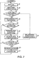
- Fig. 7 is a flowchart illustrating the PDL processing program.
- the PDL processing program is executed by the CPU 11 of the printer 10.
- the PDL processing program interprets sequentially PDL codes contained in the PDL data, and writes the common code or the special code obtained as a result of the interpretation to the intermediate code buffer.
- the CPU 11 reads a PDL code from the obtained PDL data (step S1). Then, the CPU 11 refers to the common intermediate code table to judge whether the PDL code exists in the common intermediate code table. That is, the CPU 11 judges whether the obtained code is the common code (i.e., a command for executing a common code processing module which the intermediate code processing program has) or the special code (i.e., a command for executing a module which has not been provided for the intermediate code processing program in advance).
- the common code i.e., a command for executing a common code processing module which the intermediate code processing program has
- the special code i.e., a command for executing a module which has not been provided for the intermediate code processing program in advance.
- step S4 the CPU 11 writes a corresponding intermediate code to the intermediate code buffer.
- the intermediate code buffer is secured, for example, in the RAM 13.
- the CPU 11 may secure a certain size of memory area for the intermediate code buffer, when the CPU 11 makes a judgment of "YES" at step S3 or the CPU 11 may secure a predicted amount of memory area for the intermediate code buffer at a time of starting execution of the PDL processing program.
- step S5 the CPU 11 refers to the intermediate code table to judge whether the obtained PLD code has been contained in the intermediate registration code table.
- step S7 the CPU 11 writes the obtained PDL code to the intermediate code registration table as a special code. Further, the CPU 11 writes a module address corresponding to the special code to the intermediate code registration table while associating the module address with the special code (see Fig. 6 ).
- the intermediate code registration table is secured, for example, in the RAM 13.
- the CPU 11 may secure a certain size of memory area for the intermediate code registration table each time the CPU 11 makes a judgment of "NO" at step S6, or the CPU 11 may secure a predicted amount of memory area for the intermediate code registration table at a time of starting execution of the PDL processing program.
- the code corresponding to the PDL code may be written to the RAM 13 at predetermined timing.
- the module may be written to the RAM 13 at step S7.
- step S8 if the obtained PDL code is found in the intermediate code registration table (S6: YES), control proceeds to step S8. That is, in this case, if the special code and the module address corresponding to the obtained PDL data have been stored in the intermediate code registration table, there is no necessity to newly register a PDL code in the intermediate code registration table.
- step S8 the CPU 11 writes the obtained PDL code to the intermediate code buffer as a special code.
- the CPU 11 may write an identification number identifying the special code to the intermediate code buffer.
- step S9 the CPU 11 judges whether PDL codes for one page have been interpreted. If the PDL codes for one page have been interpreted (S9: YES), control proceeds to step S10. On the other hand, if interpretation of PDL codes for one page has not been finished (S9: NO), control returns to step S1 to read a next PDL code.
- step S10 the CPU 11 executes an intermediate code process which is described later.
- step S 11 the CPU 11 releases the intermediate code buffer, the intermediate code registration table and the special module from the respective memory areas.
- Fig. 8 is a flowchart of an intermediate code process.
- the intermediate code process is executed when called from the PDL process shown in Fig. 7 .
- the CPU 11 reads intermediate codes sequentially from the intermediate code buffer, and executes the obtained intermediate code to generate image data.
- step S21 the CPU 11 reads an intermediate code from the intermediate code buffer (step S21).
- step S22 the CPU 11 judges whether the obtained code is a special code.
- the CPU 11 may make a judgment in step S22 by referring to the common intermediate code table (see Fig. 4 ). If the CPU 11 judges that the obtained intermediate code is not the special code (i.e., the intermediate code is a common code) (S22: NO), control proceeds to step S23.
- step S23 the CPU 11 executes the module corresponding to the common code to generate image data.
- the generated image data is then stored temporarily in a certain area of the RAM 13.
- the module corresponding to the common code has been loaded on the RAM 13.
- step S24 the CPU 11 accesses the intermediate code registration table (see Fig. 6 ), to determine the module address for the special code.
- step S25 the CPU 11 executes the module at the address determined in step S24 to generate image data.
- the generated image data is stored temporarily in a certain area of the RAM 13.
- step S26 the CPU 11 judges whether codes for one page have been executed. If execution for the codes for one page has not been finished (S26: NO), control returns to step S21 to read a next code. On the other hand, execution of codes for one page has been finished (S26: YES), the intermediate code process terminates. A page of image data generated as above is then passed to the print unit 15 to be printed, for example, on a sheet of paper.
- the intermediate code (the common code or the special code) is executed on the basis of a unit of PDL data.
- a memory e.g., the RAM 13
- the memory areas for the intermediate code buffer, the intermediate code registration table and the special module are released.
- Fig. 9 illustrates a situation where the memory areas have been released after execution of the process for the PDL data.
- memory areas for the intermediate code buffer, the intermediate code registration table, a special code processing module 1 and a special code process module 2 have been released.
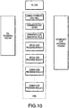
- Fig. 10 illustrates a situation where memory areas for the intermediate code buffer, the intermediate code registration table, a special code processing module 3 and a special code processing module 4 have been newly secured in the RAM 13.
- the intermediate code buffer, the intermediate code registration table, the special code processing module 3 and the special code processing module 4 are newly secured. It should be noted that contents in the intermediate code buffer and the intermediate code registration table in Fig. 10 are different from those of the intermediate code buffer and the intermediate code registration table in Fig. 3 .
- the CPU 11 repeats securing and releasing of the memory areas on the basis of a process for a page of PDL data.
- Such a configuration makes it possible to save the memory area, and thereby to effectively use memory areas.
- securing and releasing of memory areas are performed on the basis of a process for a page of PDL data
- the securing and releasing of memory areas may be performed on the basis of processes corresponding to a plurality of pages of PDL data.
- Fig. 11 illustrates memory areas in the RAM 13 in a situation where PDL data formed only by the common codes has been processed. As shown in Fig. 11 , the memory area for the intermediate code buffer is secured, but the memory areas for the intermediate code registration table and the special code processing module are not secured.
- the memory amount to be secured can be decreased.
- the CPU 11 interprets sequentially the PDL codes, and converts the PDL codes into the common codes or the special codes.
- the CPU 11 writes a special code processing module corresponding to the PDL code to a memory while associating the code with an address of the special code processing module.
- the PDL data including only the common code type it is possible to decrease the size for a memory area to be secured on a memory.
- the PDL data including the special code it is possible to secure and release a memory area for a special code processing module required for execution of the special code, on the basis of a unit of a page.
- Fig. 12 illustrates a configuration of a printer network system 102 according to the second embodiment.
- the network system 102 includes a printer 110 and a PC (personal computer) 140 which are connected to each other via a communication line 130.
- the PC 140 stores a plurality of pieces of data, and is configured to be able to instruct the printer 110 to print data files in response to a user operation.
- the PC 140 converts a data file into PDL in response to a user command and sends the data file described in PDL to the printer 110.
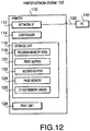
- Fig. 12 also illustrates a block diagram of the printer 110.
- the printer 110 includes a network interface 112, a controller 114, a storage unit 116, and a print unit 128.
- the network interface 112 is connected to the communication line 130 to interface the printer 110 with the PC 140. Through the communication line 130, the printer 110 is able to communicate with the PC 140.
- the controller 114 executes various processes in accordance with programs stored in the storage unit 116. The processes executed by the controller 114 are described in detail later.
- the storage unit 116 includes various types of memories including a ROM, an EEPROM, and a RAM. More specifically, the storage unit 116 includes a program memory area 118, a first buffer 120, a second buffer 122, a page memory 124 and another memory area 126.
- the program memory area 118 stores various types of programs which are described in detail later.
- the first and second buffers 120 and 122 are used in a PDL conversion process which is descried later.
- the page memory 124 stores bitmap data to be printed on a page of print medium.
- the memory area 126 stores information other than information stored in the memory areas 118, 120, 122 and 124.
- the print unit 128 includes a mechanism configured to carry a print medium and a mechanism configured to form an image on a print medium (e.g., an inkjet image formation mechanism or a laser image formation mechanism).
- the print unit 128 forms an image on a print medium in accordance with BMP data for print stored in the page memory 124.
- the printer 110 converts vector data (hereafter, frequently referred to as PDL data) described in PDL into vector data described in intermediate language (hereafter, frequently referred to as intermediate language data). Then, the printer 110 converts the intermediate language data into multiple gray scale bitmap data (hereafter, frequently referred to as BMP data), and stores the multiple gray scale bitmap data in the page memory 124.
- PDL data vector data
- intermediate language data vector data described in intermediate language
- BMP data multiple gray scale bitmap data
- Fig. 13 illustrates contents in the program memory area 118.
- the program memory area 118 includes a PDL1 program 50, a PDL2 program 60 and a PDL3 program 70.
- the PDL1 program 50 processes PDL of a first type (hereafter, referred to as a first type PDL or PDL1)
- the PDL2 program 60 processes PDL of a second type (hereafter, referred to as a second type PDL or PDL2)
- the PDL3 program 70 processes PDL of a third type (hereafter, referred to as a third type PDL).
- the program memory area 118 stores only three types of programs for processing three types of PDLs, four or more types of programs for processing four or more types of PDLs may be stored in the program memory area 118.
- the PDL1 program 50 includes programs 52, 54 and 56 each of which has a function of converting a command to another type of data.
- the programs 52, 54 and 56 are described in detail below.
- the program 52 converts a command used in PDL1 into data described in an intermediate language.
- a program for converting a command CM1 of PDL1 (PDL1-CM11) into a common intermediate language command CM 10 (A11PDL-CM10) (hereafter, referred to as "all PDL common intermediate language") which is shared among all of the types of PDLs.
- the program 54 converts a command used in PDL1 into data described an intermediate language (hereafter, referred to as "PDL1/PDL2 common intermediate language") which is common only to PDL1 and PDL2.
- PDL1/PDL2 common intermediate language an intermediate language
- Fig. 13 as an example of the program 54, a program which converts a command CM71 of PDL1 (PDL1-CM71) into a command CM70 of PDL1/2 common intermediate language (PDL1/2-CM70) is illustrated.
- the PDL2 program 60 includes programs 62, 64 and 66 each of which has a function of converting a command into another type of data.
- the program 62 converts a command used in PDL2 (e.g., PDL2-CM2) into "all PDL common intermediate language" (e.g., AllPDL-CM10).
- the program 64 converts a command used in PDL2 (e.g., PDL2-CM72) into "PDL1/2 common intermediate language” (e.g., PDL1/2-CM70).
- the program 66 converts a command used in PDL2 (e.g., PDL2-CM92) into BMP data.
- the PDL3 program includes programs 72 and 75 each of which has a function of converting a command into another type of data.
- the program 72 converts a command used in PDL 3 (e.g., PDL 3-CM13) into "all PDL common intermediate language" (e.g., AllPDL-CM10).
- the program 74 converts a command used PDL3 (e.g., PDL3-CM92) into BMP data. It should be noted that the PDL3 program 70 does not include a program which converts a command into "PDL 1 /2 common intermediate language".
- the PDL2 and PDL3 use a command CM 92 which has a common concept common to PDL2 and PDL3.
- a common program is used for converting such a command into another type of data. That is, a common program is used as a program for converting PDL2-CM92 into BMP data and as a program for converting PDL3-CM92 into BMP data. More specifically, only the PDL2 program 60 includes a command which converts command CM92 into BMP data.
- a common program is used as a program for converting commands having a common concept common to a plurality pf types of PDLs into "all PDL common intermediate language". Further, a common program used as a program which converts a command having a common concept common to PDL1 and PDL2 into "PDL1/2 common intermediate language" is provided.
- the program memory area 118 stores an all PDL command list 80.
- the all PDL command list 80 stores commands of the PDLs to be converted into "all PDL common intermediate language". For example, PDL 1-CM 11 is converted into "all PDL common intermediate language" (AllPDL-CM10). Therefore, the All PDL command list 80 includes PDL1-CM11. Further, to the All PDL command list 80, commands of the PDL 1 /2 common intermediate language to be converted into "all PDL common intermediate language" are written. For example, since the command CM70 of PDL1/2 common intermediate language (PDL1/2-CM70) is converted into "all PDL common intermediate language" (AllPDL-CM70), the All PDL command list 80 includes PDL1/2-CM70.
- the program memory area 18 stores a PDL1/2 command list 82.
- PDL1/2 command list 82 commands of PDLs (the first PDL and the second PDL) to be converted into the PDL1/2 common intermediate language are written.
- the PDL1/2 command list 82 includes the PDL1-CM71.
- the program s ⁇ memory area 19 stores a PDL1/2 program 90.
- the PDL1/2 program 90 includes programs 92 and 94 each of which has a function of converting each command of the PDL1/2 common intermediate language into another type of data.
- the program 92 converts a command of PDL1/2 common intermediate language into "all PDL common intermediate language".
- a program which converts a command CM70 of the PDL1/2 common intermediate language (PDL1/2-CM70) into "all PDL common intermediate language” is illustrated.
- the program 94 converts a command of the PDL1/2 common intermediate language into BMP data.
- a program which converts a command CM80 of the PDL 1 /2 common intermediate language (PDL1/2-CM80) into BMP data is illustrated.
- the program memory area 118 stores an All PDL program 100.
- the All PDL program 100 includes a program which converts each command of "all PDL common intermediate language" into BMP data.
- Fig. 13 as an example of the program 100, a program which converts a command CM 10 of "all PDL common intermediate language” (AllPDL-CM10) into BMP data is illustrated.
- the program memory area 118 stores an alternative program 110 and another program 112.
- the alternative program 110 is used, when a certain command of PDL data can not be converted into BMP data, to convert a part of the command into BMP data. For example, in this embodiment, when a command describing special gradation can not be converted into BMP data completely reflecting the gradation designated in the command, BMP data describing only a shape (i.e., a contour) of the gradation is generated.
- the alternative program 110 has such a function.
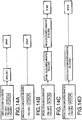
- Fig. 14A, 14B, 14C and 14D illustrate examples of commands of PDLs.
- each of PDL1-CM11, PDL2-CM12 and PDL3-CM 13 is a command for describing simple gradation using a simple color (hereafter, referred to as "simple color and simple gradation").
- These commands are converted into the command CM10 (AllPDL-CM10) of the "all PDL common intermediate language" by the programs 52, 62 and 72 as shown in Fig. 13 .
- the AllPDL-CM10 is converted into BMP data by the program 100 as shown in Fig. 13 .
- the program 100 is used as a common program common to PDL1-CM11, PDL2-CM12 and PDL3-CM13, for converting vector data into BMP data.
- Such a configuration makes it possible to decrease the data amount for programs.
- PDL1-CM91 is a command for describing complicated gradation using a simple color (hereafter, referred to as a "simple color and complicated gradation").
- the simple color and complicated gradation described by the PDL1-CM91 can not be described by another PDL, such as PDL2 or PDL 3.
- the "simple color and complicated gradation" which can be described only by a small number of types of PDLs (which is described only by PDL1 in this embodiment) is converted into BMP data without being converted into an intermediate language. In this case, only a program for directly converting PDL1-CM91 into BMP data is required.
- each of PDL1-CM71 and PDL2-CM72 is a command for describing simple gradation using a special color (hereafter, referred to as "special color and simple gradation").
- special color and simple gradation are converted into the command CM70 of the PDL1/2 common intermediate language (PDL1/2-CM70) by the programs 54 and 64 as shown in Fig. 13 .
- PDL1/2-CM70 is converted into the command CM70 of "all PDL common intermediate language" (AllPDL-CM70) by the program 92 as shown in Fig. 13 .
- the special color is converted into a simple color.
- the AllPDL-CM70 is converted into BMP data by the program 100 as shown in Fig. 13 . Since a common program for converting a special color into a simple color (i.e., the program 92) can be used for PDL1-CM71 and PDL2-CM72, the data amount for the programs can be decreased.
- each of PDL1-CM81 and PDL2-CM82 is a command describing complicated gradation using a special color (hereafter, referred to as "special color and complicated gradation").
- special color and complicated gradation are converted into the command CM80 of the PDL1/2 common intermediate language (PDL1/2-CM80) by the programs 54 and 64 as shown in Fig. 13 .
- the PDL1/2-CM80 is converted into BMP data without being converted into the intermediate language.
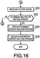
- Figs. 15 and 16 illustrate a flowchart of the PDL data conversion process.
- the PDL data conversion process is started when a print command and PDL data are inputted to the printer 10 via the network interface 12.
- step S110 the controller 14 reads a command contained at a top in the PDL data from the PC 140 (step S110).
- step S 110 is processed for the second time or later, a next command contained in the PDL is read.
- step S112 the controller 14 judges whether the command is to be subjected to the print operation.
- Step S 112 is repeated, until the controller 14 receives a command to be subjected to the print operation.
- the controller 14 makes a judgment of "NO" in step S112. In this case, control returns to step S110 to read a next command.
- step S114 the controller 14 judges whether the command read at step S110 is found in the All PDL command list 80 (see Fig. 13 ) (step S114). That is, the controller 114 judges whether the command read in step S110 is supported by the programs 52, 62 and 72 for converting the command into "all PDL common intermediate language". For example, if the command read in step S110 is the PDL1-CM11, the judgment result of step S114 is "YES". In this case, the controller 114 converts the command into the "all PDL common intermediate language" in accordance with the programs 52, 62 and 72 supporting the command read in step S110 (step S116).
- the controller 114 converts vector data in the command read in step S110 into vector data of the "all PDL common intermediate language".
- the command is converted into AllPDL-CM10 (see the program 52 in Fig. 13 and Fig. 14A ).
- step S116 is processed, control proceeds to step S30 of Fig. 16 .
- step S118 the controller 14 judges whether the command read in step S110 is contained in the PDL1/2 command list 82 (see Fig. 13 ) (step S118). That is, the controller 14 judges whether the command read in step S110 is supported by the programs 54 and 64 for converting the command into the PDL1/2 common intermediate language. For example, if the command read in step S110 is the PDL1-CM71, the judgement result of step S118 is "YES". In this case, the controller 114 converts the command into the PDL1/2 common intermediate language in accordance with the programs 54 and 64 which supports the command read in step S110 (step S120). In the case of the PDL1-CM71, the command is converted into PDL1/2 (see the program 54 in Fig. 2 and Fig. 14C ). After step S120 is processed, control proceeds to step S30 in Fig. 16 .
- step S122 the controller 14 judges whether a program for converting the command read in step S 110 into BMP data exists (step S122). For example, if the command read in step S110 is the PDL1-CM91, the judgment result of step S122 is "YES". In this case, the controller 114 converts the command into BMP data in accordance with the programs 56, 66 and 74 which support the command read in step S110. For example, as shown in Fig. 14B , the PDL1-CM91 is converted into BMP data without being converted into the intermediate language. After step S 124 is processed, control proceeds to step S30 in Fig. 16 .
- step S110 If the judgment result of step S122 is "NO", the command read in step S110 is not supported by any of the programs 50, 60 and 70. That is, the command read in step S110 is a command for which BMP data described in the command can not be generated. In this case, the controller 114 converts only a part of the command read in step S110 into BMP data in accordance with the alternative program 100 (step S126). For example, if the command read in step S110 contains coordinate data representing a contour and designation of filling the contour in complicated gradation, the controller 14 replaces the complicated gradation with a simple color, and generates BMP data reflecting accurately the coordinate data. After step S126 is processed, control proceeds to step S30 in Fig. 16 .
- step S30 of Fig. 16 the controller 14 writes the data generated in steps S116, S120, S124 and S126 (i.e., "all PDL common intermediate language", PDL1/2 common intermediate language, and BMP data) to a first buffer 20.
- the BMP data itself is written to the page memory 24 in a later process (i.e., in step S74 of Fig. 18 ).
- data representing a position of the BMP data on the page memory 24 is added to the BMP data.
- the BMP data may be written to the page memory 24 in step S30.
- step S32 judges whether the commands for a page of PDL data have been analyzed (step S32). If the commands tor a page of PDL data have not been processed (S32: NO), control returns to step S110 to read a next command. On the other hand, if all the commands for a page of PDL data have been processed (S32: YES), each of the commands of a page has been converted into another type of data, and the converted data has been stored in the first buffer 20. In this case, the controller 114 executes a first buffer memory content analyzing process (step S34) and a second buffer memory content analyzing process (S36) sequentially. The controller 14 executes the PDL data conversion process on the basis of a unit of a page of PDL data.
- the controller executes the PDL data conversion process for the second or subsequent page after processing the first page of the PDL data. It should be noted that the controller 114 may execute concurrently PDL data conversion processes for a plurality of pages of PDL data.
- Fig. 17 is a flowchart illustrating the first buffer memory content analyzing process executed in step S34 of Fig. 16 .
- the controller 14 reads data at a top of the first buffer (step S40).
- the controller 114 reads data at a next or subsequent position in the first buffer 20.
- the controller 114 judges whether the data read in step S40 is a command described in the PDL1/2 common intermediate language (step S42).
- the fact that the data read in step S40 is not a command described in the PDL1/2 common intermediate language (S42: NO) means the data read in step S40 is the "all PDL common intermediate language" or BMP data.
- the controller 114 writes the data read in step S40 itself into the second buffer 22 (step S54).
- step S44 judges whether the command read in step S40 (PDL1/2 common intermediate language) is found in the ALL PDL command list 80 (see Fig. 13 ) (step S44). That is, the controller 114 judges whether the command read in step S40 is supported by the program 92 for converting the command into "all PDL common intermediate language". Fir example, if the command read in step S40 is the PDL 1/2-CM70, the judgment result of step S44 becomes “YES". In this case, the controller 114 converts the command into the "all PDL common intermediate language" in accordance with the program 93 which supports the command read in step S40 (step S46).
- the command is converted into the AllPDL-CM70 (see the program 92 in Fig. 2 and Fig. 3C ). Through such processes, the special color is converted to a simple color.
- the controller 114 writes the data ("all PDL common intermediate language") generated in step S46 to the second buffer 22 (step S54).
- step S48 judges whether a program for generating the BMP data from the command read in step S40 exists (step S48). For example, if the command read in step S40 is the PDL1/2-CM80, the judgment result of step S48 is "YES". In this case, the controller 114 converts the command into BMP data in accordance with the program 94 which supports the command read in step S40 (step S50). In the case of the PDL1/2-CM80, the command is converted into BMP data (see the program 94 in Fig. 13 , and Fig. 14D ). Next, the controller 114 writes the BMP data generated in step S50 to the second buffer (step S54).
- step S48 If the judgment result of step S48 is "NO", the controller 114 converts a part of the command read in step S40 (the PDL1/2 common intermediate language) into BMP data (step S52). This step is the same as the step in S126. Next, the controller 114 writes the BMP data generated in step S52 to the second buffer 22 (step S54).
- step S54 the controller 114 judges whether all the commands in a page of PDL data stored in the first buffer 20 have been processed (step S56). If the judgment result of step S56 is "NO”, control returns to step S40 to process a next command. If the judgment result of step S56 is "YES”, the first buffer memory content analyzing process terminates. Then, the second buffer memory content analyzing process is executed (step S36 of Fig. 5 ).
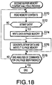
- Fig. 18 is a flowchart of the second buffer memory content analyzing process executed in step S36 in Fig. 16 .
- the controller 14 reads data at a top of the second buffer 22 (step S70).
- the controller 114 reads data at a next or subsequent position in the second buffer 22.
- the controller 114 judges whether the data obtained in step S70 is BMP data (step S72). If the data obtained in step S70 is BMP data (S72: YES), the controller 14 writes the BMP data itself into the page memory 24 (step S74).
- step S70 if the data obtained in step S70 is a command of the "all PDL common intermediate language", the judgment result of step S72 is "YES".
- the controller 114 converts the command into the BMP data in accordance with the program 100 which supports the "all PDL common intermediate language" obtained in step S70 (step S76). For example, each of AllPDL-CM 10 and AllPDL-CM70 is converted into the BMP data (see the program 100 of Fig. 13 and Figs. 14A and 14C ).
- the controller 114 writes the BMP data to the page memory 124.
- step S78 the controller 114 judges whether all the commands for a page stored in the second buffer 22 have been analyzed (step S78). If all the commands for a page have not been processed (S78: NO), control returns to step S70 to read a next command. If all the commands of a page have been processed (S78: YES), the second buffer memory content analyzing process terminates. As a result, the page memory 124 for one page can be completed. Then, the controller 114 instructs the print unit 128 to print an image corresponding to contents (i.e., BMP data) in the page memory 124. Then, the print unit 128 starts to carry a print medium and to print an image in the print medium.
- contents i.e., BMP data
- the vector data corresponding to "simple color simple gradation" in a unique format of each of the PDL1, PDL2 and PDL3 is converted into "all PDL common intermediate language". Then, the BMP data is generated from the vector data described in "all PDL common intermediate language". Therefore, regarding processing of the PDL1-PDL3, it is possible to provide a common program for generating the BMP data from the vector data described in "all PDL common intermediate language". Such a configuration makes it possible to decrease the data amount for programs.
- the vector data for "simple color and complicated gradation" is converted to BMP data without being converted to the intermediate language. Since the program for converting the vector data of the simple color and complicated gradation into "all PDL common intermediate language" is not required, it is possible to decrease the data amount for a required program.
- the alternative program 110 is used, it is possible to generate the BMP data from a part of the command even if BMP data described by the command can not be generated.
- a common program for generating another type of data from the command is used
- vector data of "simple color and simple gradation" described in a unique format of each of PDL1, PDL2 and PDL3 is converted into "all PDL common intermediate language”.
- BMP data is generated from vector data described in "all PDL common intermediate language”.
- a common program (program 100) for generating BMP data from "all PDL common intermediate language” can be used for PDL1, PDL 2 and PDL3.
- Such a configuration makes it possible to decrease the data amount for necessary programs.
- vector data for "simple color and complicated gradation” see Fig.
- the vector data is converted into BMP data without being converted into intermediate language. Since a program for converting vector data of "simple color and complicated gradation" into “all PDL common intermediate language" is not required, the data amount for necessary programs can be decreased.
- the alternative program 110 is used. Therefore, even if BMP data represented by a command can not be generated, BMP data can be generated from a part of the command.
- a common program is used for generating another type of data (e.g., "all PDL common intermediate language", "PDL1/2 common intermediate language” or BMP data) from such a common command.
- the command is converted into BMP data at step S124 or S126 in the PDL data conversion process shown in Fig. 15 .
- the command may be converted into BMP data at step S72 in the second buffer memory content analyzing process shown in Fig. 18 .
- the controller 14 may operate to write PDL1-CM91 to the first buffer 20 at step S124 in Fig. 15 , to write also PDL1-CM91 to the second buffer at step S54 in Fig. 17 , and then to convert PDL1-CM91 into BMP data at step S72 in Fig. 18 .
- Such a configuration makes it possible to decrease the necessary memory size because there is no necessity to store BMP data having a relatively large data size into each of the buffers 20 and 22.
- Such a configuration can be generally expressed as follows.
Landscapes
- Engineering & Computer Science (AREA)
- Theoretical Computer Science (AREA)
- Physics & Mathematics (AREA)
- Human Computer Interaction (AREA)
- General Engineering & Computer Science (AREA)
- General Physics & Mathematics (AREA)
- Mathematical Physics (AREA)
- Record Information Processing For Printing (AREA)
- Input From Keyboards Or The Like (AREA)
Claims (11)
- Seitenbeschreibungssprachverarbeitungsvorrichtung mit:einer Steuervorrichtung (114), undeinem Speicher (116), der computerlesbare Befehle speichert, die, wenn sie ausgeführt werden, die Seitenbeschreibungssprachverarbeitungsvorrichtung dazu veranlassen, als Folgendes zu wirken:eine Dateneingabeeinheit (112), die dazu konfiguriert ist, Eingabedaten aufzunehmen, die in einer Seitenbeschreibungssprache beschrieben sind, wobei die aufgenommenen Daten viele Befehle enthalten;wobei die Seitenbeschreibungssprachverarbeitungsvorrichtung dadurch gekennzeichnet ist, dass:die Steuervorrichtung (114) einen Programmspeicherbereich (118) aufweist, der dazu konfiguriert ist, Folgendes zu speichern:ein erstes Programm (52, 62, 72), das eine Funktion zum Umwandeln eines in einem vorbestimmten Format beschriebenen Befehls zu einem gemeinsamen Zwischenbefehl hat, der in einer Zwischensprache beschrieben ist und für viele Seitenbeschreibungssprachenarten gemeinsam ist; undein zweites Programm (54, 64), das eine Funktion zum Umwandeln eines in dem vorbestimmten Format beschriebenen Befehls zu einem Zwischenbefehl hat, der für zumindest zwei aber für weniger als alle der vielen Seitenbeschreibungsspracharten gemeinsam ist, undwobei der Speicher (116) des Weiteren computerlesbare Befehle speichert, die, wenn sie ausgeführt werden, die Seitenbeschreibungssprachverarbeitungsvorrichtung dazu veranlassen, als Folgendes zu dienen:eine erste Bestimmungseinheit (114), die dazu konfiguriert ist, zu bestimmen, ob ein von den Daten gelesener Befehl, die durch die Dateneingabeeinheit (112) aufgenommen sind, durch das erste Programm oder das zweite Programm umgewandelt werden kann, die in dem Programmspeicherbereich (118) gespeichert sind, und zwar für jede der vielen Befehle in den aufgenommenen Daten; undeine zweite Bestimmungseinheit, die dazu konfiguriert ist, zu bestimmen, welches von dem ersten oder dem zweiten Programm verwendet wird,eine Einheit zum Erzeugen eines gemeinsamen Zwischenbefehls, die dazu konfiguriert ist, den gemeinsamen Zwischenbefehl von dem Befehl zu erzeugen, der aus den von der Dateneingabeeinheit (112) aufgenommenen Daten gelesen wird, gemäß dem ersten Programm (52, 62, 72) oder dem zweiten Programm (54, 64), das durch die zweite Bestimmungseinheit bestimmt ist, als Reaktion auf die Bestimmung durch die erste Bestimmungseinheit (114), dass der Befehl, der von den Daten gelesen wird, die durch die Dateneingabeeinheit (112) aufgenommen werden, durch das erste Programm oder das zweite Programm gewandelt werden kann, die in dem Programmspeicherbereich (118) gespeichert sind;eine erste Bitmap-Datenerzeugungseinheit, die dazu konfiguriert ist, Bitmap-Daten von dem gemeinsamen Zwischenbefehl zu erzeugen, der durch die Einheit zum Erzeugen des gemeinsamen Zwischenbefehls erzeugt wird; undeine zweite Bitmap-Datenerzeugungseinheit, die dazu konfiguriert ist, aus dem Befehl, der von den durch die Dateneingabeeinheit (112) aufgenommenen Daten gelesen wird, direkt Bitmap-Daten zu erzeugen, ohne dass sie zu dem gemeinsame Zwischenbefehl umgewandelt werden, als Reaktion auf die Bestimmung durch die erste Bestimmungseinheit (114), dass der Befehl, der von den durch die Dateneingabeeinheit (112) aufgenommenen Daten gelesen wird, weder dem ersten Programm noch dem zweiten Programm entspricht, die in dem Programmspeicherbereich (118) gespeichert sind.
- Seitenbeschreibungssprachverarbeitungsvorrichtung gemäß Anspruch 1,
wobei der Speicher (116) des Weiteren computerlesbare Befehle speichert, die, wenn sie ausgeführt werden, die Seitenbeschreibungssprachverarbeitungsvorrichtung dazu veranlassen, als Folgendes zu wirken:eine erste Bitmap-Datenerzeugungsprogrammspeichereinheit (118), die dazu konfiguriert ist, ein Programm zu speichern, das eine Funktion zum Erzeugen von Bitmap-Daten aus den Daten hat, die in der Zwischensprache beschrieben sind;eine zweite Bitmap-Datenerzeugungsprogrammspeichereinheit (118), die dazu konfiguriert ist, ein Programm zu speichern, das eine Funktion zum Erzeugen eines Bitmap-Datenverzeichnisses von dem Befehl hat, der von den aufgenommenen Daten gelesen wird, für jede der vielen Seitenbeschreibungsspracharten, wobei:die erste Bitmap-Datenerzeugungseinheit die Bitmap-Daten von dem gemeinsamen Zwischenbefehl gemäß dem Programm erzeugt, das in der ersten Bitmap-Datenerzeugungsprogrammspeichereinheit gespeichert ist; unddie zweite Bitmap-Datenerzeugungseinheit das Bitmap-Datenverzeichnis von dem Befehl erzeugt, der von den aufgenommenen Daten gelesen wird, die in dem Beschreibungsformat beschrieben sind, gemäß dem Programm, das in der zweiten Bitmap-Datenerzeugungsprogrammspeichereinheit gespeichert ist. - Seitenbeschreibungssprachverarbeitungsvorrichtung gemäß Anspruch 2,
wobei der Speicher (116) des Weiteren computerlesbare Befehle speichert, die, wenn sie ausgeführt werden, die Seitenbeschreibungssprachverarbeitungsvorrichtung dazu veranlassen, als Folgendes zu wirken;
eine dritte Bestimmungseinheit (114), die dazu konfiguriert ist, zu bestimmen, ob der von den aufgenommenen Daten gelesene Befehl dem Programm entspricht, das in der zweiten Bitmap-Datenerzeugungsprogrammspeichereinheit gespeichert ist, wobei:die zweite Bitmap-Datenerzeugungseinheit dazu konfiguriert ist:die Bitmap-Daten von den gesamten Daten zu erzeugen, die durch die Dateneingabeeinheit (112) aufgenommen werden, die in dem Beschreibungsformat gemäß einem dritten Programm beschrieben sind, das in der zweiten Bitmap-Datenerzeugungsprogrammspeichereinheit gespeichert ist, als Reaktion auf eine Tatsache, dass die erste Bestimmungseinheit bestimmt, dass der von den aufgenommenen Daten gelesene Befehl weder dem ersten Programm noch dem zweiten Programm entspricht, die in dem Programmspeicherbereich (118) gespeichert sind, und dass die dritte Bestimmungseinheit bestimmt, dass der von den aufgenommenen Daten gelesene Befehl dem Programm entspricht, das in der zweiten Bitmap-Datenerzeugungsprogrammspeichereinheit (124) gespeichert ist; unddie Bitmap-Daten von einem Teil der Daten zu erzeugen, die durch die Dateneingabeeinheit (112) aufgenommen werden, als Reaktion auf eine Tatsache, dass die erste Bestimmungseinheit bestimmt, dass der von den aufgenommenen Daten gelesene Befehl weder dem ersten Programm noch dem zweiten Programm entspricht, die in dem Programmspeicherbereich (118) gespeichert sind, und dass die dritte Bestimmungseinheit bestimmt, dass der von den aufgenommenen Daten gelesene Befehl nicht dem Programm entspricht, das in der zweiten Bitmap-Datenerzeugungsprogrammspeichereinheit (124) gespeichert ist. - Seitenbeschreibungssprachverarbeitungsvorrichtung gemäß Anspruch 2 oder 3,
wobei die zweite Bitmap-Datenerzeugungsprogrammspeichereinheit ein gemeinsames Programm speichert, das eine Funktion zum Erzeugen von Bitmap-Daten von Daten hat, die in einem gemeinsamen Format beschrieben sind, das für zumindest zwei Seitenbeschreibungsspracharten gemeinsam ist. - Seitenbeschreibungssprachverarbeitungsvorrichtung gemäß einem der Ansprüche 1 bis 3,
wobei das zweite Programm eine Funktion zum Erzeugen von Daten hat, die in einer zweiten Zwischensprache beschrieben sind, die sich von der Zwischensprache unterscheidet, aus dem Befehl, der aus den aufgenommenen Daten gelesen wird; und
wobei der Programmspeicherbereich (118) ein drittes Programm speichert, das eine Funktion zum Erzeugen des gemeinsamen Zwischenbefehls aus den Daten hat, die in der zweiten Zwischensprache beschrieben sind; und
wobei die Einheit zum Erzeugen eines gemeinsamen Zwischenbefehls zu Folgendem betrieben wird:Erzeugen der Daten, die in der zweiten Zwischensprache beschrieben ist, aus dem Befehl, der von den aufgenommenen Daten gelesen wird, gemäß dem zweiten Programm als Reaktion auf eine Bestimmung, dass ein Befehl, der von den aufgenommenen Daten gelesen wird, dem zweiten Programm entspricht; undErzeugen des gemeinsamen Zwischenbefehls von den Daten, die in der zweiten Zwischensprache beschrieben sind, gemäß dem dritten Programm. - Seitenbeschreibungssprachverarbeitungsvorrichtung gemäß Anspruch 5, wobei:der Programmspeicherbereich (118) ein viertes Programm speichert, das eine Funktion zum Erzeugen von Daten hat, die in der Zwischensprache beschrieben ist, aus den Daten, die in einem zweiten vorbestimmten Format der Seitenbeschreibungssprache beschrieben sind, zumindest für die zwei Seitenbeschreibungsspracharten; unddie Einheit zum Erzeugen des gemeinsamen Zwischenbefehls die Daten erzeugt, die in der Zwischensprache beschrieben sind, aus dem Befehl, der aus den aufgenommenen Daten gelesen wird, gemäß dem vierten Programm als Reaktion auf eine Bestimmung, dass der Befehl, der von den aufgenommenen Daten gelesen wird, dem vierten Programm entspricht.
- Verfahren, das bei einer Seitenbeschreibungssprachverarbeitungsvorrichtung zu implementieren ist, wobei das Verfahren die folgenden Schritte aufweist:Aufnehmen von Eingabedaten, die in einer Seitenbeschreibungssprache beschrieben sind, wobei die aufgenommenen Daten viele Befehle enthalten;Speichern eines ersten Programms (52, 62, 72), das eine Funktion zum Umwandeln eines in einem vorbestimmten Format beschriebenen Befehls zu einem gemeinsamen Zwischenbefehl hat, der in einer Zwischensprache beschrieben ist und für viele Seitenbeschreibungsspracharten gemeinsam ist; undSpeichern eines zweiten Programms (54, 64), das eine Funktion zum Umwandeln eines Befehls zu einem Zwischenbefehl hat, der für zumindest zwei aber für weniger als alle der vielen Seitenbeschreibungsspracharten gemeinsam ist;einen ersten Bestimmungsschritt zum Bestimmen, ob ein Befehl, der von den aufgenommenen Daten gelesen wird, durch das gespeicherte erste Programm oder das gespeicherte zweite Programm für jeden der vielen Befehle in den aufgenommenen Daten (S114) umgewandelt werden kann; undeinen zweiten Bestimmungsschritt zum Bestimmen, welches von dem ersten und dem zweiten Programm zu verwenden ist;Erzeugen des gemeinsamen Zwischenbefehls aus dem Befehl, der von den aufgenommenen Daten gelesen wird, gemäß dem ersten Programm (52, 62, 72) oder dem zweiten Programm (54, 64), das durch den zweiten Bestimmungsschritt bestimmt ist, als Reaktion auf den ersten Bestimmungsschritt, der bestimmt, dass der aus den aufgenommenen Daten gelesene Befehl durch das gespeicherte erste Programm oder das gespeicherte zweite Programm umgewandelt werden kann (S116);Erzeugen von ersten Bitmap-Daten aus dem erzeugten, gemeinsamen Zwischenbefehl (S124); undErzeugen von zweiten Bitmap-Daten direkt aus dem Befehl, der aus den aufgenommenen Daten gelesen wird, ohne dass der Befehl in den gemeinsamen Zwischenbefehl umgewandelt wird, als Reaktion auf den ersten Bestimmungsschritt, der bestimmt, dass der aus den aufgenommenen Daten gelesene Befehl weder dem gespeicherten ersten Programm noch dem gespeicherten zweiten Programm entspricht (S126).
- Verfahren gemäß Anspruch 7,
des Weiteren mit den folgenden Schritten:Speichern eines ersten Bitmap-Datenerzeugungsprogramms, das eine Funktion zum Erzeugen von Bitmap-Daten aus den Daten hat, die in der Zwischensprache beschrieben sind;Speichern eines zweiten Bitmap-Datenerzeugungsprogramms, das eine Funktion zum Erzeugen eines Bitmap-Datenverzeichnisses aus dem Befehl hat, der aus den aufgenommenen Daten gelesen wird, für jede der vielen Seitenbeschreibungsspracharten,Erzeugen der Bitmap-Daten aus dem gemeinsamen Zwischenbefehl gemäß dem ersten Bitmap-Datenerzeugungsprogramm; undErzeugen des Bitmap-Datenverzeichnisses aus dem Befehl, der aus den aufgenommenen Daten gelesen wird, gemäß dem zweiten Bitmap-Datenerzeugungsprogramm. - Verfahren gemäß Anspruch 8,
des Weiteren mit den folgenden Schritten:einem dritten Bestimmungsschritt zum Bestimmen, ob der aus den aufgenommenen Daten gelesene Befehl dem zweiten Bitmap-Datenerzeugungsprogramm entspricht,Erzeugen der Bitmap-Daten aus den gesamten aufgenommenen Daten, die in dem Beschreibungsformat beschrieben sind, gemäß einem dritten Programm als Reaktion auf eine Tatsache, dass der erste Bestimmungsschritt bestimmt, dass der aus den aufgenommenen Daten gelesene Befehl weder dem gespeicherten ersten Programm noch dem gespeicherten zweiten Programm entspricht, und dass der dritte Bestimmungsschritt bestimmt, dass der aus den aufgenommenen Daten gelesene Befehl dem zweiten Bitmap-Datenerzeugungsprogramm entspricht; undErzeugen der Bitmap-Daten aus einem Teil der aufgenommenen Daten als Reaktion auf den ersten Bestimmungsschritt, der bestimmt, dass der aus den aufgenommenen Daten gelesene Befehl weder dem gespeicherten ersten Programm noch dem gespeicherten zweiten Programm entspricht, und auf den dritten Bestimmungsschritt, der bestimmt, dass der aus den aufgenommenen Daten gelesene Befehl nicht dem zweiten Bitmap-Datenerzeugungsprogramm entspricht. - Verfahren gemäß Anspruch 8 oder 9,
mit dem Schritt zum Speichern eines gemeinsamen Programms, das eine Funktion zum Erzeugen von Bitmap-Daten aus Daten hat, die in einem gemeinsamen Format beschrieben sind, das für zumindest zwei Seitenbeschreibungssprachen gemeinsam ist. - Computerlesbares Medium mit computerlesbaren Befehlen, die darin gespeichert sind, die, wenn sie durch einen Computer ausgeführt werden, der als eine Seitenbeschreibungssprachverarbeitungsvorrichtung dient, dazu konfiguriert sind, die Schritte des Verfahrens gemäß einem der Ansprüche 7-10 auszuführen.
Applications Claiming Priority (2)
| Application Number | Priority Date | Filing Date | Title |
|---|---|---|---|
| JP2008037130A JP2009199130A (ja) | 2008-02-19 | 2008-02-19 | ページ記述言語処理装置、ページ記述言語処理プログラム |
| JP2008089613A JP4613975B2 (ja) | 2008-03-31 | 2008-03-31 | ページ記述言語処理装置 |
Publications (3)
| Publication Number | Publication Date |
|---|---|
| EP2093659A2 EP2093659A2 (de) | 2009-08-26 |
| EP2093659A3 EP2093659A3 (de) | 2010-12-29 |
| EP2093659B1 true EP2093659B1 (de) | 2017-07-19 |
Family
ID=40651749
Family Applications (1)
| Application Number | Title | Priority Date | Filing Date |
|---|---|---|---|
| EP09250416.6A Active EP2093659B1 (de) | 2008-02-19 | 2009-02-18 | Vorrichtung, Verfahren und computerlesbares Medium zur Seitenbeschreibungssprachverarbeitung |
Country Status (2)
| Country | Link |
|---|---|
| US (1) | US8566715B2 (de) |
| EP (1) | EP2093659B1 (de) |
Families Citing this family (6)
| Publication number | Priority date | Publication date | Assignee | Title |
|---|---|---|---|---|
| US10642896B2 (en) * | 2016-02-05 | 2020-05-05 | Sas Institute Inc. | Handling of data sets during execution of task routines of multiple languages |
| US10650046B2 (en) | 2016-02-05 | 2020-05-12 | Sas Institute Inc. | Many task computing with distributed file system |
| US10795935B2 (en) | 2016-02-05 | 2020-10-06 | Sas Institute Inc. | Automated generation of job flow definitions |
| USD898059S1 (en) | 2017-02-06 | 2020-10-06 | Sas Institute Inc. | Display screen or portion thereof with graphical user interface |
| USD898060S1 (en) | 2017-06-05 | 2020-10-06 | Sas Institute Inc. | Display screen or portion thereof with graphical user interface |
| CN112257006B (zh) * | 2020-11-11 | 2024-07-19 | 汉海信息技术(上海)有限公司 | 页面信息的配置方法、装置、设备及计算机可读存储介质 |
Family Cites Families (17)
| Publication number | Priority date | Publication date | Assignee | Title |
|---|---|---|---|---|
| WO1991015831A1 (fr) * | 1990-04-05 | 1991-10-17 | Seiko Epson Corporation | Interpreteur de langage de description de page |
| US5303336A (en) * | 1990-05-14 | 1994-04-12 | Hitachi, Ltd. | Printing system including print server |
| JP3245151B2 (ja) | 1990-09-19 | 2002-01-07 | 富士ゼロックス株式会社 | ページ記述言語処理装置およびページ記述言語処理印刷装置 |
| JP2783344B2 (ja) | 1992-05-18 | 1998-08-06 | キヤノン株式会社 | プリンタ制御装置及びその制御方法 |
| JP2812412B2 (ja) | 1992-05-18 | 1998-10-22 | キヤノン株式会社 | プリンタ制御装置及び方法 |
| EP0571145B1 (de) * | 1992-05-18 | 1999-10-13 | Canon Kabushiki Kaisha | Vorrichtung zur Übersetzung von Druckersteurungssprachen |
| JP3094712B2 (ja) | 1992-12-29 | 2000-10-03 | 富士ゼロックス株式会社 | ページ記述言語処理装置 |
| JPH0789150A (ja) | 1993-09-22 | 1995-04-04 | Fuji Xerox Co Ltd | プリンタ制御装置 |
| US5729665A (en) * | 1995-01-18 | 1998-03-17 | Varis Corporation | Method of utilizing variable data fields with a page description language |
| US6665081B1 (en) * | 1996-07-19 | 2003-12-16 | Seiko Epson Corporation | Print system printer driver and printer |
| JP3585206B2 (ja) | 1997-07-02 | 2004-11-04 | キヤノン株式会社 | 出力装置および出力方法 |
| JP2001222396A (ja) * | 2000-02-10 | 2001-08-17 | Matsushita Graphic Communication Systems Inc | プリンタコントローラ及びプリンタ言語切替方法 |
| JP3494966B2 (ja) | 2000-09-04 | 2004-02-09 | 株式会社東芝 | 無線装置 |
| JP2004192038A (ja) | 2002-12-06 | 2004-07-08 | Sharp Corp | 情報処理装置、情報処理システム、情報処理プログラム、および該プログラムを記録した記録媒体 |
| JP2005161756A (ja) | 2003-12-04 | 2005-06-23 | Canon Inc | 画像処理装置及び画像処理装置の制御方法 |
| JP4534713B2 (ja) * | 2004-10-22 | 2010-09-01 | ブラザー工業株式会社 | 印刷装置及びプログラム |
| JP4416782B2 (ja) * | 2006-12-15 | 2010-02-17 | キヤノン株式会社 | 画像処理装置、決定装置、変更装置、および画像処理方法 |
-
2009
- 2009-02-18 EP EP09250416.6A patent/EP2093659B1/de active Active
- 2009-02-19 US US12/388,812 patent/US8566715B2/en active Active
Non-Patent Citations (1)
| Title |
|---|
| None * |
Also Published As
| Publication number | Publication date |
|---|---|
| EP2093659A2 (de) | 2009-08-26 |
| US8566715B2 (en) | 2013-10-22 |
| EP2093659A3 (de) | 2010-12-29 |
| US20090210785A1 (en) | 2009-08-20 |
Similar Documents
| Publication | Publication Date | Title |
|---|---|---|
| EP2093659B1 (de) | Vorrichtung, Verfahren und computerlesbares Medium zur Seitenbeschreibungssprachverarbeitung | |
| JP2006285870A (ja) | 印刷制御装置、印刷制御方法、及びプログラム | |
| JPH10285421A (ja) | プリンタ色処理モード自動制御装置、その方法、その受信装置、システム及びその記憶媒体 | |
| JP2005208894A (ja) | 周辺装置制御方法、制御プログラム及びその装置 | |
| EP0684546B1 (de) | Drucker, Druckersystem und Verfahren, um die Zeichenbetriebsmittel des Druckerssystems zu erfahren | |
| JP2010026895A (ja) | 情報処理装置、画像形成装置、およびプログラム | |
| US7612899B2 (en) | Print data processing system | |
| JPH1040031A (ja) | プリントシステム、プリンタドライバ及びプリンタ | |
| JP4522314B2 (ja) | 情報処理装置及びそのカラー/モノクロ判定方法、並びにプログラム | |
| JP4784361B2 (ja) | 印刷システム、情報処理装置、およびプログラム | |
| JP4072286B2 (ja) | 出力制御装置、制御方法、記憶媒体 | |
| JP2010208170A (ja) | 画像形成装置、画像形成方法、および画像形成プログラム | |
| JP5679644B2 (ja) | 情報処理装置、その制御方法、及びプログラム | |
| US8374902B2 (en) | Information processing apparatus and information processing method | |
| JP2009132040A (ja) | 印刷装置、および印刷装置の印刷データ処理方法 | |
| JP3230516B2 (ja) | プリンタ、記録媒体およびプリンタのメモリ管理方法 | |
| US7310166B2 (en) | Information processing apparatus and method, and print control program | |
| JP2023015686A (ja) | 印刷装置、印刷システムおよびプログラム | |
| US10152657B2 (en) | Image processing apparatus and image processing method of color image | |
| JP3129679B2 (ja) | プリンタ | |
| US20250383827A1 (en) | Non-transitory computer-readable storage medium storing supporting program | |
| US20060044588A1 (en) | Image forming apparatus and printing system | |
| JP2001228996A (ja) | 画像形成システム | |
| JP2009086722A (ja) | 情報処理装置、情報処理方法、プログラム、及び記憶媒体 | |
| US20080174828A1 (en) | Image processing system, image processing method, computer readable medium, and computer data signal |
Legal Events
| Date | Code | Title | Description |
|---|---|---|---|
| PUAI | Public reference made under article 153(3) epc to a published international application that has entered the european phase |
Free format text: ORIGINAL CODE: 0009012 |
|
| AK | Designated contracting states |
Kind code of ref document: A2 Designated state(s): AT BE BG CH CY CZ DE DK EE ES FI FR GB GR HR HU IE IS IT LI LT LU LV MC MK MT NL NO PL PT RO SE SI SK TR |
|
| AX | Request for extension of the european patent |
Extension state: AL BA RS |
|
| PUAL | Search report despatched |
Free format text: ORIGINAL CODE: 0009013 |
|
| AK | Designated contracting states |
Kind code of ref document: A3 Designated state(s): AT BE BG CH CY CZ DE DK EE ES FI FR GB GR HR HU IE IS IT LI LT LU LV MC MK MT NL NO PL PT RO SE SI SK TR |
|
| AX | Request for extension of the european patent |
Extension state: AL BA RS |
|
| 17P | Request for examination filed |
Effective date: 20110504 |
|
| AKX | Designation fees paid |
Designated state(s): DE FR GB |
|
| 17Q | First examination report despatched |
Effective date: 20121126 |
|
| GRAP | Despatch of communication of intention to grant a patent |
Free format text: ORIGINAL CODE: EPIDOSNIGR1 |
|
| STAA | Information on the status of an ep patent application or granted ep patent |
Free format text: STATUS: GRANT OF PATENT IS INTENDED |
|
| INTG | Intention to grant announced |
Effective date: 20170222 |
|
| GRAS | Grant fee paid |
Free format text: ORIGINAL CODE: EPIDOSNIGR3 |
|
| GRAA | (expected) grant |
Free format text: ORIGINAL CODE: 0009210 |
|
| STAA | Information on the status of an ep patent application or granted ep patent |
Free format text: STATUS: THE PATENT HAS BEEN GRANTED |
|
| AK | Designated contracting states |
Kind code of ref document: B1 Designated state(s): DE FR GB |
|
| REG | Reference to a national code |
Ref country code: GB Ref legal event code: FG4D |
|
| REG | Reference to a national code |
Ref country code: DE Ref legal event code: R096 Ref document number: 602009047187 Country of ref document: DE |
|
| REG | Reference to a national code |
Ref country code: FR Ref legal event code: PLFP Year of fee payment: 10 |
|
| REG | Reference to a national code |
Ref country code: DE Ref legal event code: R097 Ref document number: 602009047187 Country of ref document: DE |
|
| PLBE | No opposition filed within time limit |
Free format text: ORIGINAL CODE: 0009261 |
|
| STAA | Information on the status of an ep patent application or granted ep patent |
Free format text: STATUS: NO OPPOSITION FILED WITHIN TIME LIMIT |
|
| 26N | No opposition filed |
Effective date: 20180420 |
|
| P01 | Opt-out of the competence of the unified patent court (upc) registered |
Effective date: 20230529 |
|
| PGFP | Annual fee paid to national office [announced via postgrant information from national office to epo] |
Ref country code: GB Payment date: 20260113 Year of fee payment: 18 |
|
| PGFP | Annual fee paid to national office [announced via postgrant information from national office to epo] |
Ref country code: DE Payment date: 20260115 Year of fee payment: 18 |
|
| PGFP | Annual fee paid to national office [announced via postgrant information from national office to epo] |
Ref country code: FR Payment date: 20260109 Year of fee payment: 18 |