EP2093732A1 - Dispositif et procédé de détection de fumée à l'aide de l'évaluation collective de deux signaux à rétrodiffusion optiques - Google Patents
Dispositif et procédé de détection de fumée à l'aide de l'évaluation collective de deux signaux à rétrodiffusion optiques Download PDFInfo
- Publication number
- EP2093732A1 EP2093732A1 EP08101743A EP08101743A EP2093732A1 EP 2093732 A1 EP2093732 A1 EP 2093732A1 EP 08101743 A EP08101743 A EP 08101743A EP 08101743 A EP08101743 A EP 08101743A EP 2093732 A1 EP2093732 A1 EP 2093732A1
- Authority
- EP
- European Patent Office
- Prior art keywords
- light
- receiver
- smoke
- emitter
- light receiver
- Prior art date
- Legal status (The legal status is an assumption and is not a legal conclusion. Google has not performed a legal analysis and makes no representation as to the accuracy of the status listed.)
- Withdrawn
Links
Images
Classifications
-
- G—PHYSICS
- G08—SIGNALLING
- G08B—SIGNALLING SYSTEMS, e.g. PERSONAL CALLING SYSTEMS; ORDER TELEGRAPHS; ALARM SYSTEMS
- G08B29/00—Checking or monitoring of signalling or alarm systems; Prevention or correction of operating errors, e.g. preventing unauthorised operation
- G08B29/18—Prevention or correction of operating errors
- G08B29/20—Calibration, including self-calibrating arrangements
- G08B29/22—Provisions facilitating manual calibration, e.g. input or output provisions for testing; Holding of intermittent values to permit measurement
-
- G—PHYSICS
- G08—SIGNALLING
- G08B—SIGNALLING SYSTEMS, e.g. PERSONAL CALLING SYSTEMS; ORDER TELEGRAPHS; ALARM SYSTEMS
- G08B17/00—Fire alarms; Alarms responsive to explosion
- G08B17/10—Actuation by presence of smoke or gases, e.g. automatic alarm devices for analysing flowing fluid materials by the use of optical means
- G08B17/103—Actuation by presence of smoke or gases, e.g. automatic alarm devices for analysing flowing fluid materials by the use of optical means using a light emitting and receiving device
-
- G—PHYSICS
- G01—MEASURING; TESTING
- G01N—INVESTIGATING OR ANALYSING MATERIALS BY DETERMINING THEIR CHEMICAL OR PHYSICAL PROPERTIES
- G01N21/00—Investigating or analysing materials by the use of optical means, i.e. using sub-millimetre waves, infrared, visible or ultraviolet light
- G01N21/17—Systems in which incident light is modified in accordance with the properties of the material investigated
- G01N21/47—Scattering, i.e. diffuse reflection
- G01N2021/4704—Angular selective
- G01N2021/4709—Backscatter
-
- G—PHYSICS
- G08—SIGNALLING
- G08B—SIGNALLING SYSTEMS, e.g. PERSONAL CALLING SYSTEMS; ORDER TELEGRAPHS; ALARM SYSTEMS
- G08B17/00—Fire alarms; Alarms responsive to explosion
- G08B17/10—Actuation by presence of smoke or gases, e.g. automatic alarm devices for analysing flowing fluid materials by the use of optical means
- G08B17/11—Actuation by presence of smoke or gases, e.g. automatic alarm devices for analysing flowing fluid materials by the use of optical means using an ionisation chamber for detecting smoke or gas
- G08B17/113—Constructional details
Definitions
- the present invention relates to the technical field of danger detection technology.
- the present invention relates to a device for detecting smoke based on the principle of optical scattered light measurements.
- the present invention further relates to a method based on the principle of optical scattered light measurements for detecting smoke.
- Optical or photoelectric smoke detectors usually work according to the scattered light method. It is exploited that clear air reflects virtually no light. However, if smoke particles are in the air, an illuminating light emitted by an infrared light-emitting diode is at least partially scattered on the smoke particles. Part of this scattered light then falls on a photosensitive sensor, which is not directly illuminated by the light beam. Without smoke particles in the air, the illumination light can not reach the photosensitive sensor.
- a smoke detector which comprises a housing and disposed within the housing has a light emitter and a light receiver. A defined by the spatial arrangement of light emitter and light receiver smoke detection area is located outside the smoke detector.
- the light transmitter is assigned a control receiver, which is set up to detect the radiation emitted by the light emitter. Furthermore, a control transmitter assigned to the light receiver is provided that the sensitivity of the light receiver can be checked.
- a fire detector is known, which is based on the known scattered radiation principle.
- the fire detector has a plurality of radiation transmitters and a plurality of radiation receivers whose radiation paths define a plurality of spaced-apart scattering volumes or detection spaces.
- the detection spaces are spatially spaced such that small objects such as insects can not move through multiple detection spaces simultaneously. In this way, a distinction can be made reliably between a light scattered on a small measurement object and a fire, in which smoke a distinction is made between smoke distributed over all detection spaces.
- a fire detector which can be mounted in a flush on a ceiling of a room to be monitored.
- the fire detector has a radiation transmitter and a radiation receiver, which are mounted side by side on a detector insert.
- a film can be inserted, the color of which can be adapted to the ceiling color of the space to be monitored.
- the fire detector can be adapted to the interior design of the room to be monitored, so that the fire detector is not or hardly perceived by people in the room.
- the fire detector has a laser light source, which is set up to emit short laser pulses in a surveillance area.
- the fire detector further comprises a light detector, which is arranged next to the laser light source and which is arranged, located in the monitoring area smoke or other Objects to detect 180 ° backscattered laser light. Based on the time difference between emitted and received laser pulses, the position of a backscatter object can be determined within the surveillance area. By a suitable comparison with time differences obtained by reference measurements, the type of detected smoke can also be detected. In particular, a distinction can be made between black and white smoke.
- the object of the present invention is to improve the detection of smoke, especially with regard to the probability of false alarms, with a low outlay on equipment.
- an apparatus for detecting smoke comprises (a) a base element with a planar mounting surface, (b) a first light transmitter which is attached to the mounting surface and which is adapted to emit a first illumination light, and (c) a first light receiver which is adjacent to the first Light transmitter is mounted on the mounting surface and which is adapted to receive a first measuring light, which results from a backscattering of the first illumination light at a measurement object located in a first detection space.
- the described device further comprises (d) a second light emitter mounted on the mounting surface and adapted to emit a second illumination light, (e) a second photoreceptor mounted adjacent the second light emitter on the mounting surface and which is for receiving set up a second measuring light and (f) a data processing device which is coupled to the first light receiver and the second light receiver and which for jointly evaluating a first output signal of the first light receiver and a second output signal of a second light receiver is set up.
- the described device for detecting smoke which device is also referred to below as smoke detector, is based on the finding that the smoke detector can be realized by a planar arrangement of all optoelectronic components on a common mounting surface in a particularly flat design. In this case, the first detection space and the second detection space is outside the actual smoke detector. Thus, the described smoke detector is an open smoke detector.
- detection space is understood to mean a layer which directly adjoins the smoke detector. Smoke that is within the detection space will then result in a significant and measurable optical backscatter signal. Smoke, which is outside the Detection space is located and which is therefore further spaced from the smoke detector, will not contribute significantly to the received backscatter signal.
- the term "field of view of the smoke detector” is understood to mean the area which is basically detected by the smoke detector and which lies outside the detection area. As explained above, smoke that is in the field of view of the smoke detector can not significantly contribute to the optical backscatter signal. However, this does not apply to objects in dispute such as insects or furniture. Even if they are only in the field of vision of the smoke detector, they can lead to a noticeable optical backscatter signal.
- the described smoke detector Due to the flat design, it is possible to easily integrate the smoke detector described in the walls and in particular in the ceilings of monitored areas. Even in the case of surface mounting, the described smoke detector can be easily attached to walls and / or ceilings. The smoke detector only takes up a small amount of space. In addition, the smoke detector described can be installed discreetly, so that it is not perceived by people who are in the monitored by the smoke detector room, or at least not disturbing the interior design.
- the measured object is in particular smoke, which has individual smoke particles, which are detected by the described based on the scattered light principle smoke detector.
- the measurement object may also be another object such as an insect or an object accidentally introduced into the detection space, which also generate a backscatter signal.
- the optical backscatter signals from objective objects in the detection space, such as insects in particular are in comparison to the smoke-induced optical backscatter signals considerably stronger.
- by properly evaluating the output signals of the first and second light detectors by the data processing device such events can be reliably distinguished from the actual presence of smoke.
- the smoke detector described can be made particularly cost-effective and is suitable as a low-cost mass product for monitoring private rooms.
- the measurement of the scattered light takes place in the described smoke detector in scrubstreugeometrie of approximately 180 °.
- the deviation of the scattering angle from an exact backscatter, and thus exactly 180 ° results from (a) the spacing between the first and second light emitters and the first and second photodetectors and (b) the distance of the backscatter location from the respective ones Light emitter or light receiver.
- a clear deviation of the scattering angle of 180 ° can result due to a small layer thickness of the detection space.
- the smoke detector described differs in particular by the used backscatter geometry of conventional smoke detectors, which have either a forward scatterer a scattering angle of about 60 ° or as a back scatterer a scattering angle of about 120 ° between the illumination light and scattered light.
- the optoelectronic or photoelectronic components of the smoke detector can advantageously be semiconductor diodes applied in Surface Mount Technology.
- the base member may be a printed circuit board or at least have a printed circuit board on which the Halbleitersende- and Semiconductor receiving diodes are mounted in a known manner and electrically contacted.
- the term light basically comprises electromagnetic waves in any spectral range. These include, for example, the ultraviolet, the visible and the infrared spectral range. Even longer wavy radiation such as microwaves represent light in the context of the present application.
- the term light electromagnetic radiation in the near infrared spectral range meant in which light emitting diodes used as light emitters have a particularly high light intensity.
- the described smoke detector can be operated not only with nearly monochromatic light radiation but also with light radiation which comprises two or more discrete wavelengths and / or a wavelength continuum.
- the first light transmitter and the first light receiver are realized by a first reflection light barrier and / or the second light transmitter and the second light receiver by a second reflection light barrier.
- a relative adjustment between a light emitter and the corresponding light receiver for adapting the emission direction of the light emitter to the receiving direction of the light receiver is not required due to the fixed relative arrangement of these optoelectronic components within a common component or at least within a common housing.
- the smoke detector can therefore be constructed in an advantageous manner with a low installation cost.
- the direction of the first illumination light is related to a normal of the mounting surface in the direction of the first light receiver is inclined and / or the direction of the second illumination light is inclined with respect to the normal of the mounting surface in the direction of the second light receiver.
- the term direction in this context means the average emission direction of the first and / or the second light emitter.
- the light emitters can not only be lasers, such as a vertical cavity surface emitting laser (VCSEL), which emit a nearly parallel beam of light.
- VCSEL vertical cavity surface emitting laser
- the light emitters may also have a radiation characteristic with diverging light beams, which have a certain angular distribution around the corresponding mean emission direction inclined towards the respective light receiver.
- the direction of the first illumination light and the direction of the second illumination light are parallel to each other.
- the direction of the illumination light in each case refers to the central emission direction.
- the first light emitter and the second light emitter as well as the first light receiver and the second light receiver each represent an outer boundary of the device for detecting smoke.
- covers or housing parts can be designed such that there is no further optionally optically transparent cover between the photoelectric components and the respective detection space, through which the photoelectric components are protected from contamination.
- covers or dirt shields are in many applications, especially in the home but also not required.
- the first detection space and / or the second detection space may also be located outside the smoke detector.
- the device for detecting smoke represents an open smoke detector, which does not have its own optical chamber.
- the smoke detector additionally has a subtraction unit, which is coupled on the input side to the first light receiver and the second light receiver and which on the output side to the data processing device.
- the subtraction unit can be realized for example by means of suitable hardware components, which determine a difference signal between the first output signal and the second output signal based on analog output signals of the two light receivers. This difference signal can then be evaluated in a suitable manner by a processor of the data processing device.
- the subtraction unit can likewise be integrated in the data processing device and implemented there either by means of hardware, by means of software or by means of my combination of hardware and software.
- the influence of extraneous light sources can be eliminated, which light from outside into the two light receivers irradiate and thus provide for each individual light receiver for a falsely increased received signal.
- the first light receiver is set up to detect a time profile of the first measuring light.
- the backscatter light intensity detected by the first light receiver By detecting the backscatter light intensity detected by the first light receiver as a function of time, information about a scattering object penetrating into the first detection space can be obtained in a simple manner. If smoke is involved in the penetrating scattering object, the time change of the backscatter intensity will be comparatively slow, since smoke usually penetrates continuously into the detection space. In contrast to this, in the case of an objective measurement object such as, for example, an insect or an object accidentally introduced by a person into the field of vision of the described smoke detector, an essentially abrupt change in the backscatter intensity will occur. Thus, based on the magnitude of the temporal change of the backscatter intensity detected by the first light receiver, reliable information about the type of scattering object can be obtained.
- the first light transmitter is configured to emit a pulsed first illumination light.
- pulsed illumination light with very short light pulses with a time length of preferably less than 1 ns in conjunction with a light receiver having a temporal resolution, which is also in the nanosecond range has the advantage that information about the spatial distribution of the light scatterers won can be.
- a first optical reflection signal which originates from the bottom of a arranged on the ceiling of a room smoke detector
- a second reflection signal which results from a scattering of smoke
- smoke only provides a significant reflection signal when it is within a located near the smoke detector detection space.
- a smoke-associated backscatter light can be assigned a vanishing time of light.
- the detection space may be a layer located immediately below the smoke detector typically arranged on the ceiling of a room.
- the layer thickness of the detection space may be, for example, about 10 mm.
- Smoke-scattered light thus has a signal path of about 5 to 20 mm. This results in a signal delay of 17 to 67 picoseconds.
- the smoke signal has only a vanishing and non-measurable time delay and also a signal broadening that can not be measured with reasonable effort.
- disturbed objectionable scattering objects can be differentiated over the light transit time with a sufficient time resolution of the corresponding light receiver from a backscatter smoke located near the smoke detector.
- a pulse broadening result, namely, if the object has a plurality of backscatter areas, which are spaced differently from the smoke detector.
- the illumination light is scattered back to different objects, which are at different distances from the first light transmitter or the first light receiver.
- Such temporal broadening or structuring of the measuring light pulse caused by different objects is therefore a reliable sign that the scattering object located in the detection space is not smoke but reflections on the ground or on other nearby objects.
- smoke leads to an immeasurable pulse broadening. This applies in any case if only low-cost components and no optical high-performance measuring instruments for measuring delay times in the range of pico- or femtoseconds are used for the smoke detector.
- physical objects such as, for example, insects or objects accidentally introduced into the field of view of the detector can be reliably distinguished from a smoke located in the detection space.
- the second light emitter for emitting pulsed illumination light can be set up.
- the second light receiver can be set up to detect a time profile of the second measuring light.
- the device for detecting smoke additionally has a control device which is coupled to the first light transmitter and the second light transmitter and which is set up such that the first light transmitter can be activated independently of the second light transmitter.
- an independent control of the two light sources of the described smoke detector can be operated in different modes.
- an asymmetrical operating mode is possible in which both the first light receiver and the second light receiver are active, whereas only one of the two light transmitters is switched on and the other is switched off in a targeted manner. If, in this operating mode, both light receivers show at least approximately the same signal, then this is a far-end echo. This may be due to a reflection of the illumination light emitted by the active light emitter on a faraway object such as the floor of a monitored room. In a hazardous situation where smoke enters or arises in the monitored area, the smoke will also penetrate into the vicinity of the smoke detector so that the two light receivers receive a very different measuring signal. In this case, the light receiver, which is assigned to the switched-on light transmitter, receive a measuring light of much higher intensity than the other light receiver.
- the described smoke detection method comprises (a) transmitting at least the first illumination light through the first light emitter and (b) Receiving at least the first measuring light by means of the first light receiver, which results from a backscattering of the first illumination light at a measurement object located in a first detection space.
- the method described is based on the knowledge that measuring light received in backscatter geometry can generate sufficiently strong signals which can be evaluated for reliable detection of smoke. By this verified by the inventors by means of experimental experiments knowledge, it is now possible to realize smoke detectors within a particularly compact design.
- the photoelectric components can be arranged on a common printed circuit board.
- the method additionally comprises receiving light by means of the second light receiver.
- the light intensity received by the first light receiver will in fact be significantly greater than the light intensity which strikes the second light receiver which is assigned to the non-activated light transmitter by a backscattering of spatially distributed smoke particles. Only with a light scattering at a very distant object, the two light intensities, which each hit one of the two light receivers, be at least approximately equal.
- the method additionally comprises forming a difference signal between the first output signal and the second output signal.
- the difference signal can be generated by a processor the data processing device evaluated while the disturbing influence of extraneous light sources are eliminated.
- the first illumination light has light pulses.
- the second illumination light emitted by the second light transmitter may also have light pulses.
- the method additionally comprises measuring the length of the light pulses scattered back as first measuring light.
- a large spatial distribution of the scattering objects leads to a time broadening or structuring of the backscattered measurement light pulses in comparison to the emitted illumination light pulses.
- Taking into account the finite speed of light different optical path lengths lead to a temporal broadening or structuring of the received illumination light pulses.
- a backscatter of smoke will not lead to a significant extension of the measuring light pulse with respect to the illumination light pulse. As explained above, this is because only Smoke, which is located in the detection room in the immediate vicinity of the smoke detector, provides a significant backscatter signal.
- Smoke which is only in the field of view of the smoke detector, usually provides a non-measurable optical backscatter signal.
- physical objects such as, for example, insects or objects accidentally introduced into the field of view of the detector, can be reliably distinguished from smoke penetrating into the detection space.
- time lengths of light pulses scattered back as second measurement light can also be measured and evaluated accordingly.
- the method additionally comprises measuring the time difference between the emission of a light pulse of the first illumination light and the reception of the corresponding light pulse of the backscattered first measurement light.
- the time difference between the emission of a light pulse of the second illumination light and the reception of the corresponding light pulse of the backscattered second measurement light can also be measured.
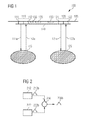
- FIG. 1 shows a smoke detector 100, which has a base plate 105.
- the base plate is a printed circuit board 105 or a suitable circuit carrier for receiving electronic and optoelectronic components. All attached to the circuit board 105 components are contacted in a manner not shown by means of conductors or electrical wire connections in a suitable manner.
- the smoke detector 100 comprises a first reflection light barrier 110 and a second reflection light barrier 120.
- the first reflection light barrier 110 has a first light emitter 111 and immediately adjacent thereto arranged in a common housing a first light receiver 112.
- the second reflection light barrier 120 has a second light transmitter 121 and immediately adjacent thereto arranged in a common housing a second light receiver 122.
- the first light emitter 111 transmits a first illumination light 111a substantially perpendicular to the plane of the printed circuit board 105.
- the first illumination light 111a is in a first detection space 115, in which, for example, smoke is located, at least partially backscattered by approximately 180 °.
- the backscattered light reaches the first light receiver 112 as the first measuring light 112a.
- the second light emitter 121 transmits a second illumination light 121a substantially perpendicular to the plane of the printed circuit board 105.
- the second illumination light 121a is at least partially backscattered by approximately 180 ° in a second detection space 125 in which, for example, smoke is located.
- the backscattered light reaches the second light receiver 122 as the second measuring light 122a.
- the smoke detector 100 also has a subtraction unit 136, which forms a difference signal from the output signals of the two light receivers 112 and 122. This difference signal is supplied to a data processing device 135 of the smoke detector 100.
- a control device 130 is provided, which is coupled to the two light transmitters 111 and 121.
- the two light transmitters 111 and 121 can be activated or switched on independently of each other.
- All of the components 110, 120, 130, 135 and 136 of the smoke detector 100 are mounted on the circuit board 105 and electrically contacted in a suitable manner. As a result, the smoke detector 100 can be realized in a very flat design. The height of the smoke detector 100 is determined only by the thickness of the printed circuit board 105 and by the components 110, 120, 130, 135 and 136.
- all components 110, 120, 130, 135 and 136 are so-called surface mount technology (SMD) components.
- SMD surface mount technology
- an overall height of only 2.1 mm can be achieved.
- the total height results from the distance between the top of the circuit board 105 and the in FIG. 1 provided with the reference numeral 140 lower surface of the smoke detector.
- the light-active surfaces of the light emitters 111, 121 and the light receivers 112, 122 coincide with the surface 140. This means that no further parts of the smoke detector 100 are located between these light-active surfaces and the respective detection space 115, 125.
- covers or housing parts Such covers, which are often provided in known smoke detectors for the purpose of soil repellence, but are not required in many applications, especially in the home area.
- light barriers which already have transparent protective layers for the light-active surfaces of the light emitters 111, 121 and the light receivers 112, 122, thereby providing at least some protection against soiling.
- the described smoke detector 100 with two mutually parallel reflection light barriers has the advantage that it has no optical elements such as lenses or mirrors.
- the smoke detector can be produced in a particularly simple manner with inexpensive components.
- no special mounting tolerances are to be observed. All components required for the smoke detector are mass-produced, which are inexpensive to procure.
- the parallel light rays 111a, 112a, 121a, 122a in principle present the danger that far away solid objects could be interpreted as smoke.
- An objective object accidentally brought into the detection space in the vicinity of the smoke detector 100 can be distinguished well from a smoke signal on the basis of the very strong backscatter signal become.
- far away scattering objects, which are in the field of vision of the smoke detector, due to their mostly diffuse backscattering provide only a weak signal and are often no longer reliably distinguishable from smoke with the above criterion.
- both light receivers 112 and 122 are activated.
- both light receivers 112 and 122 at least approximately the same signal, then it is a distant echo of an object that is outside the detection space in the field of view of the smoke detector.
- This echo may originate, for example, from a bottom surface of the room monitored by the smoke detector 100 and not from smoke particles.
- Smoke particles would namely, in particular at a ceiling mounting of the smoke detector 100 are at least partially in the vicinity of the smoke detector 100, so that in this case the signals of the two light receivers 112 and 122 would have different strengths.
- FIG. 2 shows the already in FIG. 1 shown subtraction unit, which is now provided with the reference numeral 236.
- a "minus input” of the subtraction unit 236 is supplied with a second output signal 222b of the second light receiver, which in FIG. 2 is provided with the reference numeral 222.
- a difference signal 236b is formed, which is a in FIG. 2 not shown data processing device is supplied.
- the difference signal 236b can be evaluated in the data processing device as described above.
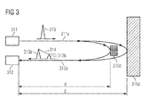
- FIG. 3 illustrates in a schematic representation the temporal broadening or structuring of a light pulse as a result of the scattering at various spatially distributed objects 315a and 315b.
- the articles 315a and 315b are expressly not smoke. From the degree of temporal broadening or the temporal structuring conclusions about spatial distribution of the subject scattering objects 315a and 315b can be obtained.
- a light emitter 311 emits an illumination light 311a which has at least one short light pulse 313.
- This light pulse 313 is then scattered back on the objects 315a and 315b in the field of view of the detector by approximately 180 degrees.
- the backscatter occurs on all possible objects within the field of view of the detector 311, 312.
- An exemplary object 315b is located at a distance d from the light emitter 311, the other exemplary object 315a is at a distance d 'from the light emitter 311.
- the object 315a is the floor of a monitored space
- the article 315b may be any article such as a piece of furniture that is permanently or temporarily located between the floor 315a and the smoke detector 311, 312.
- the light pulse 313 initially strikes the second object 315b at a distance d from the light emitter. In this case, part of the light energy is backscattered, so that the measurement light 312a, which strikes the light receiver 312, has a first backscatter pulse 313a. Thereafter, the now slightly attenuated light pulse 313 hits the first object or the bottom 315a, which is located at a distance d 'from the light emitter. Also at the bottom 315a, part of the light energy is scattered back again, so that the measurement light 312a has a second backscatter pulse 313b.
- the resulting total backscatter pulse is significantly widened compared to the input light pulse 313. Due to the absorption by smoke possibly located in the field of vision of the detector, the intensity of the later backscatter pulses can be reduced in comparison to the backscatter pulses previously applied to the light receiver 312. This results in an asymmetrical shape or an asymmetrical time course of the total backscatter pulse, which in FIG. 3 is provided with the reference numeral 314.
- any smoke in the field of view of the detector which is located at a distance of typically more than a few centimeters from the smoke detector 311, 312, does not make any significant contribution to the received optical backscatter signal.
- each input light pulse 313 can generate a plurality of backscatter pulses 313a, 313b,..., Which originate from the spatially distributed objects 315a, 315b.
- the farther an object is removed the more the trailing light beam 311a is attenuated by scattering and absorption of smoke particles possibly present in the room air.
- the echo of the more distant objects also arrives later at the light receiver 312. Based on the time course of the received light pulse thus the spatial distribution or arrangement of the objects located in the field of view of the smoke detector can be determined.
- the transit time of the light pulse from the transmission to the reception of the backscattered light pulse 314 can also be measured, and from this the distance between the light emitter 311 or the light receiver 312 and the objects 315a and 315b can be calculated.
Landscapes
- Physics & Mathematics (AREA)
- General Physics & Mathematics (AREA)
- Engineering & Computer Science (AREA)
- Computer Security & Cryptography (AREA)
- Chemical & Material Sciences (AREA)
- Analytical Chemistry (AREA)
- Business, Economics & Management (AREA)
- Emergency Management (AREA)
- Fire-Detection Mechanisms (AREA)
- Investigating Or Analysing Materials By Optical Means (AREA)
- Geophysics And Detection Of Objects (AREA)
Priority Applications (8)
| Application Number | Priority Date | Filing Date | Title |
|---|---|---|---|
| EP08101743A EP2093732A1 (fr) | 2008-02-19 | 2008-02-19 | Dispositif et procédé de détection de fumée à l'aide de l'évaluation collective de deux signaux à rétrodiffusion optiques |
| CN200980105643.XA CN101952861B (zh) | 2008-02-19 | 2009-02-19 | 对传感器装置中的两个接收设备的输出信号之间的差信号的分析 |
| PCT/EP2009/052002 WO2009103777A1 (fr) | 2008-02-19 | 2009-02-19 | Évaluation d'un signal différentiel entre deux signaux de sortie de deux dispositifs de réception situés dans un dispositif de détection |
| CNA2009101307088A CN101515400A (zh) | 2008-02-19 | 2009-02-19 | 通过分析两个光学反向散射信号检测烟雾的装置和方法 |
| HK11107225.9A HK1153301B (en) | 2008-02-19 | 2009-02-19 | Evaluation of a difference signal between output signals of two receiving devices in a sensor apparatus |
| US12/389,081 US20090256714A1 (en) | 2008-02-19 | 2009-02-19 | Device and Method for Detecting Smoke by Joint Evaluation of Two Optical Backscatter Signals |
| EP09713205A EP2252984B1 (fr) | 2008-02-19 | 2009-02-19 | Évaluation d'un signal différentiel entre deux signaux de sortie de deux dispositifs de réception situés dans un dispositif de détection |
| US12/735,844 US8546740B2 (en) | 2008-02-19 | 2009-02-19 | Evaluation of a difference signal between output signals of two receiving devices in a sensor apparatus |
Applications Claiming Priority (1)
| Application Number | Priority Date | Filing Date | Title |
|---|---|---|---|
| EP08101743A EP2093732A1 (fr) | 2008-02-19 | 2008-02-19 | Dispositif et procédé de détection de fumée à l'aide de l'évaluation collective de deux signaux à rétrodiffusion optiques |
Publications (1)
| Publication Number | Publication Date |
|---|---|
| EP2093732A1 true EP2093732A1 (fr) | 2009-08-26 |
Family
ID=39531402
Family Applications (2)
| Application Number | Title | Priority Date | Filing Date |
|---|---|---|---|
| EP08101743A Withdrawn EP2093732A1 (fr) | 2008-02-19 | 2008-02-19 | Dispositif et procédé de détection de fumée à l'aide de l'évaluation collective de deux signaux à rétrodiffusion optiques |
| EP09713205A Active EP2252984B1 (fr) | 2008-02-19 | 2009-02-19 | Évaluation d'un signal différentiel entre deux signaux de sortie de deux dispositifs de réception situés dans un dispositif de détection |
Family Applications After (1)
| Application Number | Title | Priority Date | Filing Date |
|---|---|---|---|
| EP09713205A Active EP2252984B1 (fr) | 2008-02-19 | 2009-02-19 | Évaluation d'un signal différentiel entre deux signaux de sortie de deux dispositifs de réception situés dans un dispositif de détection |
Country Status (4)
| Country | Link |
|---|---|
| US (2) | US8546740B2 (fr) |
| EP (2) | EP2093732A1 (fr) |
| CN (2) | CN101515400A (fr) |
| WO (1) | WO2009103777A1 (fr) |
Cited By (6)
| Publication number | Priority date | Publication date | Assignee | Title |
|---|---|---|---|---|
| DE102015004458A1 (de) | 2014-06-26 | 2015-12-31 | Elmos Semiconductor Aktiengesellschaft | Vorrichtung und Verfahren für einen klassifizierenden, rauchkammerlosen Luftzustandssensor |
| DE102014019773A1 (de) | 2014-12-17 | 2016-06-23 | Elmos Semiconductor Aktiengesellschaft | Vorrichtung und Verfahren zur Unterscheidung von festen Objekten, Kochdunst und Rauch mittels des Displays eines Mobiltelefons |
| DE102014019172A1 (de) | 2014-12-17 | 2016-06-23 | Elmos Semiconductor Aktiengesellschaft | Vorrichtung und Verfahren zur Unterscheidung von festen Objekten, Kochdunst und Rauch mit einem kompensierenden optischen Messsystem |
| EP2423895B1 (fr) | 2010-08-26 | 2017-03-08 | Siemens Schweiz AG | Alarme incendie à lumière diffusée dotée de moyens de suppression d'une alerte acoustique en cas de faible tension d'alimentation |
| DE102019219200A1 (de) * | 2019-12-10 | 2021-06-10 | Siemens Schweiz Ag | Rauchdetektionseinheit für einen Brandmelder mit Grundpulsunterdrückung sowie geeignetes Verfahren zur Rauchdetektion |
| WO2021115728A1 (fr) | 2019-12-10 | 2021-06-17 | Siemens Schweiz Ag | Unité de détection de fumée pour une alarme incendie à suppression d'impulsions de base, et procédé approprié de détection de fumée |
Families Citing this family (30)
| Publication number | Priority date | Publication date | Assignee | Title |
|---|---|---|---|---|
| US8948273B2 (en) * | 2007-09-17 | 2015-02-03 | J. Craig Oxford | Method and apparatus for wired signal transmission |
| DK2093734T3 (da) * | 2008-02-19 | 2011-10-10 | Siemens Ag | Røgalarm med tidslig fortolkning af et tilbagekoblingssignal, testfremgangsmåde til funktionsdygtighed af en røgalarm |
| WO2011100225A1 (fr) * | 2010-02-09 | 2011-08-18 | Conocophillips Company | Contrôle automatisé de torche |
| JP5691594B2 (ja) * | 2011-02-09 | 2015-04-01 | 富士ゼロックス株式会社 | 検知装置および処理システム |
| DE102011083939B4 (de) * | 2011-09-30 | 2014-12-04 | Siemens Aktiengesellschaft | Auswerten von Streulichtsignalen bei einem optischen Gefahrenmelder und Ausgeben sowohl eines gewichteten Rauchdichtesignals als auch eines gewichteten Staub-/Dampfdichte-Signals |
| EP2608174B1 (fr) * | 2011-12-20 | 2016-10-19 | Siemens Schweiz AG | Procédé de reconnaissance d'un objet parasite dans un volume de diffusion d'un détecteur d'incendie optique et détecteur d'incendie optique |
| JP2013197243A (ja) * | 2012-03-19 | 2013-09-30 | Rohm Co Ltd | 光センサ及びその出力回路 |
| US8952821B2 (en) | 2012-04-29 | 2015-02-10 | Valor Fire Safety, Llc | Smoke detector utilizing ambient-light sensor, external sampling volume, and internally reflected light |
| US9140646B2 (en) | 2012-04-29 | 2015-09-22 | Valor Fire Safety, Llc | Smoke detector with external sampling volume using two different wavelengths and ambient light detection for measurement correction |
| US8907802B2 (en) | 2012-04-29 | 2014-12-09 | Valor Fire Safety, Llc | Smoke detector with external sampling volume and ambient light rejection |
| CN102789671B (zh) * | 2012-06-21 | 2017-02-22 | 江苏中瀚通讯技术有限公司 | 一种免维护式光电式烟雾探测器及其测试过程 |
| US9111426B2 (en) * | 2012-07-09 | 2015-08-18 | Sfjc, Llc | Recreational smoking monitor system for use in occupied spaces |
| DE102013101280B4 (de) * | 2013-02-08 | 2025-02-20 | Schako Kg | Rauchmelder |
| CN105849787B (zh) | 2013-10-30 | 2019-02-15 | 瓦洛尔消防安全有限责任公司 | 具有外部采样体积和环境光抑制的烟雾探测器 |
| EP3167309B1 (fr) | 2014-07-11 | 2021-02-17 | Carrier Corporation | Technique de positionnement lidar sans encodeur à des fins de détection et d'alarme |
| CN105299718A (zh) * | 2014-08-01 | 2016-02-03 | 青岛海尔智能技术研发有限公司 | 自动调节风速的抽油烟机 |
| EP3073458A1 (fr) * | 2015-03-23 | 2016-09-28 | Siemens Schweiz AG | Dispositif d'alerte d'incendie doté d'un agencement à écran diffusant dans la zone d'un orifice d'entrée de fumée destiné à la surveillance de l'encrassement |
| US10769921B2 (en) | 2016-08-04 | 2020-09-08 | Carrier Corporation | Smoke detector |
| CA3043500A1 (fr) * | 2016-11-11 | 2018-05-17 | Carrier Corporation | Detection basee sur des fibres optiques haute sensibilite |
| CN106534415B (zh) * | 2016-12-06 | 2023-04-07 | Oppo广东移动通信有限公司 | 传感器组件、盖板组件、终端及接近状态检测方法 |
| WO2018170232A1 (fr) * | 2017-03-16 | 2018-09-20 | Symmetry Sensors, Inc. | Systèmes et procédés de perception optique |
| US10605924B2 (en) * | 2017-08-02 | 2020-03-31 | GM Global Technology Operations LLC | Method and apparatus cross segment detection in a lidar system |
| DE102018125494A1 (de) * | 2018-10-15 | 2020-04-16 | Bombardier Transportation Gmbh | Rauchmelder zum streckenweisen Detektieren von Rauch, sowie Fahrzeug aufweisend einen Rauchmelder |
| EP3783341A1 (fr) * | 2019-08-20 | 2021-02-24 | FRAUNHOFER-GESELLSCHAFT zur Förderung der angewandten Forschung e.V. | Détecteur de gaz et procédé de détection d'un gaz cible |
| DE102019132239A1 (de) * | 2019-11-28 | 2021-06-02 | Valeo Schalter Und Sensoren Gmbh | Verfahren zur Nebelerfassung für ein Fahrzeug durch einen Nebeldetektor mit einer speziell geformten Linse |
| DE102020201637A1 (de) * | 2020-02-11 | 2021-08-12 | Ibeo Automotive Systems GmbH | Verfahren zur Analyse von Rückstreuungs-Histogrammdaten bei einem optischen Pulslaufzeit-Verfahren und Vorrichtung zur Datenverarbeitung |
| CN111295021B (zh) * | 2020-03-12 | 2022-04-19 | 佛山市南海柏斯光照明有限公司 | 基于物理联网的灯光控制方法、装置、系统及存储介质 |
| US11615683B2 (en) * | 2020-04-01 | 2023-03-28 | Carrier Corporation | Surface mount back scatter photo-electric smoke detector |
| DE102020120698A1 (de) | 2020-08-05 | 2022-02-10 | Valeo Schalter Und Sensoren Gmbh | Kompensation eines Ultraschallwandlers mit veränderlicher Kompensationsinduktivität |
| CN117523795B (zh) * | 2024-01-08 | 2024-03-12 | 电子科技大学 | 一种基于物联网的弱电桥架线路布设异常预警方法和系统 |
Citations (6)
| Publication number | Priority date | Publication date | Assignee | Title |
|---|---|---|---|---|
| EP0472039A2 (fr) | 1990-08-23 | 1992-02-26 | Nohmi Bosai Ltd. | Procédé et dispositif pour la détection d'incendie |
| EP1039426A2 (fr) | 1999-03-22 | 2000-09-27 | Schako Metallwarenfabrik Ferdinand Schad Kg | Dispositif pour détecter de la fumée |
| EP1349127A1 (fr) * | 2002-03-28 | 2003-10-01 | Siemens Building Technologies AG | Capteur de fumée selon le principe d'extinction et son utilisation |
| WO2005051053A2 (fr) | 2003-11-18 | 2005-06-02 | Robert Bosch Gmbh | Detecteur d'incendie |
| DE102004001699A1 (de) | 2004-01-13 | 2005-08-04 | Robert Bosch Gmbh | Brandmelder |
| EP1783713A1 (fr) * | 2005-11-04 | 2007-05-09 | Siemens Schweiz AG | Prévention contre la manipulation abusive d'un détecteur de feu |
Family Cites Families (14)
| Publication number | Priority date | Publication date | Assignee | Title |
|---|---|---|---|---|
| JPS5462800A (en) * | 1977-10-28 | 1979-05-21 | Nittan Co Ltd | Light type smoke sensor having trouble detecting function |
| US4220857A (en) * | 1978-11-01 | 1980-09-02 | Systron-Donner Corporation | Optical flame and explosion detection system and method |
| GB2123548B (en) | 1982-07-14 | 1985-09-04 | Chloride Group Plc | Suspended particle detector |
| US4857895A (en) * | 1987-08-31 | 1989-08-15 | Kaprelian Edward K | Combined scatter and light obscuration smoke detector |
| US5140168A (en) | 1990-12-03 | 1992-08-18 | Great Lakes Instruments, Inc. | Turbidimeter signal processing circuit using alternating light sources |
| SE470168B (sv) * | 1992-04-27 | 1993-11-22 | Whirlpool Int | Rök/ångdetektor för mikrovågsugn |
| US5352901A (en) * | 1993-04-26 | 1994-10-04 | Cummins Electronics Company, Inc. | Forward and back scattering loss compensated smoke detector |
| US5576697A (en) * | 1993-04-30 | 1996-11-19 | Hochiki Kabushiki Kaisha | Fire alarm system |
| JPH1123458A (ja) | 1997-05-08 | 1999-01-29 | Nittan Co Ltd | 煙感知器および監視制御システム |
| US6611320B1 (en) * | 1999-09-08 | 2003-08-26 | Optoq Ab | Method and apparatus |
| AUPQ553800A0 (en) * | 2000-02-10 | 2000-03-02 | Cole, Martin Terence | Improvements relating to smoke detectors particularily duct monitored smoke detectors |
| US7564365B2 (en) * | 2002-08-23 | 2009-07-21 | Ge Security, Inc. | Smoke detector and method of detecting smoke |
| TW200821995A (en) * | 2006-09-07 | 2008-05-16 | Siemens Schweiz Ag | Improvement(s) related to particle monitors and method(s) therefor |
| US20100194574A1 (en) * | 2009-01-30 | 2010-08-05 | David James Monk | Particle detection system and method of detecting particles |
-
2008
- 2008-02-19 EP EP08101743A patent/EP2093732A1/fr not_active Withdrawn
-
2009
- 2009-02-19 WO PCT/EP2009/052002 patent/WO2009103777A1/fr not_active Ceased
- 2009-02-19 US US12/735,844 patent/US8546740B2/en active Active
- 2009-02-19 EP EP09713205A patent/EP2252984B1/fr active Active
- 2009-02-19 US US12/389,081 patent/US20090256714A1/en not_active Abandoned
- 2009-02-19 CN CNA2009101307088A patent/CN101515400A/zh active Pending
- 2009-02-19 CN CN200980105643.XA patent/CN101952861B/zh not_active Expired - Fee Related
Patent Citations (6)
| Publication number | Priority date | Publication date | Assignee | Title |
|---|---|---|---|---|
| EP0472039A2 (fr) | 1990-08-23 | 1992-02-26 | Nohmi Bosai Ltd. | Procédé et dispositif pour la détection d'incendie |
| EP1039426A2 (fr) | 1999-03-22 | 2000-09-27 | Schako Metallwarenfabrik Ferdinand Schad Kg | Dispositif pour détecter de la fumée |
| EP1349127A1 (fr) * | 2002-03-28 | 2003-10-01 | Siemens Building Technologies AG | Capteur de fumée selon le principe d'extinction et son utilisation |
| WO2005051053A2 (fr) | 2003-11-18 | 2005-06-02 | Robert Bosch Gmbh | Detecteur d'incendie |
| DE102004001699A1 (de) | 2004-01-13 | 2005-08-04 | Robert Bosch Gmbh | Brandmelder |
| EP1783713A1 (fr) * | 2005-11-04 | 2007-05-09 | Siemens Schweiz AG | Prévention contre la manipulation abusive d'un détecteur de feu |
Cited By (6)
| Publication number | Priority date | Publication date | Assignee | Title |
|---|---|---|---|---|
| EP2423895B1 (fr) | 2010-08-26 | 2017-03-08 | Siemens Schweiz AG | Alarme incendie à lumière diffusée dotée de moyens de suppression d'une alerte acoustique en cas de faible tension d'alimentation |
| DE102015004458A1 (de) | 2014-06-26 | 2015-12-31 | Elmos Semiconductor Aktiengesellschaft | Vorrichtung und Verfahren für einen klassifizierenden, rauchkammerlosen Luftzustandssensor |
| DE102014019773A1 (de) | 2014-12-17 | 2016-06-23 | Elmos Semiconductor Aktiengesellschaft | Vorrichtung und Verfahren zur Unterscheidung von festen Objekten, Kochdunst und Rauch mittels des Displays eines Mobiltelefons |
| DE102014019172A1 (de) | 2014-12-17 | 2016-06-23 | Elmos Semiconductor Aktiengesellschaft | Vorrichtung und Verfahren zur Unterscheidung von festen Objekten, Kochdunst und Rauch mit einem kompensierenden optischen Messsystem |
| DE102019219200A1 (de) * | 2019-12-10 | 2021-06-10 | Siemens Schweiz Ag | Rauchdetektionseinheit für einen Brandmelder mit Grundpulsunterdrückung sowie geeignetes Verfahren zur Rauchdetektion |
| WO2021115728A1 (fr) | 2019-12-10 | 2021-06-17 | Siemens Schweiz Ag | Unité de détection de fumée pour une alarme incendie à suppression d'impulsions de base, et procédé approprié de détection de fumée |
Also Published As
| Publication number | Publication date |
|---|---|
| CN101515400A (zh) | 2009-08-26 |
| US20090256714A1 (en) | 2009-10-15 |
| EP2252984A1 (fr) | 2010-11-24 |
| WO2009103777A1 (fr) | 2009-08-27 |
| US20110108748A1 (en) | 2011-05-12 |
| CN101952861B (zh) | 2015-11-25 |
| EP2252984B1 (fr) | 2012-07-25 |
| US8546740B2 (en) | 2013-10-01 |
| CN101952861A (zh) | 2011-01-19 |
| HK1153301A1 (zh) | 2012-03-23 |
Similar Documents
| Publication | Publication Date | Title |
|---|---|---|
| EP2252984B1 (fr) | Évaluation d'un signal différentiel entre deux signaux de sortie de deux dispositifs de réception situés dans un dispositif de détection | |
| EP2093734B1 (fr) | Détecteur de fumée doté d'une évaluation temporelle d'un signal de rétrodiffusion, procédé de test pour la capacité fonctionnelle d'un détecteur de fumée | |
| EP2093733B1 (fr) | Détection de fumée à l'aide de deux mesures à lumière diffusée spectrales différentes | |
| EP2541273B1 (fr) | Détection et détermination de distance d'objets | |
| EP3029647B1 (fr) | Détecteur de fumée à écran diffusant ouvert, notamment équipé d'une LED Side-looker | |
| DE10229408B4 (de) | Optischer Sensor | |
| EP3091369B1 (fr) | Lecteur laser | |
| EP2608174B1 (fr) | Procédé de reconnaissance d'un objet parasite dans un volume de diffusion d'un détecteur d'incendie optique et détecteur d'incendie optique | |
| EP1723446A1 (fr) | Dispositif de controle d'acces | |
| DE102015118258B3 (de) | Laserscanner und Verfahren zur Überprüfung von dessen Funktionsfähigkeit | |
| DE9321155U1 (de) | Laserabstandsermittlungsvorrichtung | |
| EP2043068B1 (fr) | Dispositif destiné à la surveillance d'une alerte d'incendie et procédé de configuration et alerte d'incendie | |
| EP3435117A1 (fr) | Capteur et procédé de détection et de détermination des distances entre des objets | |
| DE102018132473B4 (de) | Optoelektronischer Sensor und Verfahren zur Erfassung eines Objekts | |
| EP2159603B1 (fr) | Procédé de détection d'objets et capteur de détection d'objets | |
| EP3270182A1 (fr) | Capteur optoélectronique et procédé de détection d'objets dans une zone de surveillance | |
| DE102017107667A1 (de) | Laserscanner und Verfahren zur Überprüfung der Funktionsfähigkeit | |
| EP2093731A1 (fr) | Détecteur de fumée optique linéaire doté de plusieurs rayons partiels | |
| EP2703837B1 (fr) | Scanner laser de sécurité | |
| DE102016103028A1 (de) | Vorrichtung zum Überwachen eines Überwachungsbereichs | |
| DE102017125587A1 (de) | Optischer Sensor zum Nachweis von Objekten in einem Erfassungsbereich | |
| DE102009040325A1 (de) | Sensorsystem zur Erfassung von Umgebungsobjekten | |
| DE102019111216B4 (de) | Optischer Scanner | |
| DE202008009090U1 (de) | Optoelektronischer Sensor | |
| DE102004053219B3 (de) | Optischer Sensor |
Legal Events
| Date | Code | Title | Description |
|---|---|---|---|
| PUAI | Public reference made under article 153(3) epc to a published international application that has entered the european phase |
Free format text: ORIGINAL CODE: 0009012 |
|
| AK | Designated contracting states |
Kind code of ref document: A1 Designated state(s): AT BE BG CH CY CZ DE DK EE ES FI FR GB GR HR HU IE IS IT LI LT LU LV MC MT NL NO PL PT RO SE SI SK TR |
|
| AX | Request for extension of the european patent |
Extension state: AL BA MK RS |
|
| AKX | Designation fees paid | ||
| REG | Reference to a national code |
Ref country code: DE Ref legal event code: 8566 |
|
| STAA | Information on the status of an ep patent application or granted ep patent |
Free format text: STATUS: THE APPLICATION IS DEEMED TO BE WITHDRAWN |
|
| 18D | Application deemed to be withdrawn |
Effective date: 20100227 |