EP2093822A2 - Structure d'empilement de piles à combustible - Google Patents
Structure d'empilement de piles à combustible Download PDFInfo
- Publication number
- EP2093822A2 EP2093822A2 EP09002283A EP09002283A EP2093822A2 EP 2093822 A2 EP2093822 A2 EP 2093822A2 EP 09002283 A EP09002283 A EP 09002283A EP 09002283 A EP09002283 A EP 09002283A EP 2093822 A2 EP2093822 A2 EP 2093822A2
- Authority
- EP
- European Patent Office
- Prior art keywords
- pressure
- fuel cell
- cell stack
- end plate
- supporting
- Prior art date
- Legal status (The legal status is an assumption and is not a legal conclusion. Google has not performed a legal analysis and makes no representation as to the accuracy of the status listed.)
- Withdrawn
Links
Images


Classifications
-
- H—ELECTRICITY
- H01—ELECTRIC ELEMENTS
- H01M—PROCESSES OR MEANS, e.g. BATTERIES, FOR THE DIRECT CONVERSION OF CHEMICAL ENERGY INTO ELECTRICAL ENERGY
- H01M8/00—Fuel cells; Manufacture thereof
- H01M8/24—Grouping of fuel cells, e.g. stacking of fuel cells
- H01M8/2465—Details of groupings of fuel cells
- H01M8/247—Arrangements for tightening a stack, for accommodation of a stack in a tank or for assembling different tanks
- H01M8/2475—Enclosures, casings or containers of fuel cell stacks
-
- H—ELECTRICITY
- H01—ELECTRIC ELEMENTS
- H01M—PROCESSES OR MEANS, e.g. BATTERIES, FOR THE DIRECT CONVERSION OF CHEMICAL ENERGY INTO ELECTRICAL ENERGY
- H01M8/00—Fuel cells; Manufacture thereof
- H01M8/02—Details
- H01M8/0202—Collectors; Separators, e.g. bipolar separators; Interconnectors
- H01M8/0204—Non-porous and characterised by the material
-
- H—ELECTRICITY
- H01—ELECTRIC ELEMENTS
- H01M—PROCESSES OR MEANS, e.g. BATTERIES, FOR THE DIRECT CONVERSION OF CHEMICAL ENERGY INTO ELECTRICAL ENERGY
- H01M8/00—Fuel cells; Manufacture thereof
- H01M8/24—Grouping of fuel cells, e.g. stacking of fuel cells
- H01M8/2465—Details of groupings of fuel cells
- H01M8/247—Arrangements for tightening a stack, for accommodation of a stack in a tank or for assembling different tanks
- H01M8/248—Means for compression of the fuel cell stacks
-
- Y—GENERAL TAGGING OF NEW TECHNOLOGICAL DEVELOPMENTS; GENERAL TAGGING OF CROSS-SECTIONAL TECHNOLOGIES SPANNING OVER SEVERAL SECTIONS OF THE IPC; TECHNICAL SUBJECTS COVERED BY FORMER USPC CROSS-REFERENCE ART COLLECTIONS [XRACs] AND DIGESTS
- Y02—TECHNOLOGIES OR APPLICATIONS FOR MITIGATION OR ADAPTATION AGAINST CLIMATE CHANGE
- Y02E—REDUCTION OF GREENHOUSE GAS [GHG] EMISSIONS, RELATED TO ENERGY GENERATION, TRANSMISSION OR DISTRIBUTION
- Y02E60/00—Enabling technologies; Technologies with a potential or indirect contribution to GHG emissions mitigation
- Y02E60/30—Hydrogen technology
- Y02E60/50—Fuel cells
Definitions
- the present invention relates to a fuel cell assembly structure, and in particular to a pressure-supporting assembly structure for a fuel cell stack.
- Fuel cells are a device that makes use of electro-chemical reaction between a fuel containing hydrogen and air to generate electrical power and water.
- the fuel cell comprises a plurality of fuel cell units each comprising a proton exchange membrane set at a center and two catalyst layers arranged on opposite sides and further comprising a gas diffusion layer (GDL) set outside each catalyst layer and an anode bipolar plate and a cathode bipolar plate respectively set on the outer sides, all the components being tightly fixed together with a predetermined contact pressure therebetween to form a single fuel cell unit.
- GDL gas diffusion layer
- the pressure of the fuel cell stack must be maintained within a fixed range to avoid excessively high contact resistance that affects the conversion efficiency of the fuel cell.
- a plurality of fuel cell units is stacked and connected serially to form a fuel cell stack, opposite ends of which in the longitudinal direction are respectively provided with two end plates and a plurality of tie rods extending through circumferential edges of the two end plates that fix the fuel cell stack between the end plates.
- US Patent No. 5,993,987 discloses a compression band for electro-chemical fuel cell stack, wherein the fuel cell stack comprises a plurality of fuel cell assemblies that are interposed between a pair of end plate assemblies.
- the pair of end plate assemblies includes a first end plate and a second end plate.
- Each single fuel cell assembly includes an anode layer and a cathode layer.
- the end plate assemblies further comprise a resilient compression assembly that comprises an elongate compression band circumscribing in a single pass the first and second end plate assemblies to cause the first and second end plate assemblies to apply a compression force to the fuel cell stack thereby securely holding the fuel cell assemblies of the fuel cell stack.
- a resilient compression assembly that comprises an elongate compression band circumscribing in a single pass the first and second end plate assemblies to cause the first and second end plate assemblies to apply a compression force to the fuel cell stack thereby securely holding the fuel cell assemblies of the fuel cell stack.
- the fuel cell assembly may undergo deformation or warping, and even destruction of the construction thereof.
- the performance of the individual fuel cell units is affected.
- the engagement tightness between the fuel cell assemblies may be poor, leading to leakage of water or gas and causing increased contact resistance between layers of the fuel cell stack, and as a consequence, the performance of the fuel cell stack deteriorates.
- the individual fuel cell assembly contained in the fuel cell stack has a poor pressure resistance, so that in practical application, an additionally provided enclosure and protection structure, such as a protection frame or a protection shell, must be employed to protect the stacked components of a completely assembled fuel cell stack, otherwise the fuel cell stack may be susceptible to risks of being damaged, distortion and deformation when impacted or hit.
- an additionally provided enclosure and protection structure such as a protection frame or a protection shell
- an objective of the present invention is to provide a pressure-supporting assembly structure for a fuel cell stack, which offers certain protection to the components of the fuel cell stack and simplifies maintenance and repairing.
- Another objective of the present invention is to provide a pressure-supporting assembly structure for a fuel cell stack, which provides an optimum contact pressure between individual fuel cell units of the fuel cell stack.
- a further objective of the present invention is to provide a pressure-supporting assembly structure for a fuel cell stack, which adjusts the contact pressure between fuel cell units and end plates of the fuel cell stack so as to make the application of the fuel cell flexible.
- a pressure-supporting structure for a fuel cell stack comprising a fuel cell stack, a first pressure-supporting end plate assembly, a first current collector plate, a second pressure-supporting end plate assembly, a second current collector plate, a pressure-supporting structure, and a pressure-applying structure.
- the fuel cell stack comprises a first electrode side, a second electrode side and at least one fuel cell unit.
- the first pressure-supporting end plate assembly is coupled to the first electrode side of the fuel cell stack through a first end plate and the first current collector plate
- the second pressure-supporting end plate assembly is coupled to the second electrode side of the fuel cell stack through a second end plate and the second current collector plate.
- the pressure-applying structure is comprised of a pressure-applying plate and a pair of side plates extending from opposite side edges of the pressure-applying plate.
- the two side plates form an open end therebetween.
- the pressure-supporting structure is interposed between the first end plate and the coupling section and applies a pressure to the fuel cell stack in a direction from the first pressure-supporting end plate assembly toward the second pressure-supporting end plate assembly in order to provide the requisite contact pressure to each individual fuel cell unit of the fuel cell stack.
- a modularized arrangement of the fuel cell stack assembly structure is provided, which effectively enhances the assembling efficiency of the fuel cell stack, whereby when abnormality or damage occurs in the assembly structure of the present invention, it only needs to replace the problematic fuel cell unit and the drawbacks that the conventional techniques encountered by replacement of the whole fuel cell stack that inevitably increases the costs can be eliminated.
- the present invention employs only a single pressure-applying structure having an open end, together with a plurality of resilient elements assembled inside the assembly structure, to fulfill the objective of supplying a requisite pressure to the fuel cell stack.
- such an arrangement is capable of uniformly applying pressure, so that the optimum contact pressure can be provided between the fuel cell units of the fuel cell stack.
- Problems of for example water leakage, gas leakage, and increased contact resistance between layers of the fuel cell stack resulting from poor engagement tightness of the fuel cell stack caused by insufficient contact pressure, or problems of deformation and warping of the individual fuel cell units or even destruction of the construction of the fuel cell stack caused by excessive pressure that lead to deterioration of fuel cell performance occurring in the conventional techniques can thus be eliminated.
- Other conventional measures, such as tie rod are also problematic to the assembling of the fuel cell stack.
- the first pressure-supporting end plate assembly and the second pressure-supporting end plate assembly coupled to the two electrode sides of the fuel cell stack are both provided with cooling water inlet and outlet ports and hydrogen inlet and outlet ports, whereby the contact area for reaction is increased, the conductivity and permeability of the fuel cells stack are enhanced, and thus the performance of the fuel cell stack is improved.
- the pressure-applying structure can protect all the related structures of the fuel cell stack and provide certain protection to each related structure of the fuel cell to avoid damage, distortion, or detachment of the fuel cell stack caused by external impact or hit.
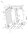
- Figure 1 is an exploded view of a first embodiment in accordance with the present invention
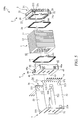
- Figure 2 is an exploded view of a portion of the structure of the present invention
- Figure 3 is a perspective view of the first embodiment of the present invention.
- Figure 4 is another perspective view of the first embodiment of the present invention taken at a different angle
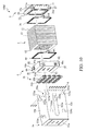
- Figure 5 is an exploded view of a second embodiment in accordance with the present invention.
- Figure 6 is an exploded view of a third embodiment in accordance with the present invention.
- Figure 7 is a bottom view of the third embodiment in accordance with the present invention.
- Figure 8 is an exploded view of a fourth embodiment in accordance with the present invention.
- Figure 9 is a perspective view of the fourth embodiment of the present invention.
- Figure 10 is an exploded view of a fifth embodiment in accordance with the present invention.
- Figure 11 is an exploded view of a sixth embodiment in accordance with the present invention.
- Figure 12 is a perspective view of the sixth embodiment of the present invention.
- the present invention provides a pressure-supporting assembly structure 100 for a fuel cell stack, which comprises a fuel cell stack 1 having a first electrode side 11 and a second electrode side 12 and being comprised of at least one fuel cell unit 13.
- the first electrode side 11 of the fuel cell stack 1 is coupled to a first pressure-supporting end plate assembly 2, with a first current collector plate 26 positioned therebetween.
- the first pressure-supporting end plate assembly 2 comprises a first end plate 20 and a coupling section 21, wherein the coupling section 21 has opposite side walls each forming a row of apertures 211, 212.
- the first end plate 20 and the coupling section 21 of the first pressure-supporting end plate assembly 2 are provided therebetween a pressure-supporting structure 3 (see Figure 2 ), which is comprised of a pressure-supporting plate 31 and a plurality of resilient elements 32.
- the pressure-supporting plate 31 forms a plurality of pressure-supporting holes 33 corresponding to the resilient elements 32 respectively for receiving the resilient elements 32 therein.
- the resilient elements 32 comprise disc springs, but can adopt other types of resilient elements, such as an elastic block, a spring plate, a piston, a polymer or fiber-reinforced composite material, or other chemical polymer, provided they offer a predetermined resilient behavior, and the selection is dependent on the applications.
- the first end plate 20 of the first pressure-supporting end plate assembly 2 further comprises a first side face 22 and a second side face 23.
- the two side faces forms corresponding cooling water inlet and outlet ports 24a, 24b, and corresponding hydrogen inlet and outlet ports 25a, 25b.
- the second electrode side 12 of the fuel cell stack 1 is coupled to a second pressure-supporting end plate assembly 4 with a second current collector plate 49 positioned therebetween.
- the second pressure-supporting end plate assembly 4 comprises a second end plate 40, which comprises a second end plate surface 41, a first side face 42, a second side face 43, a third side face 44, and a fourth side face 45.
- the first side face 42 and the second side face 43 respectively form corresponding cooling water inlet and outlet ports 46a, 46b and corresponding hydrogen inlet and outlet ports 47a, 47b.
- the third side face 44 and the fourth side face 45 respectively form air inlet and outlet ports 48a, 48b.
- a pressure-applying structure 5 is employed to combine and retain the fuel cell stack 1, the first pressure-supporting end plate assembly 2, the first current collector plate 26, the pressure-supporting structure 3, the second pressure-supporting end plate assembly 4, and the second current collector plate 49 together.
- the pressure-applying structure 5 is comprised of a pressure-applying plate 51 and a pair of side plates 52, 53 extending from opposite side edges of the pressure-applying plate 51.
- the two side plates 52, 53 form an open end 54 therebetween and each forms, at a location close to the open end 54, a row of positioning structures 521, 531 corresponding to the coupling section 21 of the first end plate 20.
- the positioning structures can be coupling holes.
- the side plate 52 forms a hollow section 522 at a central portion thereof to allow protruding ends 261, 491 of the first current collector plate 26 and the second current collector plate 49 to extend outward therethrough.
- the two side plates 52, 53 form guiding holes 523, 532, 524, 533 corresponding to the cooling water inlet and outlet ports 24a, 24b, 46a, 46b and also forms guiding holes 525, 534, 526, 535 corresponding to the hydrogen inlet and outlet ports 25a, 25b, 47a, 47b.
- the fuel cell stack 1, the first pressure-supporting end plate assembly 2, the first current collector plate 26, the pressure-supporting structure 3, the second pressure-supporting end plate assembly 4, the second current collector plate 49, and the pressure-applying structure 5 can be assembled together with (see Figures 3 and 4 ) so that the pressure-applying plate 51 of the pressure-applying structure 5 abuts against the second end plate surface 41 of the second pressure-supporting end plate assembly 4 and the protruding ends 261, 491 of the first current collector plate 26 and the second current collector plate 49 extending through the hollow section 522 of the side plate 52.
- a plurality of fasteners 6 are set to respectively engage the apertures 211, 212 of the coupling section 21 of the first pressure-supporting end plate assembly 2 via the positioning structures 521, 531 of the side plates 52, 53.
- the pressure-supporting structure 3 that is interposed between the first end plate 20 and the coupling section 21 of the first pressure-supporting end plate assembly 2 applies, via the first pressure-supporting end plate assembly 2, a pressure to the fuel cell stack 1 in a direction toward the second pressure-supporting end plate assembly 4 to provide the requisite contact pressure for individual fuel cell units 13.
- the second embodiment provides a pressure-supporting assembly structure 100a for a fuel cell stack, of which most of the components/parts are similar to the counterparts of the pressure-supporting assembly structure 100 of the first embodiment, so that identical components/parts are designated with the same reference numerals for simplicity and correspondence with each other.
- the difference between the first and second embodiments resides in that in the second embodiment, the side plates 52, 53 of the pressure-applying structure 5 form support flanges 55, 56 that respectively extend from ends of the side plates 52, 53 adjacent to the positioning structures 521, 531.
- the coupling section 21 of the first pressure-supporting end plate assembly 2 is positioned against the support flanges 55, 56 of the side plates 52, 53 of the pressure-applying structure 5 and in this way, the strength of the assembled structure of the fuel cell stack in accordance with the present invention is enhanced.
- the assembling process of the second embodiment is substantially identical to that of the first embodiment and thus no repeat of details is needed.
- the positioning structures 521, 531 may be alternatively or additionally formed on the support flanges 55, 56 and correspondingly, the apertures 211, 212 of the coupling section 21 of the first pressure-supporting end plate assembly 2 are made at corresponding locations and they are then jointed together by the fasteners 6.
- FIG. 6 and 7 shows, respectively, an exploded view and a bottom view of a third embodiment of the present invention.
- the third embodiment provides a pressure-supporting assembly structure 100b for a fuel cell stack, which comprises components/parts most of which are similar to the counterparts of the second embodiment, so that identical components/parts are designated with the same reference numerals for correspondence therebetween.
- the two side plates 52, 53 of the pressure-applying structure 5 are provided with retainers 57, 58 at free ends thereof respectively.
- the retainers 57, 58 form positioning structures 521, 531 respectively and ribs 571, 581.
- a pair of positioning bars 7, 7a is provided and extends between the first pressure-supporting end plate assembly 2 and the second pressure-supporting end plate assembly 4.
- the fuel cell stack 1, the first pressure-supporting end plate assembly 2, the first current collector plate 26, the pressure-supporting structure 3, the second pressure-supporting end plate assembly 4, the second current collector plate 49, the pressure-applying structure 5, and the positioning bars 7, 7a are assembled together by using a proper clamping jig, a plurality of fasteners 6a are set to engage a coupling section 21a of the first pressure-supporting end plate assembly 2 through the positioning structures 521, 531 of the retainers 57, 58.
- the resilient elements 32 that are interposed between the first end plate 20 and the coupling section 21a of the first pressure-supporting end plate assembly 2 may apply, via the first pressure-supporting end plate assembly 2, a pressure to the fuel cell stack 1 in a direction toward the second pressure-supporting end plate assembly 4.
- the depth of the fasteners 6a set in the positioning structures 521, 531 the contact pressure applied between the fuel cell units 13 and the two end plates 20, 40 can be properly adjusted.
- the pressure-applying structure 5 of the instant embodiment can be modified to comprise the support flanges as discussed with reference to Figure 5 .
- the retainers 57, 58 that are set at the free ends of the two side plates 52, 53 are respectively provided with protective covers 8, 8a for protection of the fasteners 6a that are set in the positioning structures 521, 531.
- the fourth embodiment of the present invention provides a pressure-supporting assembly structure 100c for a fuel cell stack, which comprises components/parts most of which are similar to the counterparts of the first embodiment, so that identical components/parts are designated with the same reference numerals for correspondence therebetween.
- a pressure-supporting structure 3a is set between a pressure-applying structure 5a and the second pressure-supporting end plate assembly 4.
- the pressure-applying structure 5a comprises positioning structures 521a, 531a that are made in the form of slots to be fit over coupling bosses 211a, 212a projecting from the coupling section 21 of the first end plate 20.
- the pressure-applying structure 5a has side plates 52a, 53a that form guiding holes 524a, 526a, 533a, 535a at location corresponding to cooling water inlet and outlet ports 46a, 46b and hydrogen inlet and outlet ports 47a, 47b.
- the first end plate 20 and the coupling section 21 can be integrally formed together as a unitary device, and resilient elements 32a and pressure-applying plate 51a can be combined to thereby omit the pressure-supporting plate 31a.
- the assembling process is the same as what discussed previously and no repeat description will be given here.
- the pressure-supporting structure 3a that is interposed between the pressure-applying structure 5a and the second pressure-supporting end plate assembly 4 applies a pressure to the fuel cell stack 1 in a direction from the second pressure-supporting end plate assembly 4 toward the first pressure-supporting end plate assembly 2 to provide the requisite contact pressure for individual fuel cell units 13.
- the fifth embodiment provides a pressure-supporting assembly structure 100d for a fuel cell stack, which comprises components/parts most of which are similar to the counterparts of the fourth embodiment, so that identical components/parts are designated with the same reference numerals for correspondence therebetween.
- a pressure-supporting structure 3b forms pressure-supporting holes 33b that extend completely through a pressure-supporting plate 31b to receive and hold resilient elements 32b therein respectively.
- the assembling process of the instant embodiment is similar to what discussed previously and no repeated description with be given herein.
- the pressure-supporting holes 33b can be formed in the pressure-applying plate 51a so that the pressure-supporting plate 31b can be omitted.
- the sixth embodiment provides a pressure-supporting assembly structure 100e for a fuel cell stack, which comprises components/parts most of which are similar to the counterparts of the first embodiment, so that identical components/parts are designated with the same reference numerals for correspondence therebetween.
- the second pressure-supporting end plate assembly 4a has a second end plate 40a that has two side faces each forming a connection section 421 that comprises a plurality of projections, each having a side surface forming a recess or made in an L-shape for the purposes of preventing detachment of side plates 52b, 53b therefrom.
- the pressure-applying structure 5b is comprised of a pair of side plates 52b, 53b each forming, at opposite ends thereof, positioning structures that correspond to the coupling section 21 of the first end plate 20 and the connection section 421 of the second end plate 40a.
- the positioning structures that are formed on the side plates 52b, 53b each comprise a row of coupling holes 521b, 531b, or a row of connecting holes 527, 536.
- the connecting holes 527, 536 of the side plates 52b, 53b are respectively connected to the connection sections 421 on the two side faces of the second end plate 40a.
- a plurality of fasteners 6 extends through the coupling holes 521b, 531b of the side plates 52b, 53b to engage the apertures 211, 212 of the coupling section 21 of the first end plate 20.
- the pressure-supporting structure 3 that is interposed between the first end plate 20 and the coupling section 21 of the first pressure-supporting end plate assembly 2 may apply, via the first pressure-supporting end plate assembly 2, a pressure to the fuel cell stack 1 in a direction toward the second pressure-supporting end plate assembly 4a to provide the requisite pressure between the fuel cell units 13.
- the pressure-supporting structure 3 can adopt the same design as the second pressure-supporting end plate assembly 4; the ends of the two side plates 52b, 53b may form support flanges as shown in Figure 5 ; or the ends of the side plates 52b, 53b may be coupled with retainers or forming support flanges on which the positioning structure are arranged so that when the depth of fasteners set in the positioning structures is changed, the contact pressure between the individual fuel cell units 13 and the two end plates 20, 40 can be adjusted, as that shown in Figure 6 ; or the coupling holes 521b, 531b of the two side plates 52b, 53b and the apertures 211, 212 of the coupling section 21 can be replaced with the bosses illustrated in Figure 8 , variation being selectively made to correspond to different applications.
Landscapes
- Life Sciences & Earth Sciences (AREA)
- Engineering & Computer Science (AREA)
- Manufacturing & Machinery (AREA)
- Sustainable Development (AREA)
- Sustainable Energy (AREA)
- Chemical & Material Sciences (AREA)
- Chemical Kinetics & Catalysis (AREA)
- Electrochemistry (AREA)
- General Chemical & Material Sciences (AREA)
- Fuel Cell (AREA)
Applications Claiming Priority (1)
| Application Number | Priority Date | Filing Date | Title |
|---|---|---|---|
| TW97105740 | 2008-02-19 |
Publications (2)
| Publication Number | Publication Date |
|---|---|
| EP2093822A2 true EP2093822A2 (fr) | 2009-08-26 |
| EP2093822A3 EP2093822A3 (fr) | 2009-11-18 |
Family
ID=40786591
Family Applications (1)
| Application Number | Title | Priority Date | Filing Date |
|---|---|---|---|
| EP09002283A Withdrawn EP2093822A3 (fr) | 2008-02-19 | 2009-02-18 | Structure d'empilement de piles à combustible |
Country Status (4)
| Country | Link |
|---|---|
| US (1) | US20090220848A1 (fr) |
| EP (1) | EP2093822A3 (fr) |
| JP (1) | JP2009200045A (fr) |
| TW (1) | TWI382584B (fr) |
Cited By (4)
| Publication number | Priority date | Publication date | Assignee | Title |
|---|---|---|---|---|
| WO2014096805A1 (fr) * | 2012-12-21 | 2014-06-26 | Intelligent Energy Limited | Assemblage d'empilement de piles à combustible et procédé d'assemblage |
| CN109690812A (zh) * | 2016-09-13 | 2019-04-26 | 株式会社东芝 | 蓄电池装置以及车辆 |
| CN111527622A (zh) * | 2018-12-05 | 2020-08-11 | 株式会社Lg化学 | 具有电池堆叠体的保护结构的电池模块 |
| US20230275240A1 (en) * | 2017-05-04 | 2023-08-31 | Versa Power Systems Ltd. c/o FuelCell Energy, Inc. | Compact high temperature electrochemical cell stack architecture |
Families Citing this family (12)
| Publication number | Priority date | Publication date | Assignee | Title |
|---|---|---|---|---|
| US20110244355A1 (en) * | 2010-04-01 | 2011-10-06 | Gm Global Technology Operations, Inc. | Fuel cell stack compression enclosure apparatus |
| US9065111B2 (en) * | 2010-05-26 | 2015-06-23 | Samsung Sdi Co., Ltd. | Battery pack |
| GB2501697A (en) * | 2012-05-01 | 2013-11-06 | Intelligent Energy Ltd | Fuel cell stack assembly |
| GB2516268A (en) * | 2013-07-17 | 2015-01-21 | Intelligent Energy Ltd | Fuel cell stack assembly |
| KR102271384B1 (ko) | 2015-04-15 | 2021-06-29 | 에스케이이노베이션 주식회사 | 이차 전지 팩 |
| AU2018307740B2 (en) * | 2017-07-24 | 2024-03-28 | Nuvera Fuel Cells, LLC. | Systems and methods of fuel cell stack compression |
| DE102017220595A1 (de) * | 2017-11-17 | 2019-05-23 | Volkswagen Ag | Kompressionsvorrichtung für einen Brennstoffzellenstapel |
| DE102018204363A1 (de) * | 2018-03-22 | 2019-09-26 | Audi Ag | Spannsystem für Brennstoffzellenstapel und Brennstoffzellensystem mit einem solchen |
| TWI797397B (zh) * | 2019-11-20 | 2023-04-01 | 財團法人工業技術研究院 | 用於燃料電池之可調式應力結構 |
| CN113839067B (zh) * | 2020-06-08 | 2024-07-05 | 马勒国际有限公司 | 将水从废气流废气转移到供给气流的供给空气的加湿装置 |
| CN111785999B (zh) * | 2020-07-01 | 2024-06-04 | 上海氢晨新能源科技有限公司 | 一种一体式燃料电池电堆的封装结构及其装配方法 |
| CN115411336B (zh) * | 2022-07-20 | 2024-07-09 | 东风汽车集团股份有限公司 | 燃料电池模块、工艺、燃料电池系统、动力系统以及车辆 |
Citations (1)
| Publication number | Priority date | Publication date | Assignee | Title |
|---|---|---|---|---|
| US5993987A (en) | 1996-11-19 | 1999-11-30 | Ballard Power Systems Inc. | Electrochemical fuel cell stack with compression bands |
Family Cites Families (18)
| Publication number | Priority date | Publication date | Assignee | Title |
|---|---|---|---|---|
| US3340095A (en) * | 1961-05-25 | 1967-09-05 | Leesona Corp | Fuel cell construction |
| US5532073A (en) * | 1993-11-29 | 1996-07-02 | Kabushiki Kaisha Toshiba | Fuel cell |
| GB2336937A (en) * | 1998-05-02 | 1999-11-03 | British Gas Plc | Stack assembly primarily for an electrochemical cell |
| US6790554B2 (en) * | 1998-10-08 | 2004-09-14 | Imperial Chemical Industries Plc | Fuel cells and fuel cell plates |
| US6218039B1 (en) * | 1999-08-25 | 2001-04-17 | Plug Power, Inc. | Clamping apparatus and method for a fuel cell |
| US6686080B2 (en) * | 2000-04-18 | 2004-02-03 | Plug Power Inc. | Fuel cell systems |
| JP4672892B2 (ja) * | 2001-03-30 | 2011-04-20 | 本田技研工業株式会社 | 燃料電池スタック |
| GB2387959C (en) * | 2002-03-28 | 2005-02-09 | Intelligent Energy Ltd | Fuel cell compression assembly |
| US7045245B2 (en) * | 2002-04-30 | 2006-05-16 | General Motors Corporation | Method and apparatus for providing a uniform fuel cell stack structure |
| JP4581325B2 (ja) * | 2002-12-25 | 2010-11-17 | 日産自動車株式会社 | 燃料電池 |
| US20060040166A1 (en) * | 2004-08-18 | 2006-02-23 | Budinski Michael K | Fuel cell side plates with controlled tensile compliance |
| TWI289950B (en) * | 2004-09-03 | 2007-11-11 | Antig Tech Co Ltd | Fuel cell |
| TWI243506B (en) * | 2004-11-16 | 2005-11-11 | Tatung Co Ltd | Presssing structure of the terminal plate of a fuel cell |
| TWM302131U (en) * | 2006-04-04 | 2006-12-01 | Antig Tech Co Ltd | Fuel cell device |
| TWM298782U (en) * | 2006-04-18 | 2006-10-01 | Antig Tech Co Ltd | Power collecting board used for fuel cell |
| JP2007294289A (ja) * | 2006-04-26 | 2007-11-08 | Toyota Motor Corp | スタック締結構造 |
| TW200807787A (en) * | 2006-07-17 | 2008-02-01 | Tatung Co Ltd | Fuel cell having buckling elements |
| DE102007024958A1 (de) * | 2007-05-30 | 2008-12-04 | Linde Medical Devices Gmbh | Schraubenlose Verbindung eines Stapels von Einzelzellen von Brennstoffzellen oder Elektrolyseuren |
-
2009
- 2009-02-17 TW TW098104967A patent/TWI382584B/zh active
- 2009-02-18 JP JP2009035748A patent/JP2009200045A/ja active Pending
- 2009-02-18 EP EP09002283A patent/EP2093822A3/fr not_active Withdrawn
- 2009-02-19 US US12/379,316 patent/US20090220848A1/en not_active Abandoned
Patent Citations (1)
| Publication number | Priority date | Publication date | Assignee | Title |
|---|---|---|---|---|
| US5993987A (en) | 1996-11-19 | 1999-11-30 | Ballard Power Systems Inc. | Electrochemical fuel cell stack with compression bands |
Cited By (7)
| Publication number | Priority date | Publication date | Assignee | Title |
|---|---|---|---|---|
| WO2014096805A1 (fr) * | 2012-12-21 | 2014-06-26 | Intelligent Energy Limited | Assemblage d'empilement de piles à combustible et procédé d'assemblage |
| CN109690812A (zh) * | 2016-09-13 | 2019-04-26 | 株式会社东芝 | 蓄电池装置以及车辆 |
| US20230275240A1 (en) * | 2017-05-04 | 2023-08-31 | Versa Power Systems Ltd. c/o FuelCell Energy, Inc. | Compact high temperature electrochemical cell stack architecture |
| US12327887B2 (en) * | 2017-05-04 | 2025-06-10 | Versa Power Systems Ltd. | Compact high temperature electrochemical cell stack architecture |
| US12327888B2 (en) | 2017-05-04 | 2025-06-10 | Versa Power Systems Ltd. | Compact high temperature electrochemical cell stack architecture |
| CN111527622A (zh) * | 2018-12-05 | 2020-08-11 | 株式会社Lg化学 | 具有电池堆叠体的保护结构的电池模块 |
| US11811080B2 (en) | 2018-12-05 | 2023-11-07 | Lg Energy Solution, Ltd. | Battery module having protection structure of cell stack |
Also Published As
| Publication number | Publication date |
|---|---|
| TW200937726A (en) | 2009-09-01 |
| JP2009200045A (ja) | 2009-09-03 |
| EP2093822A3 (fr) | 2009-11-18 |
| TWI382584B (zh) | 2013-01-11 |
| US20090220848A1 (en) | 2009-09-03 |
Similar Documents
| Publication | Publication Date | Title |
|---|---|---|
| EP2093822A2 (fr) | Structure d'empilement de piles à combustible | |
| US10892509B2 (en) | Compression apparatus for fuel cell stack | |
| US8871405B2 (en) | Polymer electrolyte fuel cell stack | |
| US7833673B2 (en) | Solid polymer electrolytic fuel cell | |
| KR101803751B1 (ko) | 연료전지 스택용 압축 케이싱 및 연료전지 스택용 압축 케이싱의 제조 방법 | |
| US10270116B2 (en) | High-temperature polymer electrolyte membrane fuel cell stack having independent cooling plate and method of producing the same | |
| JP7719189B2 (ja) | 加湿膜の毀損を防止する燃料電池膜加湿器 | |
| CN111293331B (zh) | 具有加热单元的燃料电池 | |
| CA2330946A1 (fr) | Empilage de piles a combustible | |
| EP4020642A1 (fr) | Ensemble joint d'étanchéité et humidificateur de pile à combustible le comprenant | |
| US20070042254A1 (en) | Integrated seal for fuel cell assembly and fuel cell stack | |
| US20190245236A1 (en) | Polymer electrolyte fuel cell stack | |
| JP5468551B2 (ja) | 燃料電池スタック用の圧縮装置 | |
| JP5330458B2 (ja) | 燃料電池スタック | |
| JP2004362940A (ja) | 燃料電池セルスタック | |
| CN114865039A (zh) | 端板组件及燃料电池电堆 | |
| US9911986B2 (en) | Apparatus and method for producing fuel cell separator assembly | |
| US20110003230A1 (en) | Compression Apparatus for Fuel Cell Stack | |
| KR100514375B1 (ko) | 연료전지 스택 체결장치 | |
| WO2018217586A1 (fr) | Agencement d'étanchéité pour une pile à combustible à électrolyte polymère solide | |
| JPH0837012A (ja) | 固体高分子電解質型燃料電池 | |
| CA2658699A1 (fr) | Assemblage de piles a combustible | |
| CN217719676U (zh) | 端板、端板组件及燃料电池电堆 | |
| WO2019219439A1 (fr) | Rangée améliorée d'empilement de piles à combustible | |
| CN116505015B (zh) | 燃料电池电堆堆芯、燃料电池电堆及燃料电池 |
Legal Events
| Date | Code | Title | Description |
|---|---|---|---|
| PUAI | Public reference made under article 153(3) epc to a published international application that has entered the european phase |
Free format text: ORIGINAL CODE: 0009012 |
|
| AK | Designated contracting states |
Kind code of ref document: A2 Designated state(s): AT BE BG CH CY CZ DE DK EE ES FI FR GB GR HR HU IE IS IT LI LT LU LV MC MK MT NL NO PL PT RO SE SI SK TR |
|
| AX | Request for extension of the european patent |
Extension state: AL BA RS |
|
| PUAL | Search report despatched |
Free format text: ORIGINAL CODE: 0009013 |
|
| AK | Designated contracting states |
Kind code of ref document: A3 Designated state(s): AT BE BG CH CY CZ DE DK EE ES FI FR GB GR HR HU IE IS IT LI LT LU LV MC MK MT NL NO PL PT RO SE SI SK TR |
|
| AX | Request for extension of the european patent |
Extension state: AL BA RS |
|
| 17P | Request for examination filed |
Effective date: 20100518 |
|
| AKX | Designation fees paid |
Designated state(s): AT BE BG CH CY CZ DE DK EE ES FI FR GB GR HR HU IE IS IT LI LT LU LV MC MK MT NL NO PL PT RO SE SI SK TR |
|
| 17Q | First examination report despatched |
Effective date: 20110208 |
|
| STAA | Information on the status of an ep patent application or granted ep patent |
Free format text: STATUS: THE APPLICATION HAS BEEN WITHDRAWN |
|
| 18W | Application withdrawn |
Effective date: 20120228 |