EP2093859B1 - Unité d'alimentation en courant continue - Google Patents
Unité d'alimentation en courant continue Download PDFInfo
- Publication number
- EP2093859B1 EP2093859B1 EP20090150194 EP09150194A EP2093859B1 EP 2093859 B1 EP2093859 B1 EP 2093859B1 EP 20090150194 EP20090150194 EP 20090150194 EP 09150194 A EP09150194 A EP 09150194A EP 2093859 B1 EP2093859 B1 EP 2093859B1
- Authority
- EP
- European Patent Office
- Prior art keywords
- power
- connection means
- apparatuses
- connection
- power supply
- Prior art date
- Legal status (The legal status is an assumption and is not a legal conclusion. Google has not performed a legal analysis and makes no representation as to the accuracy of the status listed.)
- Not-in-force
Links
Images

Classifications
-
- H—ELECTRICITY
- H02—GENERATION; CONVERSION OR DISTRIBUTION OF ELECTRIC POWER
- H02J—ELECTRIC POWER NETWORKS; CIRCUIT ARRANGEMENTS OR SYSTEMS FOR SUPPLYING OR DISTRIBUTING ELECTRIC POWER; SYSTEMS FOR STORING ELECTRIC ENERGY
- H02J9/00—Circuit arrangements for emergency or stand-by power supply, e.g. for emergency lighting
- H02J9/04—Circuit arrangements for emergency or stand-by power supply, e.g. for emergency lighting in which the distribution system is disconnected from the normal source and connected to a standby source
- H02J9/06—Circuit arrangements for emergency or stand-by power supply, e.g. for emergency lighting in which the distribution system is disconnected from the normal source and connected to a standby source with automatic change-over, e.g. UPS systems
- H02J9/061—Circuit arrangements for emergency or stand-by power supply, e.g. for emergency lighting in which the distribution system is disconnected from the normal source and connected to a standby source with automatic change-over, e.g. UPS systems for DC powered loads
Definitions
- the present invention relates to an emergency power unit, capable of ensuring, in case of electrical blackout, continued operation to various devices or apparatuses, for instance devices to be used at home or in an office.
- the present invention relates to an emergency power unit for domestic devices or apparatuses, such as telephones, modems, IP (Internet Protocol) routers, to which reference is preferably made hereinafter.
- domestic devices or apparatuses such as telephones, modems, IP (Internet Protocol) routers, to which reference is preferably made hereinafter.
- IP Internet Protocol
- Such units are generally used in industry, but they are not used, nor can be used, at home or in an office both for problems of costs and noise, and because they should be dimensioned so as to provide continued power supply also to apparatuses or devices whose operation in case of blackout is not strictly necessary.
- a dual input DC/DC converter wherein a sensing circuit is directly connected to a battery and to a main power supply sources or wall adapter.
- the known dual input DC/DC converter is arranged, in use, to switch connection from battery to the main power supply (wall adapter) and vice-versa as a function of the higher power supply input provided or of a priority level given to one of the two sources.
- Such a converter presents the problem to be not flexible enough for making an uninterruptible emergency power unit usable for any type of DC powered device, with a high conversion efficiency degree.
- the Applicant has realised that, while the demand for communications over the IP network is increasing, in particular at home, means capable of ensuring continued operation of IP devices in case of electrical blackout are lacking.
- the present invention also concerns a method for providing continued power supply to devices in case of electrical blackout.
- the emergency power unit comprises a first set of connectors connectable to power supply units of devices or apparatuses, in particular of domestic type, a second set of connectors connectable to the apparatuses, and a power supply switching means configured to switch the power supply from the power supply units to a battery charging device.
- the battery charging device is configured to provide the apparatuses with a power supply having predetermined characteristics.
- the switching device is configured to switch the connection from the power supply units to the battery charging device substantially instantaneously and to switch the connection from the battery charging device to the power supply units with a predetermined delay.
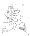
- an emergency power unit 10 comprises a casing I inside which several management and control devices are included, as it will be disclosed in detail below, and a plurality of connecting means arranged to perform continued power supply functions.
- unit 10 comprises, for instance, a first input connector 12 arranged to be connected, through a first input cable 32a, to a first power supply unit 42 for a first device or apparatus 52, for instance an IP (Internet Protocol) telephone set, known per se.
- IP Internet Protocol
- Such a first input connector 12 is associated with a first output connector 22, arranged to be connected to the first device 52 through a first output cable 32b, preferably having the same electromagnetic characteristics as the first input cable 32a.
- unit 10 further comprises a second input connector 14 arranged to be connected, through a second input cable 34a, to a second power supply unit 44 for a second device or apparatus 54, for instance an IP modem, known per se.
- Such a second input connector 14 is associated with a second output connector 24, arranged to be connected to the second device 54 through a second output cable 34b, preferably having the same electromagnetic characteristics as the second input cable 34a.
- the number of mutually associated input and output connectors can be smaller or greater than two, without thereby departing from the scope of the invention as defined by the claims.
- the unit further comprises, according to a first embodiment, a connector 15 arranged to be connected to a mains socket 45, known per se, through an electric cable 35 of known type, for supplying the same unit.
- the unit comprises a further connector arranged to allow supplying, through a further electrical cable, a further emergency power unit having substantially the same characteristics as emergency power unit 10 described herein.
- the connector 15 can be missing and the unit can be supplied or powered by the input connector/connectors 12 and/or 14 respectively, as will be disclosed below in detail.
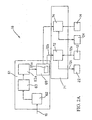
- emergency power unit 10 includes, inside casing 11, an electronic circuit 18 ( Fig. 1 , Fig. 2a , Fig. 2b ).
- Said electronic circuit 18 is arranged, when the mains is operating, to supply domestic devices 52 and/or 54 by using power supply units 42 and 44 and input and output cables 32a and 32b, and/or input and output cables 34a and 34b, respectively, and, in case of a blackout on the mains, to autonomously supply domestic devices 52 and/or 54 by using output cables 32b and 34b, respectively, as disclosed in detail hereinafter.
- circuit 18 comprises a battery charging device 61, of known type, and a supply delivery or supply switching device 71, connected in known manner to the battery charging device and arranged to receive power supply, for instance d.c. power supply, from battery charging device 61 and input connectors 12 and 14.
- power supply for instance d.c. power supply
- Battery charging device 61 that, in use, according to first embodiment ( Fig. 1 , Fig. 2a ) is connected to the mains through electric cable 35, comprises:
- DC/DC converter 65 comprises an electronic circuitry that, when suitably jumped, is capable of supplying output connectors 22 and 24, respectively, for instance with different voltage values with different currents and quality, through supply delivery or switching unit 71.
- microprocessor 65a associates with the output connectors respective voltages and currents, corresponding with those entering through the respective input connectors 12 and 14.
- the voltage and current values can be included into a table stored in microprocessor 65a and suitably selected by the programs developed and stored therein.
- an external control unit can be provided, arranged to configure DC/DC converter 65 at the factory so as to assign, through microprocessor 65a, the voltage and current values envisaged on output connectors 22 and 24, respectively.
- Supply delivery unit 71 preferably comprises one or more than one switching circuits, their number corresponding to the number of output connectors.
- supply delivery unit 71 comprises a first switching circuit 72 and a second switching circuit 74.
- switching circuits 72 and 74 are arranged:
- Both switching circuits 72 and 74 have substantially the same structure so that, for sake of simplicity of the description, only the first of such circuits is described herein, assuming that the second has an identical structure.
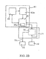
- switching circuit 72 ( Figs. 1 , 2a , 2b and 3 ) has a first input 72a connected to the first input connector 12, a second input 72b connected to an output of DC/DC converter 65, and an output 72c connected to output connector 22.
- switching circuit 72 comprises for instance an electronic circuit 81 and a micro-switch 85 connected in series.
- electronic circuit 81 comprises a detector 82 connected to the first input 72a and capable of detecting a possible blackout or restoration of the mains, and a control logic 84, connected to detector 82 and arranged to receive and handle signals representative of the blackout or the restoration and to consequently control micro-switch 85, as disclosed in detail below.
- control logic 84 comprises a microprocessor logic so programmed that, at the occurrence of a signal representative of a blackout, the logic commands micro-switch 85 to switch the power supply from the first input 72a to the second input 72b connected to DC/DC converter 65.
- said switching operation is performer by switching micro-switch 85 to an open condition so that the switching time is extremely short, e.g. lower than or equal to 500 ⁇ s.
- Control logic 84 is also programmed or configured so that, at the occurrence of a signal representative of the restoration of the power supply from the mains, coming from detector 82, the logic:
- each switching circuit 72 or 74, respectively, and in particular of control logic 84 ensures that each break of the power supply from the mains is handled very quickly, whereas the restoration of the power supply from the mains is controlled so as to prevent instability in the supply of domestic devices.
- the input connector/connectors (12, 14) is (considering one input connector) connected to the switching circuit 72 ( Fig. 2b , Fig. 3 ) and in parallel to the DC/DC converter 65.
- the switching circuit 72 is configured and operates in the same way as already disclosed.
- the DC/DC converter is DC powered from the input connector/connectors 12 and/or 14 and in turn it powers the battery charger 63 for charging the battery stack 63a in the same way as already disclosed in relation with the first embodiment.
- the electrical power received from the DC/DC converter 65 is, in general terms, properly choked by a current limiter, of known type, provided for avoiding overloading and fault of the power supply unit 42 due to power supply overloading.
- Such an embodiment advantageously, allows to avoid the connector cable 15 because the input connector/connectors 12 and/or 14 are arranged to provide power supply to the battery charger 61 through the DC/DC converter 65.
- the various domestic devices 52 and/or 54 are supplied by the respective power supply units 42 and 44 through cables 32a and 32b, and/or 34a and 34b.
- output cables 32b and 34b should conveniently have such electromagnetic characteristics that they do not modify the electromagnetic behaviour of the devices connected thereto.
- such condition is generally obtained by using output cables 32b and 34b with substantially the same length and characteristics as input cables 32a and 34a.
- detector 82 instantaneously detects the voltage drop and signals it to control logic 84, which causes the almost instantaneous switching of micro-switch 85, so as to supply apparatus 52 by means of battery stack 63a.
- a possible short restoration of the mains for instance a restoration with duration shorter than a predetermined time period, is detected by detector 82 but is stopped by control logic 84 that maintains micro-switch 85 switched so that power continues being supplied by battery stack 63a.
- control logic 84 commands the switching of micro-switch 85 so as to supply device 52 by means of power supply unit 42.
- an emergency power unit comprising two input and output power supply connectors; yet, as it can be readily understood by a person skilled in the art, the emergency power unit can comprise a number of input and output connectors varying depending on specific installation requirements.
- the emergency power unit can also comprise one or more LEDs connected, for instance, to the electronic circuit and arranged to signal different operation conditions, such as for instance:
Landscapes
- Business, Economics & Management (AREA)
- Emergency Management (AREA)
- Engineering & Computer Science (AREA)
- Power Engineering (AREA)
- Stand-By Power Supply Arrangements (AREA)
- Charge And Discharge Circuits For Batteries Or The Like (AREA)
Claims (11)
- Unité d'alimentation ininterrompue en courant électrique en situation d'urgence, destinée à des appareils, en particulier à des appareils domestiques, agencée en vue d'être alimentée par un adaptateur de courant alternatif / courant continu (CA/CC) (42, 44) présentant en sortie une certaine valeur de courant continu (CC)à travers des moyens de connexion en CC (12, 14), l'unité comportant :- un dispositif de charge de batterie (61) agencé pour accumuler de l'énergie électrique dans des moyens d'accumulateur (63a) par l'intermédiaire des moyens de connexion en CC (12), ledit dispositif de charge de batterie (61) comprenant des moyens de conversion (65) pouvant être connectés en entrée à une sortie des moyens d'accumulateur (63a) et agencés afin de convertir l'énergie électrique accumulée par lesdits moyens d'accumulateur (63a) en une alimentation en courant ayant une valeur en sortie égale à ladite certaine valeur de CC;- des moyens de connexion de sortie (22, 44) pouvant être connectés à au moins l'un desdits appareils (52, 54) pour l'alimenter avec un bloc d'alimentation ; caractérisée par le fait de- des moyens de commutation de connexion (72, 74) agencés pour commuter , en fonctionnement, la connexion des moyens de connexion de sortie (22, 24) à partir des/vers les moyens de connexion en CC (12) et à partir des/vers lesdits moyens de conversion (65, 65a) afin d'alimenter en courant de façon ininterrompue ledit au moins un desdits appareils (52, 54) en fonction de la coupure ou de la restauration du courant électrique alternatif (CA) pour ledit adaptateur CA/CC (42, 44).
- Unité d'alimentation électrique en cas d'urgence selon la revendication 1 dans laquelle lesdits moyens de connexion en CC (12, 14) sont agencés afin de fournir du courant électrique CC au dit dispositif de charge de batterie (61).
- Unité d'alimentation électrique en cas d'urgence selon la revendication 1 comprenant, de plus, des moyens de connexion en CA (12, 14) (15) agencés en vue de fournir du courant électrique alternatif au dit dispositif de charge de batterie (61).
- Unité d'alimentation électrique en cas d'urgence selon l'une quelconque des revendications 1 à 3, caractérisée en ce que lesdits moyens de conversion comprennent au moins un dispositif de conversion continu/continu (65).
- Unité d'alimentation électrique en cas d'urgence selon l'une quelconque des revendications 1 à 4, caractérisée en ce que lesdits moyens de conversion comportent au moins un circuit (65a) configuré pour alimenter les moyens de commutation (72, 74) avec une pluralité de valeurs de tension et d'intensité de courant selon des paramètres prédéterminés.
- Unité d'alimentation électrique en cas d'urgence selon l'une quelconque des revendications 1 à 5, caractérisée en ce que lesdits moyens de commutation (72) comprennent- au moins un détecteur (82) agencé pour détecter la présence de courant au niveau des moyens de connexion en CC (12, 14) ;- au moins une logique de commande (84) ayant une entrée connectée au détecteur (82) ;- au moins un circuit de commutation (85) commandé par la logique de commande (84) afin de commuter la connexion à partir d'au moins un desdits premiers moyens de connexion (12, 14) vers au moins l'un desdits moyens de conversion (65) et vice versa.
- Unité d'alimentation électrique en cas d'urgence selon la revendication 6, caractérisée en ce que ladite logique de commande comporte des moyens agencés pour entraîner la commutation essentiellement instantanée dudit circuit de commutation desdits premiers moyens de connexion (12, 14) auxdits moyens de conversion (65), et pour entraîner la commutation desdits moyens de conversion (65, 65a) auxdits premiers moyens de connexion (12, 14) avec un temps de retard prédéterminé.
- Procédé pour alimenter en courant, au moyen d'une unité d'alimentation ininterrompue en cas d'urgence, un ou plusieurs appareils, en particulier un ou plusieurs appareils domestiques, agencée pour être alimentée par un adaptateur CA/CC (42, 44) avec une certaine valeur de CC à travers des moyens de connexion en CC (12, 14), le procédé comportant les étapes consistant à :- accumuler de l'énergie électrique provenant de l'alimentation générale par l'intermédiaire des moyens de connexion en CC (12) ;- convertir, à l'aide de moyens de conversion (65, 65a), l'énergie électrique accumulée en une certaine alimentation électrique présentant une valeur en sortie égale à ladite certaine valeur de CC de sorte que ladite alimentation électrique peut être utilisée par ledit appareil ou lesdits plusieurs appareils ;- alimenter ledit ou lesdits appareil(s) avec du courant à l'aide des moyens de connexion de sortie (22, 24) pouvant être connectés au dit un ou auxdits plusieurs appareil(s) à travers ladite unité d'alimentation ininterrompue en courant électrique en cas d'urgence (10);- commuter, en fonctionnement, les moyens de connexion de sortie (22, 24) à partir de /vers les moyens de connexion en CC (12) et à partir des/vers les moyens de conversion (65, 65a) afin d'alimenter de façon ininterrompue en courant électrique ledit un ou lesdits plusieurs appareil(s) en fonction d'une coupure d'une interruption ou d'une restauration du courant électrique alternatif.
- Procédé selon la revendication 8, caractérisé en ce que l'étape de conversion comprend la conversion de l'énergie électrique accumulée CC en ladite certaine alimentation électrique en CC.
- Procédé selon l'une quelconque des revendications 8 à 9, caractérisé en ce que l'étape de commutation comprend les phases de :- détection de la présence de courant au niveau des moyens de connexion en CC (12, 14) ;- commutation essentiellement instantanée de l'alimentation électrique à partir desdits premiers moyens de connexion (12, 14) vers lesdits moyens de conversion (65, 65a) dans le cas où l'absence de courant est détectée au niveau des premiers moyens de connexion (12, 14).
- Procédé selon la revendication 10, caractérisé en ce que ladite étape de commutation comprend la phase supplémentaire de- commutation de la connexion desdits moyens de conversion (65, 65a) aux dits moyens de connexion en CC (12, 14) avec un temps de retard prédéterminé si du courant est détecté au niveau des moyens de connexion en CC (12, 14).
Priority Applications (1)
| Application Number | Priority Date | Filing Date | Title |
|---|---|---|---|
| US12/391,660 US8115338B2 (en) | 2008-02-25 | 2009-02-24 | Emergency power unit |
Applications Claiming Priority (1)
| Application Number | Priority Date | Filing Date | Title |
|---|---|---|---|
| PCT/IT2008/000126 WO2009107150A1 (fr) | 2008-02-25 | 2008-02-25 | Unité d'alimentation électrique sans coupure |
Publications (2)
| Publication Number | Publication Date |
|---|---|
| EP2093859A1 EP2093859A1 (fr) | 2009-08-26 |
| EP2093859B1 true EP2093859B1 (fr) | 2010-09-15 |
Family
ID=39967216
Family Applications (1)
| Application Number | Title | Priority Date | Filing Date |
|---|---|---|---|
| EP20090150194 Not-in-force EP2093859B1 (fr) | 2008-02-25 | 2009-01-08 | Unité d'alimentation en courant continue |
Country Status (7)
| Country | Link |
|---|---|
| US (1) | US8115338B2 (fr) |
| EP (1) | EP2093859B1 (fr) |
| CN (1) | CN101527466A (fr) |
| AT (1) | ATE481767T1 (fr) |
| DE (1) | DE602009000172D1 (fr) |
| ES (1) | ES2353048T3 (fr) |
| WO (1) | WO2009107150A1 (fr) |
Families Citing this family (9)
| Publication number | Priority date | Publication date | Assignee | Title |
|---|---|---|---|---|
| FR2938986B1 (fr) | 2008-11-25 | 2010-12-17 | Bull Sas | Dispositif d'alimentation de secours en courant continu d'un systeme electrique. |
| JP2011083052A (ja) * | 2009-10-02 | 2011-04-21 | Panasonic Electric Works Co Ltd | 負荷制御システム |
| US20120046798A1 (en) * | 2010-08-19 | 2012-02-23 | Heat Assured Systems, Llc | Systems and Methods for Power Demand Management |
| FR2977783B1 (fr) * | 2011-07-13 | 2014-03-14 | Seb Sa | Poignee amovible rechargeable |
| US9735613B2 (en) | 2012-11-19 | 2017-08-15 | Heat Assured Systems, Llc | System and methods for controlling a supply of electric energy |
| JP6241421B2 (ja) * | 2013-01-22 | 2017-12-06 | ソニー株式会社 | 制御装置、制御方法、およびプログラム |
| US10797490B2 (en) * | 2014-03-26 | 2020-10-06 | Intersil Americas LLC | Battery charge system with transition control that protects adapter components when transitioning from battery mode to adapter mode |
| CN106300473A (zh) * | 2015-05-29 | 2017-01-04 | 西安中兴新软件有限责任公司 | 一种接入终端的供电方法及接入终端 |
| IT201700120257A1 (it) * | 2017-10-24 | 2019-04-24 | Newen Srl | Dispositivo di alimentazione elettrica particolarmente per dispositivi di rete di tipo residenziale. |
Family Cites Families (8)
| Publication number | Priority date | Publication date | Assignee | Title |
|---|---|---|---|---|
| JPH10309045A (ja) * | 1997-05-07 | 1998-11-17 | Sony Corp | 予備電源装置 |
| JP2000014043A (ja) * | 1998-06-05 | 2000-01-14 | Internatl Business Mach Corp <Ibm> | 無停電電源装置 |
| JP2000197347A (ja) * | 1998-12-25 | 2000-07-14 | Hitachi Ltd | 電源装置 |
| JP4025216B2 (ja) * | 2003-02-21 | 2007-12-19 | 株式会社日立製作所 | 無停電電源装置 |
| US7294940B2 (en) * | 2005-02-01 | 2007-11-13 | System Engineering International | Power over ethernet battery backup |
| US7709976B2 (en) | 2005-07-19 | 2010-05-04 | Linear Technology Corporation | Dual-input DC-DC converter with integrated ideal diode function |
| JP2007306647A (ja) * | 2006-05-09 | 2007-11-22 | Lenovo Singapore Pte Ltd | 電源システムおよび電子機器 |
| US20080042492A1 (en) * | 2006-08-17 | 2008-02-21 | Gleason Patrick T | Electric power distribution and backup power supply system |
-
2008
- 2008-02-25 WO PCT/IT2008/000126 patent/WO2009107150A1/fr not_active Ceased
-
2009
- 2009-01-08 DE DE200960000172 patent/DE602009000172D1/de active Active
- 2009-01-08 ES ES09150194T patent/ES2353048T3/es active Active
- 2009-01-08 AT AT09150194T patent/ATE481767T1/de not_active IP Right Cessation
- 2009-01-08 EP EP20090150194 patent/EP2093859B1/fr not_active Not-in-force
- 2009-02-24 US US12/391,660 patent/US8115338B2/en not_active Expired - Fee Related
- 2009-02-25 CN CNA2009101182167A patent/CN101527466A/zh active Pending
Also Published As
| Publication number | Publication date |
|---|---|
| ES2353048T3 (es) | 2011-02-24 |
| ATE481767T1 (de) | 2010-10-15 |
| US20090212632A1 (en) | 2009-08-27 |
| US8115338B2 (en) | 2012-02-14 |
| EP2093859A1 (fr) | 2009-08-26 |
| CN101527466A (zh) | 2009-09-09 |
| WO2009107150A1 (fr) | 2009-09-03 |
| DE602009000172D1 (de) | 2010-10-28 |
Similar Documents
| Publication | Publication Date | Title |
|---|---|---|
| EP2093859B1 (fr) | Unité d'alimentation en courant continue | |
| AU2013201985B2 (en) | Power module system | |
| EP3190682B1 (fr) | Système et procédé d'alimentation électrique | |
| RU2506680C2 (ru) | Устройство, система и способ источника бесперебойного питания | |
| EP3210270B1 (fr) | Système de récepteur d'énergie numérique | |
| US9124101B2 (en) | Power supply having selectable operation based on communications with load | |
| US20040189251A1 (en) | Modular and reconfigurable rapid battery charger | |
| CN114982200B (zh) | 用于电力分配的系统、方法、及装置 | |
| CN211266789U (zh) | 一种新型拓扑结构的多端口适配器 | |
| CN104953879A (zh) | 一种三相逆变器的单相紧急工作方式以及相应的逆变器 | |
| JP6194262B2 (ja) | 直流給電装置、及び給電制御方法 | |
| JP7311564B2 (ja) | インテリジェントスイッチ装置及び発電システム | |
| WO2009076662A1 (fr) | Système de conservation d'énergie électrique | |
| CN107370168B (zh) | 电能存储设备 | |
| WO2016078353A1 (fr) | Circuit de bus d'alimentation électrique | |
| CN108075561A (zh) | 可自动切换电源的电源分配单元 | |
| CN110138404A (zh) | 用于向保护和控制设备提供无线连接的收发器设备 | |
| CN108429333B (zh) | 配电装置及其操作方法 | |
| CN213782964U (zh) | 智能控制直流输出的不断电装置 | |
| WO2013147489A1 (fr) | Chargeur pour bloquer l'énergie fantôme et procédé de commande associé | |
| CN108631433B (zh) | 一种数据机房柜间能量调度管理系统及方法 | |
| CN112703656A (zh) | 供电装置以及供电系统 | |
| CN106787644B (zh) | 电源管理系统及其电力供应方法 | |
| US9583974B1 (en) | Uninterruptible power supply for an electric apparatus | |
| US20200301493A1 (en) | Photovoltaic system and inverter having a communication interface |
Legal Events
| Date | Code | Title | Description |
|---|---|---|---|
| PUAI | Public reference made under article 153(3) epc to a published international application that has entered the european phase |
Free format text: ORIGINAL CODE: 0009012 |
|
| 17P | Request for examination filed |
Effective date: 20090528 |
|
| AK | Designated contracting states |
Kind code of ref document: A1 Designated state(s): AT BE BG CH CY CZ DE DK EE ES FI FR GB GR HR HU IE IS IT LI LT LU LV MC MK MT NL NO PL PT RO SE SI SK TR |
|
| AX | Request for extension of the european patent |
Extension state: AL BA RS |
|
| 17Q | First examination report despatched |
Effective date: 20090924 |
|
| AKX | Designation fees paid | ||
| GRAP | Despatch of communication of intention to grant a patent |
Free format text: ORIGINAL CODE: EPIDOSNIGR1 |
|
| RBV | Designated contracting states (corrected) |
Designated state(s): AT BE BG CH CY CZ DE DK EE ES FI FR GB GR HR HU IE IS IT LI LT LU LV MC MK MT NL NO PL PT RO SE SI SK TR |
|
| REG | Reference to a national code |
Ref country code: DE Ref legal event code: 8566 |
|
| GRAS | Grant fee paid |
Free format text: ORIGINAL CODE: EPIDOSNIGR3 |
|
| GRAA | (expected) grant |
Free format text: ORIGINAL CODE: 0009210 |
|
| AK | Designated contracting states |
Kind code of ref document: B1 Designated state(s): AT BE BG CH CY CZ DE DK EE ES FI FR GB GR HR HU IE IS IT LI LT LU LV MC MK MT NL NO PL PT RO SE SI SK TR |
|
| REG | Reference to a national code |
Ref country code: GB Ref legal event code: FG4D Ref country code: CH Ref legal event code: EP |
|
| REG | Reference to a national code |
Ref country code: IE Ref legal event code: FG4D |
|
| REF | Corresponds to: |
Ref document number: 602009000172 Country of ref document: DE Date of ref document: 20101028 Kind code of ref document: P |
|
| REG | Reference to a national code |
Ref country code: NL Ref legal event code: VDEP Effective date: 20100915 |
|
| PG25 | Lapsed in a contracting state [announced via postgrant information from national office to epo] |
Ref country code: AT Free format text: LAPSE BECAUSE OF FAILURE TO SUBMIT A TRANSLATION OF THE DESCRIPTION OR TO PAY THE FEE WITHIN THE PRESCRIBED TIME-LIMIT Effective date: 20100915 Ref country code: FI Free format text: LAPSE BECAUSE OF FAILURE TO SUBMIT A TRANSLATION OF THE DESCRIPTION OR TO PAY THE FEE WITHIN THE PRESCRIBED TIME-LIMIT Effective date: 20100915 Ref country code: LT Free format text: LAPSE BECAUSE OF FAILURE TO SUBMIT A TRANSLATION OF THE DESCRIPTION OR TO PAY THE FEE WITHIN THE PRESCRIBED TIME-LIMIT Effective date: 20100915 Ref country code: NO Free format text: LAPSE BECAUSE OF FAILURE TO SUBMIT A TRANSLATION OF THE DESCRIPTION OR TO PAY THE FEE WITHIN THE PRESCRIBED TIME-LIMIT Effective date: 20101215 |
|
| REG | Reference to a national code |
Ref country code: ES Ref legal event code: FG2A Effective date: 20110214 |
|
| LTIE | Lt: invalidation of european patent or patent extension |
Effective date: 20100915 |
|
| PG25 | Lapsed in a contracting state [announced via postgrant information from national office to epo] |
Ref country code: HR Free format text: LAPSE BECAUSE OF FAILURE TO SUBMIT A TRANSLATION OF THE DESCRIPTION OR TO PAY THE FEE WITHIN THE PRESCRIBED TIME-LIMIT Effective date: 20100915 Ref country code: SI Free format text: LAPSE BECAUSE OF FAILURE TO SUBMIT A TRANSLATION OF THE DESCRIPTION OR TO PAY THE FEE WITHIN THE PRESCRIBED TIME-LIMIT Effective date: 20100915 Ref country code: PL Free format text: LAPSE BECAUSE OF FAILURE TO SUBMIT A TRANSLATION OF THE DESCRIPTION OR TO PAY THE FEE WITHIN THE PRESCRIBED TIME-LIMIT Effective date: 20100915 Ref country code: CY Free format text: LAPSE BECAUSE OF FAILURE TO SUBMIT A TRANSLATION OF THE DESCRIPTION OR TO PAY THE FEE WITHIN THE PRESCRIBED TIME-LIMIT Effective date: 20100915 |
|
| PG25 | Lapsed in a contracting state [announced via postgrant information from national office to epo] |
Ref country code: GR Free format text: LAPSE BECAUSE OF FAILURE TO SUBMIT A TRANSLATION OF THE DESCRIPTION OR TO PAY THE FEE WITHIN THE PRESCRIBED TIME-LIMIT Effective date: 20101216 Ref country code: SE Free format text: LAPSE BECAUSE OF FAILURE TO SUBMIT A TRANSLATION OF THE DESCRIPTION OR TO PAY THE FEE WITHIN THE PRESCRIBED TIME-LIMIT Effective date: 20100915 Ref country code: LV Free format text: LAPSE BECAUSE OF FAILURE TO SUBMIT A TRANSLATION OF THE DESCRIPTION OR TO PAY THE FEE WITHIN THE PRESCRIBED TIME-LIMIT Effective date: 20100915 |
|
| PG25 | Lapsed in a contracting state [announced via postgrant information from national office to epo] |
Ref country code: EE Free format text: LAPSE BECAUSE OF FAILURE TO SUBMIT A TRANSLATION OF THE DESCRIPTION OR TO PAY THE FEE WITHIN THE PRESCRIBED TIME-LIMIT Effective date: 20100915 Ref country code: RO Free format text: LAPSE BECAUSE OF FAILURE TO SUBMIT A TRANSLATION OF THE DESCRIPTION OR TO PAY THE FEE WITHIN THE PRESCRIBED TIME-LIMIT Effective date: 20100915 Ref country code: CZ Free format text: LAPSE BECAUSE OF FAILURE TO SUBMIT A TRANSLATION OF THE DESCRIPTION OR TO PAY THE FEE WITHIN THE PRESCRIBED TIME-LIMIT Effective date: 20100915 Ref country code: PT Free format text: LAPSE BECAUSE OF FAILURE TO SUBMIT A TRANSLATION OF THE DESCRIPTION OR TO PAY THE FEE WITHIN THE PRESCRIBED TIME-LIMIT Effective date: 20110117 Ref country code: IS Free format text: LAPSE BECAUSE OF FAILURE TO SUBMIT A TRANSLATION OF THE DESCRIPTION OR TO PAY THE FEE WITHIN THE PRESCRIBED TIME-LIMIT Effective date: 20110115 Ref country code: NL Free format text: LAPSE BECAUSE OF FAILURE TO SUBMIT A TRANSLATION OF THE DESCRIPTION OR TO PAY THE FEE WITHIN THE PRESCRIBED TIME-LIMIT Effective date: 20100915 Ref country code: SK Free format text: LAPSE BECAUSE OF FAILURE TO SUBMIT A TRANSLATION OF THE DESCRIPTION OR TO PAY THE FEE WITHIN THE PRESCRIBED TIME-LIMIT Effective date: 20100915 |
|
| PG25 | Lapsed in a contracting state [announced via postgrant information from national office to epo] |
Ref country code: BE Free format text: LAPSE BECAUSE OF FAILURE TO SUBMIT A TRANSLATION OF THE DESCRIPTION OR TO PAY THE FEE WITHIN THE PRESCRIBED TIME-LIMIT Effective date: 20100915 |
|
| PLBE | No opposition filed within time limit |
Free format text: ORIGINAL CODE: 0009261 |
|
| STAA | Information on the status of an ep patent application or granted ep patent |
Free format text: STATUS: NO OPPOSITION FILED WITHIN TIME LIMIT |
|
| 26N | No opposition filed |
Effective date: 20110616 |
|
| PG25 | Lapsed in a contracting state [announced via postgrant information from national office to epo] |
Ref country code: MC Free format text: LAPSE BECAUSE OF NON-PAYMENT OF DUE FEES Effective date: 20110131 Ref country code: DK Free format text: LAPSE BECAUSE OF FAILURE TO SUBMIT A TRANSLATION OF THE DESCRIPTION OR TO PAY THE FEE WITHIN THE PRESCRIBED TIME-LIMIT Effective date: 20100915 |
|
| REG | Reference to a national code |
Ref country code: DE Ref legal event code: R097 Ref document number: 602009000172 Country of ref document: DE Effective date: 20110616 |
|
| REG | Reference to a national code |
Ref country code: IE Ref legal event code: MM4A |
|
| PG25 | Lapsed in a contracting state [announced via postgrant information from national office to epo] |
Ref country code: MT Free format text: LAPSE BECAUSE OF FAILURE TO SUBMIT A TRANSLATION OF THE DESCRIPTION OR TO PAY THE FEE WITHIN THE PRESCRIBED TIME-LIMIT Effective date: 20100915 |
|
| PG25 | Lapsed in a contracting state [announced via postgrant information from national office to epo] |
Ref country code: IE Free format text: LAPSE BECAUSE OF NON-PAYMENT OF DUE FEES Effective date: 20110108 |
|
| PGFP | Annual fee paid to national office [announced via postgrant information from national office to epo] |
Ref country code: FR Payment date: 20120104 Year of fee payment: 4 Ref country code: ES Payment date: 20111229 Year of fee payment: 4 |
|
| PGFP | Annual fee paid to national office [announced via postgrant information from national office to epo] |
Ref country code: IT Payment date: 20120131 Year of fee payment: 4 |
|
| PGFP | Annual fee paid to national office [announced via postgrant information from national office to epo] |
Ref country code: DE Payment date: 20120326 Year of fee payment: 4 |
|
| PG25 | Lapsed in a contracting state [announced via postgrant information from national office to epo] |
Ref country code: MK Free format text: LAPSE BECAUSE OF FAILURE TO SUBMIT A TRANSLATION OF THE DESCRIPTION OR TO PAY THE FEE WITHIN THE PRESCRIBED TIME-LIMIT Effective date: 20100915 |
|
| PG25 | Lapsed in a contracting state [announced via postgrant information from national office to epo] |
Ref country code: LU Free format text: LAPSE BECAUSE OF NON-PAYMENT OF DUE FEES Effective date: 20110108 |
|
| REG | Reference to a national code |
Ref country code: CH Ref legal event code: PL |
|
| GBPC | Gb: european patent ceased through non-payment of renewal fee |
Effective date: 20130108 |
|
| PG25 | Lapsed in a contracting state [announced via postgrant information from national office to epo] |
Ref country code: TR Free format text: LAPSE BECAUSE OF FAILURE TO SUBMIT A TRANSLATION OF THE DESCRIPTION OR TO PAY THE FEE WITHIN THE PRESCRIBED TIME-LIMIT Effective date: 20100915 Ref country code: BG Free format text: LAPSE BECAUSE OF FAILURE TO SUBMIT A TRANSLATION OF THE DESCRIPTION OR TO PAY THE FEE WITHIN THE PRESCRIBED TIME-LIMIT Effective date: 20101215 |
|
| REG | Reference to a national code |
Ref country code: FR Ref legal event code: ST Effective date: 20130930 |
|
| PG25 | Lapsed in a contracting state [announced via postgrant information from national office to epo] |
Ref country code: HU Free format text: LAPSE BECAUSE OF FAILURE TO SUBMIT A TRANSLATION OF THE DESCRIPTION OR TO PAY THE FEE WITHIN THE PRESCRIBED TIME-LIMIT Effective date: 20100915 Ref country code: DE Free format text: LAPSE BECAUSE OF NON-PAYMENT OF DUE FEES Effective date: 20130801 Ref country code: LI Free format text: LAPSE BECAUSE OF NON-PAYMENT OF DUE FEES Effective date: 20130131 Ref country code: CH Free format text: LAPSE BECAUSE OF NON-PAYMENT OF DUE FEES Effective date: 20130131 |
|
| REG | Reference to a national code |
Ref country code: DE Ref legal event code: R119 Ref document number: 602009000172 Country of ref document: DE Effective date: 20130801 |
|
| PG25 | Lapsed in a contracting state [announced via postgrant information from national office to epo] |
Ref country code: GB Free format text: LAPSE BECAUSE OF NON-PAYMENT OF DUE FEES Effective date: 20130108 Ref country code: FR Free format text: LAPSE BECAUSE OF NON-PAYMENT OF DUE FEES Effective date: 20130131 |
|
| PG25 | Lapsed in a contracting state [announced via postgrant information from national office to epo] |
Ref country code: IT Free format text: LAPSE BECAUSE OF NON-PAYMENT OF DUE FEES Effective date: 20130108 |
|
| REG | Reference to a national code |
Ref country code: ES Ref legal event code: FD2A Effective date: 20140321 |
|
| PG25 | Lapsed in a contracting state [announced via postgrant information from national office to epo] |
Ref country code: ES Free format text: LAPSE BECAUSE OF NON-PAYMENT OF DUE FEES Effective date: 20130109 |