EP2093899B1 - Station mobile et procédé de contrôle de vérification d'antenne sur une station mobile - Google Patents
Station mobile et procédé de contrôle de vérification d'antenne sur une station mobile Download PDFInfo
- Publication number
- EP2093899B1 EP2093899B1 EP06834824.2A EP06834824A EP2093899B1 EP 2093899 B1 EP2093899 B1 EP 2093899B1 EP 06834824 A EP06834824 A EP 06834824A EP 2093899 B1 EP2093899 B1 EP 2093899B1
- Authority
- EP
- European Patent Office
- Prior art keywords
- section
- antenna
- dpch
- transmission
- base station
- Prior art date
- Legal status (The legal status is an assumption and is not a legal conclusion. Google has not performed a legal analysis and makes no representation as to the accuracy of the status listed.)
- Not-in-force
Links
Images


Classifications
-
- H—ELECTRICITY
- H04—ELECTRIC COMMUNICATION TECHNIQUE
- H04B—TRANSMISSION
- H04B7/00—Radio transmission systems, i.e. using radiation field
- H04B7/02—Diversity systems; Multi-antenna system, i.e. transmission or reception using multiple antennas
- H04B7/04—Diversity systems; Multi-antenna system, i.e. transmission or reception using multiple antennas using two or more spaced independent antennas
- H04B7/06—Diversity systems; Multi-antenna system, i.e. transmission or reception using multiple antennas using two or more spaced independent antennas at the transmitting station
- H04B7/0613—Diversity systems; Multi-antenna system, i.e. transmission or reception using multiple antennas using two or more spaced independent antennas at the transmitting station using simultaneous transmission
- H04B7/0615—Diversity systems; Multi-antenna system, i.e. transmission or reception using multiple antennas using two or more spaced independent antennas at the transmitting station using simultaneous transmission of weighted versions of same signal
- H04B7/0619—Diversity systems; Multi-antenna system, i.e. transmission or reception using multiple antennas using two or more spaced independent antennas at the transmitting station using simultaneous transmission of weighted versions of same signal using feedback from receiving side
- H04B7/0652—Feedback error handling
- H04B7/0654—Feedback error handling at the receiver, e.g. antenna verification at mobile station
-
- H—ELECTRICITY
- H04—ELECTRIC COMMUNICATION TECHNIQUE
- H04B—TRANSMISSION
- H04B7/00—Radio transmission systems, i.e. using radiation field
- H04B7/02—Diversity systems; Multi-antenna system, i.e. transmission or reception using multiple antennas
- H04B7/04—Diversity systems; Multi-antenna system, i.e. transmission or reception using multiple antennas using two or more spaced independent antennas
- H04B7/06—Diversity systems; Multi-antenna system, i.e. transmission or reception using multiple antennas using two or more spaced independent antennas at the transmitting station
- H04B7/0613—Diversity systems; Multi-antenna system, i.e. transmission or reception using multiple antennas using two or more spaced independent antennas at the transmitting station using simultaneous transmission
- H04B7/0615—Diversity systems; Multi-antenna system, i.e. transmission or reception using multiple antennas using two or more spaced independent antennas at the transmitting station using simultaneous transmission of weighted versions of same signal
- H04B7/0619—Diversity systems; Multi-antenna system, i.e. transmission or reception using multiple antennas using two or more spaced independent antennas at the transmitting station using simultaneous transmission of weighted versions of same signal using feedback from receiving side
Definitions
- the present invention relates to a mobile station and an antenna verification controlling method for the mobile station, and particularly to a technique suitable for use, for example, with antenna verification control when transmission diversity of a mobile station is applied upon HSDPA (High Speed Downlink Packet Access) operation of a W-CDMA wireless communication system.
- HSDPA High Speed Downlink Packet Access
- phase controlling information transmission antenna weight
- FBI Field Indicator
- the wireless terminal carries out, using a pilot symbol of a dedicated physical channel (DPCH: Dedicated Physical CHannel) of the downlink, antenna verification for estimating the transmission antenna weight (transmission carrier phase) in each slot of the DPCH.
- DPCH dedicated Physical CHannel
- TPC transmission power control
- antenna verification of an HS-PDSCH that is a shared channel of the downlink can be applied and carried out using a dedicated pilot symbol of an associated dedicated physical channel (Associated Dedicated Physical Channel: A-DPCH) of the downlink (for example, refer to Patent Document 1).
- HS-PDSCH High Speed Physical Downlink Shared Channel
- A-DPCH Associated Dedicated Physical Channel
- the antenna verification of the HS-PDSCH is controlled with the dedicated pilot symbol of the A-DPCH, then the power of the A-DPCH is generally very low in comparison with that of the HS-PDSCH. Therefore, the error ratio of the FBI bit increases rather than the degradation ratio of the quality of the HS-PDSCH and the throughput characteristic degrades on the contrary because of the antenna verification.
- the control of the antenna verification is not used during the HSDPA (a result of estimation of signal phases from two transmission antennas is not reflected).
- Patent Document 1 Japanese Laid-open Patent Publication No. 2006-222937 (also published EP1681784A2 ) refers to a mobile station apparatus communicating with a wireless base station apparatus to which closed-loop transmission diversity control is applied, the closed-loop transmission diversity control controlling phases of signals transmitted from two antennas based upon feedback information notified by the mobile station apparatus and transmitting the signals.
- the mobile station apparatus includes a control unit which determines whether to reflect an estimated phase result of the signals transmitted from the two antennas or not, depending on a channel type of signals transmitted from the wireless base station apparatus.
- US2006183439 A1 refers to methods and systems for diversity processing including using dedicated pilot method for closed loop including combining a plurality of received WCDMA/HSDPA multipath signals for each diversity transmit antenna to at least one processed diversity signal.
- the received WCDMA/HSDPA multipath signals may originate from diversity transmit antennas at a base station that may be transmitting information via a closed loop or open loop diversity transmission mode.
- the closed loop diversity transmission mode maybe closed loop 1 or closed loop 2.
- Estimations may be made of the closed loop transmit weights used by the base station for transmission of the symbols. Closed loop symbols transmitted by the diversity transmit antennas may then be estimated based on received diversity signals and at least one dedicated pilot channel. Open loop symbols may be estimated using information from at least one common pilot channel.
- the A-DPCH and the HS-PDSCH of the downlink are started (opened), that is, where reception is started, at the same time in a bearer service of a wireless terminal or the like, there is a state (period) wherein actually the FBI bit does not reach the wireless base station within several frames from transmission starting of a DPCCH (Dedicated Physical Control Channel) that is the dedicated physical channel (DPCH) for controlling information of the uplink before establishment of synchronism of the uplink.
- a DPCCH Dedicated Physical Control Channel
- DPCH dedicated physical channel
- the wireless base station carries out transmission in the downlink in a state wherein the phase is fixed to an initial phase and the wireless terminal carries out the antenna verification, then it cannot be avoided to carry out the antenna verification based only on another FBI bit transmitted in the past (in particular, using the FBI as an initial value) within a period wherein the A-DPCH and the HS-PDSCH are not received.
- TPC command transmission power controlling information
- the present invention has been made in view of such a subj ect as described above, and it is an object of the present invention to reduce the ratio of failure in synchronism establishment that is caused by controlling the antenna verification of transmission diversity, which is carried out for enhancement of the reception characteristic of the downlink, in the OFF state in order to enhance the throughput characteristic as in a case wherein HSDPA is applied.
- the present invention is characterized in that it uses a mobile station and an antenna verification controlling method described below.
- the antenna verification is controlled in the ON state until synchronism of the uplink is established so that a correct phase difference between the CPICH #1 and the CPICH #2 can be detected without referring to an FBI bit history. Further, since, even if feedback information to the wireless base station does not reach the wireless base station and therefore the signal phases from the two antennas are fixed, the antenna verification operates (a result of estimation is reflected on the reception signal process), an opposite phase state of specific channels (for example, a shared pilot channel and a dedicated physical channel) of the downlink can be cancelled. Accordingly, the probability that transmission power controlling information of the downlink may be mistaken can be decreased and the probability that synchronism establishment of the uplink may result in success can be increased.
- specific channels for example, a shared pilot channel and a dedicated physical channel
- BS wireless base station
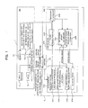
- FIG. 1 is a block diagram illustrating a configuration of essential part of a wireless communication system for explaining antenna verification operation in transmission diversity according to a first embodiment of the present invention.
- the wireless communication system illustrated in FIG. 1 includes a wireless base station (BS) 1 and a wireless terminal (mobile station: MS) 2 for carrying out wireless communication with the BS 1 within a wireless area formed by the BS 1.
- the BS 1 includes, for example, as a transmission system, two antennas (#1 and #2) 10-1 and 10-2, a dedicated physical channel (DPCH) and shared channel (HS-PDSCH) processing section 11, a shared pilot channel (CPICH) processing section 12 and a weight (weighting) setting section 13.
- DPCH dedicated physical channel
- HS-PDSCH shared channel
- CPICH shared pilot channel
- the DPCH ⁇ HS-PDSCH processing section 11 produces a signal of dedicated physical channels (DPCH and HS-PDSCH) of the downlink to be transmitted to the MS 2 and the CPICH processing section 12 produces a signal (known signal between the BS 1 and the MS 2) of a CPICH, which is a pilot channel commonly used for a plurality of MSs 2, and the signals of the channels are transmitted from the antennas 10-1 and 10-2 toward the MS 2.
- DPCH and HS-PDSCH processing section 11 produces a signal of dedicated physical channels (DPCH and HS-PDSCH) of the downlink to be transmitted to the MS 2
- the CPICH processing section 12 produces a signal (known signal between the BS 1 and the MS 2) of a CPICH, which is a pilot channel commonly used for a plurality of MSs 2, and the signals of the channels are transmitted from the antennas 10-1 and 10-2 toward the MS 2.
- the CPICH and a combination of the DPCH and the HS-PDSCH transmitted from the antenna 10-1 are represented by CPICH #1 and DPCH #1, respectively
- the CPICH and a combination of the DPCH and the HS-PDSCH transmitted from the antenna 10-2 are represented by CPICH #2 and DPCH #2, respectively.
- the weight (weighting) setting section 13 adaptively controls the phase (carrier phase) relationship between the signals (DPCHs #1 and #2) transmitted from the two antennas 10-1 and 10-2 based on feedback information (FBI bit) received with the dedicated physical channel (DPCH) of the uplink from the MS 2, and, in an example illustrated in FIG. 1 , the weight setting section 13 multiplies the signal (DPCH #2) transmitted from the antenna 10-2 by a weight coefficient (antenna weight) corresponding to the FBI, in more detail, a weight coefficient for canceling the phase difference between the antennas 10-1 and 10-2 (between CPICH #1 and CPICH #2) on the MS 2 side to control the phase relationship between the DPCHs #1 and #2 transmitted from the two antennas 10-1 and 10-2. It is to be noted that the weight coefficient is multiplied to the CPICH #2 so as to be reflected on the CPICH #1 with 1-slot delay or 2-slot delay.
- the MS 2 includes an antenna 20, a synchronism detection section 23a for carrying out synchronism detection of the signals (CPICH, DPCH, HS-PDSCH) received by the antenna 20 to decode reception DPCH and HS-PDSCH and an antenna verification section 23b for executing the antenna verification (including production of the FBI bit and transmission antenna weight estimation) by cooperation with the synchronism detection section 23a.
- the antenna verification section 23b can be configured as firmware installed in a DSP (Digital Signal Processor) or the like.
- the synchronism detection section 23a has functions as a CPICH #1-CPICH #2 phase difference detection section 231, a CPICH #2-DPCH (HS-PDSCH) #2 phase difference detection section 232, an SIR measurement /TPC detection/ SW detection section 233 and a DPCH ⁇ HS-PDSCH demodulation section 234, and the antenna verification section 23b has functions as an FBI bit production section 235, an FBI bit history storage section 236, an SIR antenna weight estimation section 237 and a DPCH ⁇ HS-PDSCH antenna weight estimation section 238.
- the CPICH #1 - CPICH #2 phase difference detection section 231 detects a carrier phase difference between the pilot channels (CPICH #1 and CPICH #2) received by the antenna 20 and the CPICH #2 - DPCH (HS-PDSCH) #2 phase difference detection section 232 detects a carrier phase difference between the pilot channel (CPICH #2) and dedicated physical channel (DPCH #2) received by the antenna 20.
- the SIR measurement/TPC detection/SW detection section 233 carries out measurement of the reception SIR (Signal to Interference Ratio), detection of a TPC (Transmission Power Control) bit and detection of a synchronizing word (SW) for the signals received by the antenna 20 based on an antenna weight estimated by the SIR antenna weight estimation section 237 hereinafter described, and the DPCH ⁇ HS-PDSCH demodulation section 234 demodulates the DPCHs and the HS-PDSCHs received by the antenna 20 based on an antenna weight estimated by the DPCH ⁇ HS-PDSCH antenna weight estimation section 238 hereinafter described.
- SIR Signal to Interference Ratio
- TPC Transmission Power Control
- SW synchronizing word
- the detection section 233 and the DPCH ⁇ HS-PDSCH demodulation section 234 individually implement a function as a reception signal processing section for performing the process for the reception signals from the BS 1 based on results of estimation by the estimation sections 237 and 238.
- the reception signal process in the present embodiment is a concept including the processes of the measurement of the reception SIR, detection of the TPC bit, detection of the synchronizing word (SW) and demodulation of the DPCH and the HS-PDSCH.
- the FBI bit production section 235 produces, as the phase controlling information, information relating to a phase rotation amount for minimizing (ideally to zero) the phase difference detected by the CPICH #1 - CPICH #2 phase difference detection section 231 and transmits the produced information as the FBI bit to the BS 1 in the DPCH of the uplink and the FBI bit history storage section 236 stores history information of the FBI bit transmitted to the BS 1 therein.
- the SIR antenna weight estimation section (estimation means) 237 calculates (estimates) the antenna weight to be used for the reception SIR detection by the SIR measurement/TPC detection/SW detection section 233 based on the carrier phase difference detected by the CPICH #2 - DPCH (HS-PDSCH) #2 phase difference detection section 232 and the history of the FBI bit stored in the FBI bit history storage section 236 and the DPCH ⁇ HS-PDSCH antenna weight estimation section (estimation means) 238 calculates (estimates) the antenna weight to be used for the demodulation process by the DPCH ⁇ HS-PDSCH demodulation section 234 based on the carrier phase difference detected by the CPICH #2 - DPCH (HS-PDSCH) #2 phase difference detection section 232 and the history of the FBI bit stored in the FBI bit history storage section 236, and the former estimation result is fed back to the SIR measurement/TPC detection/SW detection section 233 and the latter estimation result is fed back to the DPCH ⁇ HS-PDSCH demodulation section 234.
- the antenna weight estimation sections 237 and 238 estimate, based on the carrier phase difference between the pilot channels in the current reception slot and the FBI bit history in the past, the antenna weights, which the BS 1 sets to data of the current reception slot, and feed back the estimation result to the synchronism detection section 23b (SIRmeasurement/TPC detection/SW detection section 233, DPCH ⁇ HS-PDSCH demodulation section 234) so that the reception SIR measurement and the demodulation of the DPCH and the HS-PDSCH are carried out.
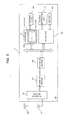
- the MS 2 includes an antenna 20, a W-CDMA wireless frequency (RF) section 21, a W-CDMA analog front end (AFE) section 22, a W-CDMA baseband (BB) section 23, a baseband (BB) CPU 24, an application (APL) section 25, an external interface (IF) 26 for allowing connection to an external equipment, a sound inputting and outputting section 27 such as a speaker, a microphone or the like and a display section 28 such as a liquid crystal display (LCD) or the like, and the synchronism detection section 23a and the antenna verification section 23b described above are provided individually as a function of the W-CDMA baseband section 23.
- RF wireless frequency
- AFE analog front end
- BB baseband
- BB baseband
- BB baseband
- IF external interface
- IF external interface
- the synchronism detection section 23a and the antenna verification section 23b described above are provided individually as a function of the W-CDMA baseband section 23.
- the RF section 21 carries out a required reception RF process including amplification by a low-noise amplifier, frequency conversion (down convert) into an intermediate frequency (IF) band and so forth for a signal of the wireless frequency (RF) received by the antenna 20 and carries out a required transmission RF process including frequency conversion (up convert) into an RF band, amplification by a high-output amplifier and so forth for a transmission signal from the AFE section 22.
- a required reception RF process including amplification by a low-noise amplifier, frequency conversion (down convert) into an intermediate frequency (IF) band and so forth for a signal of the wireless frequency (RF) received by the antenna 20 and carries out a required transmission RF process including frequency conversion (up convert) into an RF band, amplification by a high-output amplifier and so forth for a transmission signal from the AFE section 22.
- the AFE section 22 carries out a required preprocess of the demodulation process including an amplification process, a band limitation process, frequency conversion (down convert) into a baseband frequency and so forth for a reception IF signal from the RF section 21 and carries out a required preprocess including frequency conversion (up convert) into the IF, a band limitation process, an amplification process and so forth for a transmission BB signal from the baseband section 23.
- the BB section 23 carries out a required reception digital BB signal process including synchronism detection using the reception pilot signal, AD conversion for a digital signal process, a back diffusion process, multi-value orthogonal demodulation such as QPSK, 16QAM or the like, error correction decoding (for example, convolution decoding or turbo decoding) and so forth for the reception signal processed by the AFE section 22 under the control of the BB CPU 24 and carries out a required transmission digital BB signal process including error correction coding (for example, convolution coding or turbo coding), a diffusion process, multi-value orthogonal modulation such as QPSK, 16QAM or the like, DA conversion and so forth for the transmission signal (controlling data or application data) from the CPU 24 or the application section 25. Then, as described above, in the BB section 23, production and transmission of the FBI bit and the antenna verification process are carried out by the synchronism detection section 23a and the antenna verification section 23b.
- the BB CPU 24 controls the operation of the BB section 23 (synchronism detection section 23a and antenna verification section 23b) and the applicationsection25processesand executesapplications other than the BB signal process, and the BB CPU 24 and the application section 25 are connected for mutual communication with the BB section 23 through a bus or the like.
- the CPU (monitoring means, controlling means) 24 in the present embodiment has a function as an antenna verification controlling section 24a (refer to FIG. 2 ) for monitoring the communication state (phase) of the uplink to control the ON/OFF state of the antenna verification by the antenna verification section 23b in response to the communication state of the uplink as a result of the monitoring.
- the antenna verification controlling section 24a has functions as an uplink synchronism establishment monitoring function section 241 for monitoring whether or not synchronism of the uplink is established and a first controlling section 242 for controlling the antenna verification by the antenna verification section 23b in the ON state before establishment of the synchronism of the uplink is detected by the monitoring function section 241 but for controlling the antenna verification in the OFF state after establishment of synchronism of the uplink is detected.
- control in the ON state is implemented by feeding back (reflecting) the estimation results by the antenna weight estimation sections 237 and 238 to (on) the synchronism detection section 23a [SIRmeasurement/TPC detection/SW detection section 233 and DPCH ⁇ HS-PDSCH demodulation section 234] and the control in the OFF state is implemented not by feeding back (reflecting) the estimation results.
- the antenna verification controlling section 24a may be provided in the BB section 23 or the function as the controlling section 24a may be separately provided in the CPU 24 and the BB section 23.
- the phase difference detection sections 231 and 232 of the synchronism detection section 23 detect a carrier phase difference for 2 slots between the CPICH #2 and the DPCH #2 transmitted from the two transmission antennas of the BS 1 for the antenna weight set in the 1-slot delay and the antenna weight set in the 2-slot delay in the BS 1 (step S1) and synthesize the carrier phase differences for two slots to acquire an averaged synthesized phase difference (step S2).
- the synthesized phase difference is sent to the SIR antenna weight estimation section 237 of the antenna verification section 23b, and the SIR antenna weight estimation section 237 calculates the antenna weight (phase rotation amount ROTATE) set in the 1-slot delay and the antenna weight set in the 2-slot delay based on the FBI bit in the past stored in the FBI bit history storage section 236 (step S3).
- the SIR antenna weight estimation section 237 feeds back the antenna weights (phase rotation amounts ROTATE) for 2 slots to the SIRmeasurement/TPC detection/SW detection section 233 to set (reflect) the phase rotation amounts of the CPICH #2 for SIR measurement, TPC detection and SW detection (steps S4, S5, S6). Consequently, the SIR measurement/TPC detection/SW detection section 233 thereafter carries out SIR measurement, TPC detection and SW detection with reference to the set phase rotation amounts (antenna weights) of the CPICH #2.
- the antenna weight for the DPCH is estimated by the DPCH ⁇ HS-PDSCH antenna weight estimation section 238 similarly to the CPICH #2 and a result of the estimation is fed back and set to and reflected on the DPCH ⁇ HS-PDSCH demodulation section 234, and the DPCH ⁇ HS-PDSCH demodulation section 234 thereafter carries out the demodulation process of the DPCH and the HS-PDSCH based on the reflected antenna weight.
- the SIR antenna weight estimation section 237 needs to be able to carry out the estimation in shorter time and with higher accuracy than the DPCH ⁇ HS-PDSCH antenna weight estimation section 238.
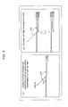
- closed loop type transmission diversity used as specifications in the 3GPP is a method for controlling the transmission carrier phase of the dedicated physical channel (DPCH #2) of the second antenna 10-2 with a resolving power of a carrier phase of ⁇ /4 so that the phases of the reception signals from the two antennas 10-1 and 10-2 are substantially equal to each other in the MS 2, and the following description is given using the method just described as a premise.
- the phase of the CPICH #2 is rotated by the antenna weight estimation. Since the amount of the phase capable of being rotated at this time is equal to the resolving power of the carrier phase of ⁇ /4, there are four patterns of +45°, +135 ° , -135 ° , and -45°.
- the carrier phase (antenna weight) of the DPCH #2 on the BS 1 side remains fixed to 45°.
- the antenna weight estimation sections 237 and 238 calculate the phase rotation amount based only on the history of the FBI bit in the past stored in the FBI bit history storage section 236, and the calculated phase rotation amount is reflected to rotate the CPICH #2 in the direction of -45°.
- the DPCH ⁇ HS-PDSCH demodulation section 234 of the MS 2 demodulates the DPCHs and the HS-PDSCHs based on a synthesis vector of the CPICH #1 and the CPICH #2, in a state illustrated at a lower stage of (2) of FIG. 4 , the phases of the DPCH #1 and the DPCH #2 are opposite to each other and mutually decrease the reception power.
- the phases in the set of the CPICH #1 (#2) and the DPCH #1 (#2) transmitted from the antennas 10-1 and 10-2 are same as each other, if the downward transmission power to the MS 2 decreases, then the TPC acts so as to increase the transmission power of the MS 2.
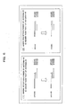
- the transmission of the uplink reaches the BS 1 (in particular, the upward transmission power of the MS 2 does not become less than the reference power necessary for upward synchronism establishment within both periods indicated by reference characters A and B) and the upward synchronism establishment can be implemented.
- the CPICH #2 is rotated in the direction of +135° as illustrated in (2) of FIG. 5 by estimation only with the history of the FBI bit by the antenna verification, for example, from a state illustrated in (1) of FIG. 5 , that is, from the carrier phase relationship illustrated in (1) of FIG. 4 , the phases of the CPICH #2 and the DPCH #2 become opposite to each other.
- the opposite phase state between the DPCH #2 and the CPICH #2 can be eliminated by rotating the DPCH #2 by the antenna verification as described above, since, where the antenna verification is controlled in the OFF state from the beginning, the DPCH #2 cannot be rotated from the phase relationship of the CPICH #2, the MS 2 mistakes the TPC bit and continuously decreases the upward transmission power. As a result, the FBI bit does not reach the BS 1 and the antenna weight estimated by the MS 2 cannot be reflected on the BS 1, and upward synchronism cannot be established within a period A, within which upward synchronism can be established originally, for example, as illustrated in FIG. 9 .
- the antenna verification controlling section 24a by the antenna verification controlling section 24a, the antenna verification is controlled in the ON state before the upward synchronism establishment is detected but the antenna verification is controlled in the OFF state after the point of time, at which the upward synchronism establishment is detected. Consequently, the antenna verification operates within a period of several frames before the FBI bit reaches the BS 1 and then the upward synchronism is established, and therefore, the opposite phase state between the DPCH #1 and the DPCH #2 can be cancelled and the probability that the upward synchronism establishment may result in failure can be decreased.
- the MS 2 starts synchronism establishment setting of the dedicated physical channel (A-DPCH) of the downlink (step S11) and starts synchronism establishment setting of the HS-PDSCH that is the common physical channel of the downlink (step S12).
- the synchronism establishment setting signifies starting of a process for performing, through cooperation between the BB section 23 and the CPU 24, reception timing adjustment of the downlink (A-DPCH, HS-PDSCH) and detecting the synchronizing word (SW) of the downlink.
- the synchronism establishment setting operations of the dedicated physical channel and the common physical channel are executed normally at the same time, the synchronism establishment setting operations may be different from each other as indicated by reference characters T1 and T2 in FIG. 11 .
- the MS 2 starts information transmission of the uplink (DPCH) (step S13) and monitors, by means of the CPU 24, whether or not synchronism of the uplink is established (uplink synchronism establishment monitoring function section 241) (step S14). It is to be noted that, since the transmission and reception timings of the uplink and the downlink are determined in advance in the HSDPA method, establishment of the synchronism of the uplink can be detected by detecting the synchronizing word of the downlink by means of the SIR measurement/TPC detection/SW detection section 233 of the synchronism detection section 23a.
- the MS 2 controls the antenna verification in the ON state so that the antenna weights estimated by the antenna weight estimation sections 237 and 238 are reflected on the SIR measurement/TPC detection/SW detection section 233 and the DPCH ⁇ HS-PDSCH demodulation section 234 (from the N route of step S14 to step S15).
- the MS 2 controls the antenna verification in the OFF state so that the antenna weights estimated by the antenna weight estimation sections 237 and 238 are not reflected on the SIR measurement/TPC detection/SW detection section 233 and the DPCH ⁇ HS-PDSCH demodulation section 234 (from the Y route of step S14 to step S16).
- the MS 2 controls the antenna verification in the ON state within the period after starting of the synchronism establishment setting of the dedicated physical channel and the common physical channel of the downlink till the establishment of the synchronism of the uplink (period from T1 to T4) but controls the antenna verification in the OFF state after the synchronism establishment (T4).
- the antenna weight is carried out.
- the antenna weight estimation by which the DPCH #2 obtains an expected phase, is carried out normally and the CPICH #2 is rotated coaxially (in the same phase) with the DPCH #2 so that such an opposite phase state between the CPICH #2 and the DPCH #2 as illustrated in (2) of FIG. 5 can be cancelled.
- the probability that the TPC bit may be mistaken as described above can be decreased and the probability that synchronism of the uplink can be correctly established can be increased.
- the antenna verification is controlled in the ON state before synchronism establishment of the uplink is detected but the antenna verification is controlled in the OFF state after the synchronism establishment is detected as illustrated in FIGS. 10 and 11
- the antenna verification may be controlled in the ON state before transmission of the uplink is started and the antenna verification may be controlled in the OFF state after the transmission is started, for example, as illustrated in FIGS. 12 and 13 .
- the MS 2 in the present embodiment starts synchronism establishment setting of the dedicated physical channel (A-DPCH) and the common physical channel (HS-PDSCH) of the downlink (steps S11 and S12) and then monitors, by means of the CPU 24, whether or not information transmission of the uplink (DPCH) is started (step S13').
- A-DPCH dedicated physical channel
- HS-PDSCH common physical channel
- the MS 2 controls the antenna verification in the ON state so that the antenna weights estimated by the antenna weight estimation sections 237 and 238 are reflected on the SIR measurement/TPC detection/SW detection section 233 and the DPCH ⁇ HS-PDSCH demodulation section 234 (from an N route of step S13' to step S15).
- the MS 2 controls the antenna verification in the OFF state so that the antenna weights estimated by the antenna weight estimation sections 237 and 238 are not reflected on the SIR measurement/TPC detection/SW detection section 233 and the DPCH ⁇ HS-PDSCH demodulation section 234 (from a Y route of step S13' to step S16).
- the monitoring controlling function in the present embodiment is implemented by providing, as the antenna verification controlling section 24a, functions as an uplink transmission starting monitoring function section 243 for monitoring whether or not transmission starting of the uplink is detected and a second controlling section 244 for controlling the antenna verification by the antenna verification section 23b in the ON state before the transmission starting of the uplink is detected by the monitoring function section 243 but for controlling the antenna verification in the OFF state after the transmission starting of the uplink is detected.
- the MS 2 in the present embodiment controls the antenna verification in the ON state within the period after the synchronism establishment setting starting of the dedicated physical channel and the common physical channel of the downlink till transmission starting of the uplink (period from T1 to T3) but controls the antenna verification in the OFF state after the synchronism establishment (T3).
- appearance of the opposite phase state between the CPICH #2 and the DPCH #2 is a temporal state by the propagation environment, and the antenna verification is controlled from the ON state to the OFF state at a point of time of the transmission starting of the uplink, which is a stage earlier than that in the case of the first embodiment.
- the estimation of the antenna weights (CPICH #2 - DPCH #2) is carried out and then the opposite phase state between the CPICH #2 and the DPCH #2 can be cancelled.
- a probability that the TPC bit may be mistaken as described above can be decreased and the probability that the synchronism of the uplink can be established normally can be increased.
- the embodiments of the present invention can be applied similarly also as in a case wherein the antenna verification is carried out in the bearer of the conventional W-CDMA method (prior to the W-CDMA communication method specification standard 3GPP release 4).
- the DPCH ⁇ HS-PDSCH processing section 11, DPCH ⁇ HS-PDSCH demodulation section 234, DPCH ⁇ HS-PDSCH antenna weight estimation section 238 handle only the DPCH signal.
- the present invention is very useful to the wireless communication technical field.
Landscapes
- Engineering & Computer Science (AREA)
- Computer Networks & Wireless Communication (AREA)
- Signal Processing (AREA)
- Mobile Radio Communication Systems (AREA)
- Radio Transmission System (AREA)
Claims (3)
- Station mobile (2) pour communiquer avec une station de base sans fil (1), ladite station de base sans fil étant configurée pour contrôler la phase des signaux à transmettre à partir de deux antennes (10) en fonction d'une information en retour provenant de la station mobile, la station mobile comportant :une unité de surveillance (24) configurée pour surveiller une phase de communication concernant une liaison ascendante vers la station de base sans fil en réponse à une réception d'un signal provenant de la station de base sans fil ;une unité d'estimation (237, 238) configurée pour estimer la phase des signaux individuels provenant des deux antennes ;un processeur de signal de réception (233, 234) configuré pour mettre en oeuvre un processus de signal de réception à un signal de réception provenant de la station de base sans fil en fonction d'un résultat de l'estimation par l'unité d'estimation ; etun contrôleur (24) configuré pour contrôler un temps de réflexion du résultat d'estimation par l'unité d'estimation sur le processeur de signal de réception en réponse à la phase de communication surveillée par l'unité de surveillance ;dans laquelle l'unité de surveillance comporteune unité de surveillance de début de transmission ascendante (243) configurée pour surveiller si oui ou non une transmission ascendante vers la station de base sans fil est commencée, etle contrôleur comporteun second contrôleur (244) configuré pour amener le résultat d'estimation à réfléchir sur le processus de signal de réception au moins avant que le début de la transmission ascendante soit détecté par l'unité de surveillance de début de transmission ascendante mais pas pour amener le résultat d'estimation à réfléchir sur le processus de signal de réception après que le début de transmission soit détecté.
- Procédé de contrôle de vérification d'antenne pour une station mobile (2) configuré pour communiquer avec une station de base sans fil (1), ladite station de base sans fil étant configurée pour contrôler la phase des signaux à transmettre à partir de deux antennes (10) en fonction d'une information en retour provenant de la station mobile, le procédé de contrôle de vérification d'antenne comportant :la surveillance d'une phase de communication concernant une liaison ascendante vers la station de base sans fil en réponse à une réception d'un signal provenant de la station de base sans fil ;l'estimation de la phase des signaux individuels provenant des deux antennes ;la mise en oeuvre d'un processus de signal de réception à un signal de réception provenant de la station de base sans fil en fonction des résultats de l'estimation lors de l'estimation ; etle contrôle d'un temps de réflexion du résultat d'estimation sur le processus de signal de réception en réponse à la phase de communication surveillée lors de la surveillance ; dans lequel,lors de la surveillance,il est surveillé si oui ou non une transmission ascendante vers la station de base sans fil est commencée, et,lors du contrôle,le résultat d'estimation est amené à réfléchir sur le processus de signal de réception au moins avant que le début de la transmission ascendante soit détecté lors de la surveillance du début de transmission ascendante mais le résultat d'estimation n'est pas amené à réfléchir sur le processus de signal de réception après que le début de la transmission soit détecté.
- Système de communication sans fil comportant la station mobile selon la revendication 1.
Applications Claiming Priority (1)
| Application Number | Priority Date | Filing Date | Title |
|---|---|---|---|
| PCT/JP2006/325097 WO2008072355A1 (fr) | 2006-12-15 | 2006-12-15 | Station mobile et procédé de contrôle de vérification d'antenne sur une station mobile |
Publications (3)
| Publication Number | Publication Date |
|---|---|
| EP2093899A1 EP2093899A1 (fr) | 2009-08-26 |
| EP2093899A4 EP2093899A4 (fr) | 2013-03-06 |
| EP2093899B1 true EP2093899B1 (fr) | 2015-03-04 |
Family
ID=39511387
Family Applications (1)
| Application Number | Title | Priority Date | Filing Date |
|---|---|---|---|
| EP06834824.2A Not-in-force EP2093899B1 (fr) | 2006-12-15 | 2006-12-15 | Station mobile et procédé de contrôle de vérification d'antenne sur une station mobile |
Country Status (5)
| Country | Link |
|---|---|
| US (1) | US8694038B2 (fr) |
| EP (1) | EP2093899B1 (fr) |
| JP (1) | JP4893749B2 (fr) |
| CN (1) | CN101558580B (fr) |
| WO (1) | WO2008072355A1 (fr) |
Families Citing this family (3)
| Publication number | Priority date | Publication date | Assignee | Title |
|---|---|---|---|---|
| AU2006200589A1 (en) * | 2005-02-21 | 2006-09-07 | Nec Australia Pty Ltd | Method for antenna verification |
| US9397742B2 (en) * | 2012-08-21 | 2016-07-19 | Intel Deutschland Gmbh | Receiver circuit and method performed by such receiver circuit |
| US9531483B2 (en) * | 2013-06-19 | 2016-12-27 | Qualcomm Incorporated | Devices and methods for facilitating signal-to-interference ratio estimates for closed-loop transmission diversity communications |
Family Cites Families (11)
| Publication number | Priority date | Publication date | Assignee | Title |
|---|---|---|---|---|
| JP3787269B2 (ja) * | 2000-10-19 | 2006-06-21 | 株式会社エヌ・ティ・ティ・ドコモ | 移動通信システムにおける拡散符号同期方法および受信装置 |
| US7149258B2 (en) * | 2001-11-28 | 2006-12-12 | Telefonaktiebolaget L M Ericsson (Publ) | Method and apparatus for estimation of phase offset between communication channels |
| JP4192572B2 (ja) * | 2002-11-27 | 2008-12-10 | 日本電気株式会社 | 携帯情報端末 |
| JP4198552B2 (ja) * | 2003-07-25 | 2008-12-17 | 株式会社エヌ・ティ・ティ・ドコモ | 無線受信機、無線送信機及びインピーダンス制御方法 |
| US20050042988A1 (en) * | 2003-08-18 | 2005-02-24 | Alcatel | Combined open and closed loop transmission diversity system |
| US7437175B2 (en) * | 2004-05-06 | 2008-10-14 | Telefonaktiebolaget L M Ericsson (Publ) | Synchronization detection methods and apparatus |
| US7715806B2 (en) * | 2004-10-06 | 2010-05-11 | Broadcom Corporation | Method and system for diversity processing including using dedicated pilot method for closed loop |
| JP4751724B2 (ja) * | 2005-01-13 | 2011-08-17 | 株式会社エヌ・ティ・ティ・ドコモ | 移動局装置及び移動局装置の制御方法 |
| JP2006261951A (ja) * | 2005-03-16 | 2006-09-28 | Matsushita Electric Ind Co Ltd | 移動機 |
| JP4594822B2 (ja) * | 2005-08-09 | 2010-12-08 | 株式会社エヌ・ティ・ティ・ドコモ | 受信装置、移動通信システムにおける通信制御方法 |
| US9118111B2 (en) * | 2005-11-02 | 2015-08-25 | Qualcomm Incorporated | Antenna array calibration for wireless communication systems |
-
2006
- 2006-12-15 CN CN2006800566126A patent/CN101558580B/zh not_active Expired - Fee Related
- 2006-12-15 JP JP2008549185A patent/JP4893749B2/ja not_active Expired - Fee Related
- 2006-12-15 EP EP06834824.2A patent/EP2093899B1/fr not_active Not-in-force
- 2006-12-15 WO PCT/JP2006/325097 patent/WO2008072355A1/fr not_active Ceased
-
2009
- 2009-05-15 US US12/466,982 patent/US8694038B2/en not_active Expired - Fee Related
Also Published As
| Publication number | Publication date |
|---|---|
| CN101558580A (zh) | 2009-10-14 |
| WO2008072355A1 (fr) | 2008-06-19 |
| EP2093899A4 (fr) | 2013-03-06 |
| JPWO2008072355A1 (ja) | 2010-03-25 |
| US8694038B2 (en) | 2014-04-08 |
| EP2093899A1 (fr) | 2009-08-26 |
| JP4893749B2 (ja) | 2012-03-07 |
| CN101558580B (zh) | 2013-06-05 |
| US20090227208A1 (en) | 2009-09-10 |
Similar Documents
| Publication | Publication Date | Title |
|---|---|---|
| US7133682B2 (en) | Mobile communication system and communication method for mobile communication system | |
| CN102547950B (zh) | 执行下行链路和/或上行链路功率控制的用户设备和方法 | |
| US7266096B2 (en) | Radio infrastructure apparatus | |
| EP1703755B1 (fr) | Procédé de mesure de l'environnement de communication pour la décision de transfert dans une station mobile | |
| WO2004004164A1 (fr) | Procede de regulation de puissance d'emission et dispositif de station de base | |
| EP1753152B1 (fr) | Systeme de connexion/deconnexion de vérification d'antennes travaillant en diversité de transmission en boucle fermée mode 1 | |
| JP2001285159A (ja) | 移動局装置および送信電力制御方法 | |
| EP1821426B1 (fr) | Appareil de communication mobile et procédé de commande de la puissance de transmission pour ledit appareil | |
| US20060068791A1 (en) | Derivation of optimal antenna weights during soft handover | |
| US6873857B1 (en) | Base station apparatus and transmit power control method | |
| US8285234B2 (en) | Mobile station apparatus | |
| US8694038B2 (en) | Mobile station and antenna verification controlling method for mobile station | |
| US7613432B2 (en) | Method of controlling mobile communication system, control device, and mobile communication system | |
| US20040235508A1 (en) | Transmission rate determination method, and base station apparatus, terminal apparatus, and communication system using the same | |
| JP4523429B2 (ja) | 通信システム、基地局、無線制御装置及び送信電力制御方法 | |
| EP1794897B1 (fr) | Obtention de ponderations d'antennes optimales pendant un transfert intercellulaire sans coupure | |
| US20040105382A1 (en) | Radio reception apparatus | |
| US8295840B2 (en) | Mobile station and feedback information generating method | |
| EP1560351B1 (fr) | Appareil emetteur/recepteur radio | |
| KR100859325B1 (ko) | 이동통신 시스템의 귀환 정보 전송 방법 | |
| EP1931057A1 (fr) | Unité mobile, système de communication mobile et procédé de vérification d'antenne | |
| EP1447932A1 (fr) | Recepteur sans fil |
Legal Events
| Date | Code | Title | Description |
|---|---|---|---|
| PUAI | Public reference made under article 153(3) epc to a published international application that has entered the european phase |
Free format text: ORIGINAL CODE: 0009012 |
|
| 17P | Request for examination filed |
Effective date: 20090708 |
|
| AK | Designated contracting states |
Kind code of ref document: A1 Designated state(s): AT BE BG CH CY CZ DE DK EE ES FI FR GB GR HU IE IS IT LI LT LU LV MC NL PL PT RO SE SI SK TR |
|
| DAX | Request for extension of the european patent (deleted) | ||
| A4 | Supplementary search report drawn up and despatched |
Effective date: 20130131 |
|
| RIC1 | Information provided on ipc code assigned before grant |
Ipc: H04B 1/707 20110101ALI20130125BHEP Ipc: H04B 7/06 20060101AFI20130125BHEP Ipc: H04B 7/26 20060101ALI20130125BHEP |
|
| 17Q | First examination report despatched |
Effective date: 20131025 |
|
| GRAP | Despatch of communication of intention to grant a patent |
Free format text: ORIGINAL CODE: EPIDOSNIGR1 |
|
| INTG | Intention to grant announced |
Effective date: 20141002 |
|
| GRAS | Grant fee paid |
Free format text: ORIGINAL CODE: EPIDOSNIGR3 |
|
| GRAA | (expected) grant |
Free format text: ORIGINAL CODE: 0009210 |
|
| AK | Designated contracting states |
Kind code of ref document: B1 Designated state(s): AT BE BG CH CY CZ DE DK EE ES FI FR GB GR HU IE IS IT LI LT LU LV MC NL PL PT RO SE SI SK TR |
|
| REG | Reference to a national code |
Ref country code: GB Ref legal event code: FG4D |
|
| REG | Reference to a national code |
Ref country code: CH Ref legal event code: EP |
|
| REG | Reference to a national code |
Ref country code: IE Ref legal event code: FG4D |
|
| REG | Reference to a national code |
Ref country code: AT Ref legal event code: REF Ref document number: 714649 Country of ref document: AT Kind code of ref document: T Effective date: 20150415 |
|
| REG | Reference to a national code |
Ref country code: DE Ref legal event code: R096 Ref document number: 602006044724 Country of ref document: DE Effective date: 20150416 |
|
| REG | Reference to a national code |
Ref country code: AT Ref legal event code: MK05 Ref document number: 714649 Country of ref document: AT Kind code of ref document: T Effective date: 20150304 Ref country code: NL Ref legal event code: VDEP Effective date: 20150304 |
|
| PG25 | Lapsed in a contracting state [announced via postgrant information from national office to epo] |
Ref country code: FI Free format text: LAPSE BECAUSE OF FAILURE TO SUBMIT A TRANSLATION OF THE DESCRIPTION OR TO PAY THE FEE WITHIN THE PRESCRIBED TIME-LIMIT Effective date: 20150304 Ref country code: LT Free format text: LAPSE BECAUSE OF FAILURE TO SUBMIT A TRANSLATION OF THE DESCRIPTION OR TO PAY THE FEE WITHIN THE PRESCRIBED TIME-LIMIT Effective date: 20150304 Ref country code: SE Free format text: LAPSE BECAUSE OF FAILURE TO SUBMIT A TRANSLATION OF THE DESCRIPTION OR TO PAY THE FEE WITHIN THE PRESCRIBED TIME-LIMIT Effective date: 20150304 Ref country code: ES Free format text: LAPSE BECAUSE OF FAILURE TO SUBMIT A TRANSLATION OF THE DESCRIPTION OR TO PAY THE FEE WITHIN THE PRESCRIBED TIME-LIMIT Effective date: 20150304 |
|
| REG | Reference to a national code |
Ref country code: LT Ref legal event code: MG4D |
|
| PG25 | Lapsed in a contracting state [announced via postgrant information from national office to epo] |
Ref country code: GR Free format text: LAPSE BECAUSE OF FAILURE TO SUBMIT A TRANSLATION OF THE DESCRIPTION OR TO PAY THE FEE WITHIN THE PRESCRIBED TIME-LIMIT Effective date: 20150605 Ref country code: LV Free format text: LAPSE BECAUSE OF FAILURE TO SUBMIT A TRANSLATION OF THE DESCRIPTION OR TO PAY THE FEE WITHIN THE PRESCRIBED TIME-LIMIT Effective date: 20150304 Ref country code: AT Free format text: LAPSE BECAUSE OF FAILURE TO SUBMIT A TRANSLATION OF THE DESCRIPTION OR TO PAY THE FEE WITHIN THE PRESCRIBED TIME-LIMIT Effective date: 20150304 |
|
| PG25 | Lapsed in a contracting state [announced via postgrant information from national office to epo] |
Ref country code: NL Free format text: LAPSE BECAUSE OF FAILURE TO SUBMIT A TRANSLATION OF THE DESCRIPTION OR TO PAY THE FEE WITHIN THE PRESCRIBED TIME-LIMIT Effective date: 20150304 |
|
| PG25 | Lapsed in a contracting state [announced via postgrant information from national office to epo] |
Ref country code: CZ Free format text: LAPSE BECAUSE OF FAILURE TO SUBMIT A TRANSLATION OF THE DESCRIPTION OR TO PAY THE FEE WITHIN THE PRESCRIBED TIME-LIMIT Effective date: 20150304 Ref country code: SK Free format text: LAPSE BECAUSE OF FAILURE TO SUBMIT A TRANSLATION OF THE DESCRIPTION OR TO PAY THE FEE WITHIN THE PRESCRIBED TIME-LIMIT Effective date: 20150304 Ref country code: RO Free format text: LAPSE BECAUSE OF FAILURE TO SUBMIT A TRANSLATION OF THE DESCRIPTION OR TO PAY THE FEE WITHIN THE PRESCRIBED TIME-LIMIT Effective date: 20150304 Ref country code: EE Free format text: LAPSE BECAUSE OF FAILURE TO SUBMIT A TRANSLATION OF THE DESCRIPTION OR TO PAY THE FEE WITHIN THE PRESCRIBED TIME-LIMIT Effective date: 20150304 Ref country code: PT Free format text: LAPSE BECAUSE OF FAILURE TO SUBMIT A TRANSLATION OF THE DESCRIPTION OR TO PAY THE FEE WITHIN THE PRESCRIBED TIME-LIMIT Effective date: 20150706 |
|
| REG | Reference to a national code |
Ref country code: FR Ref legal event code: PLFP Year of fee payment: 10 |
|
| PG25 | Lapsed in a contracting state [announced via postgrant information from national office to epo] |
Ref country code: PL Free format text: LAPSE BECAUSE OF FAILURE TO SUBMIT A TRANSLATION OF THE DESCRIPTION OR TO PAY THE FEE WITHIN THE PRESCRIBED TIME-LIMIT Effective date: 20150304 Ref country code: IS Free format text: LAPSE BECAUSE OF FAILURE TO SUBMIT A TRANSLATION OF THE DESCRIPTION OR TO PAY THE FEE WITHIN THE PRESCRIBED TIME-LIMIT Effective date: 20150704 |
|
| REG | Reference to a national code |
Ref country code: DE Ref legal event code: R097 Ref document number: 602006044724 Country of ref document: DE |
|
| PG25 | Lapsed in a contracting state [announced via postgrant information from national office to epo] |
Ref country code: IT Free format text: LAPSE BECAUSE OF FAILURE TO SUBMIT A TRANSLATION OF THE DESCRIPTION OR TO PAY THE FEE WITHIN THE PRESCRIBED TIME-LIMIT Effective date: 20150304 |
|
| PLBE | No opposition filed within time limit |
Free format text: ORIGINAL CODE: 0009261 |
|
| STAA | Information on the status of an ep patent application or granted ep patent |
Free format text: STATUS: NO OPPOSITION FILED WITHIN TIME LIMIT |
|
| PG25 | Lapsed in a contracting state [announced via postgrant information from national office to epo] |
Ref country code: DK Free format text: LAPSE BECAUSE OF FAILURE TO SUBMIT A TRANSLATION OF THE DESCRIPTION OR TO PAY THE FEE WITHIN THE PRESCRIBED TIME-LIMIT Effective date: 20150304 |
|
| 26N | No opposition filed |
Effective date: 20151207 |
|
| PG25 | Lapsed in a contracting state [announced via postgrant information from national office to epo] |
Ref country code: SI Free format text: LAPSE BECAUSE OF FAILURE TO SUBMIT A TRANSLATION OF THE DESCRIPTION OR TO PAY THE FEE WITHIN THE PRESCRIBED TIME-LIMIT Effective date: 20150304 |
|
| PG25 | Lapsed in a contracting state [announced via postgrant information from national office to epo] |
Ref country code: BE Free format text: LAPSE BECAUSE OF NON-PAYMENT OF DUE FEES Effective date: 20151231 |
|
| PG25 | Lapsed in a contracting state [announced via postgrant information from national office to epo] |
Ref country code: MC Free format text: LAPSE BECAUSE OF FAILURE TO SUBMIT A TRANSLATION OF THE DESCRIPTION OR TO PAY THE FEE WITHIN THE PRESCRIBED TIME-LIMIT Effective date: 20150304 Ref country code: LU Free format text: LAPSE BECAUSE OF FAILURE TO SUBMIT A TRANSLATION OF THE DESCRIPTION OR TO PAY THE FEE WITHIN THE PRESCRIBED TIME-LIMIT Effective date: 20151215 |
|
| REG | Reference to a national code |
Ref country code: CH Ref legal event code: PL |
|
| PG25 | Lapsed in a contracting state [announced via postgrant information from national office to epo] |
Ref country code: BE Free format text: LAPSE BECAUSE OF FAILURE TO SUBMIT A TRANSLATION OF THE DESCRIPTION OR TO PAY THE FEE WITHIN THE PRESCRIBED TIME-LIMIT Effective date: 20150304 |
|
| REG | Reference to a national code |
Ref country code: IE Ref legal event code: MM4A |
|
| PG25 | Lapsed in a contracting state [announced via postgrant information from national office to epo] |
Ref country code: LI Free format text: LAPSE BECAUSE OF NON-PAYMENT OF DUE FEES Effective date: 20151231 Ref country code: IE Free format text: LAPSE BECAUSE OF NON-PAYMENT OF DUE FEES Effective date: 20151215 Ref country code: CH Free format text: LAPSE BECAUSE OF NON-PAYMENT OF DUE FEES Effective date: 20151231 |
|
| REG | Reference to a national code |
Ref country code: FR Ref legal event code: PLFP Year of fee payment: 11 |
|
| PG25 | Lapsed in a contracting state [announced via postgrant information from national office to epo] |
Ref country code: HU Free format text: LAPSE BECAUSE OF FAILURE TO SUBMIT A TRANSLATION OF THE DESCRIPTION OR TO PAY THE FEE WITHIN THE PRESCRIBED TIME-LIMIT; INVALID AB INITIO Effective date: 20061215 Ref country code: BG Free format text: LAPSE BECAUSE OF FAILURE TO SUBMIT A TRANSLATION OF THE DESCRIPTION OR TO PAY THE FEE WITHIN THE PRESCRIBED TIME-LIMIT Effective date: 20150304 |
|
| PG25 | Lapsed in a contracting state [announced via postgrant information from national office to epo] |
Ref country code: CY Free format text: LAPSE BECAUSE OF FAILURE TO SUBMIT A TRANSLATION OF THE DESCRIPTION OR TO PAY THE FEE WITHIN THE PRESCRIBED TIME-LIMIT Effective date: 20150304 |
|
| PG25 | Lapsed in a contracting state [announced via postgrant information from national office to epo] |
Ref country code: TR Free format text: LAPSE BECAUSE OF FAILURE TO SUBMIT A TRANSLATION OF THE DESCRIPTION OR TO PAY THE FEE WITHIN THE PRESCRIBED TIME-LIMIT Effective date: 20150304 |
|
| REG | Reference to a national code |
Ref country code: FR Ref legal event code: PLFP Year of fee payment: 12 |
|
| PGFP | Annual fee paid to national office [announced via postgrant information from national office to epo] |
Ref country code: FR Payment date: 20171113 Year of fee payment: 12 Ref country code: DE Payment date: 20171212 Year of fee payment: 12 |
|
| PGFP | Annual fee paid to national office [announced via postgrant information from national office to epo] |
Ref country code: GB Payment date: 20171213 Year of fee payment: 12 |
|
| REG | Reference to a national code |
Ref country code: DE Ref legal event code: R119 Ref document number: 602006044724 Country of ref document: DE |
|
| GBPC | Gb: european patent ceased through non-payment of renewal fee |
Effective date: 20181215 |
|
| PG25 | Lapsed in a contracting state [announced via postgrant information from national office to epo] |
Ref country code: DE Free format text: LAPSE BECAUSE OF NON-PAYMENT OF DUE FEES Effective date: 20190702 Ref country code: FR Free format text: LAPSE BECAUSE OF NON-PAYMENT OF DUE FEES Effective date: 20181231 |
|
| PG25 | Lapsed in a contracting state [announced via postgrant information from national office to epo] |
Ref country code: GB Free format text: LAPSE BECAUSE OF NON-PAYMENT OF DUE FEES Effective date: 20181215 |