EP2093915A1 - Zeitsynchronisierung in einem Netzwerk - Google Patents
Zeitsynchronisierung in einem Netzwerk Download PDFInfo
- Publication number
- EP2093915A1 EP2093915A1 EP08151616A EP08151616A EP2093915A1 EP 2093915 A1 EP2093915 A1 EP 2093915A1 EP 08151616 A EP08151616 A EP 08151616A EP 08151616 A EP08151616 A EP 08151616A EP 2093915 A1 EP2093915 A1 EP 2093915A1
- Authority
- EP
- European Patent Office
- Prior art keywords
- time
- synchronization
- subunit
- master
- information
- Prior art date
- Legal status (The legal status is an assumption and is not a legal conclusion. Google has not performed a legal analysis and makes no representation as to the accuracy of the status listed.)
- Withdrawn
Links
Images
Classifications
-
- H—ELECTRICITY
- H04—ELECTRIC COMMUNICATION TECHNIQUE
- H04L—TRANSMISSION OF DIGITAL INFORMATION, e.g. TELEGRAPHIC COMMUNICATION
- H04L7/00—Arrangements for synchronising receiver with transmitter
- H04L7/0008—Synchronisation information channels, e.g. clock distribution lines
-
- H—ELECTRICITY
- H04—ELECTRIC COMMUNICATION TECHNIQUE
- H04L—TRANSMISSION OF DIGITAL INFORMATION, e.g. TELEGRAPHIC COMMUNICATION
- H04L7/00—Arrangements for synchronising receiver with transmitter
- H04L7/04—Speed or phase control by synchronisation signals
- H04L7/041—Speed or phase control by synchronisation signals using special codes as synchronising signal
- H04L7/044—Speed or phase control by synchronisation signals using special codes as synchronising signal using a single bit, e.g. start stop bit
Definitions
- the present invention relates to a method and a system for time synchronization in a network of communicating units, comprising a master unit holding information on a master time, and at least one subunit having a clock, which is to be synchronized with the master time, wherein the units communicates with each other by means of radio communication signals carrying information sent via a hollow transmission device, also denoted a waveguide, which is shaped to allow wireless transmitting of said radio communication signals between the units.
- the present invention also relates to a system for time synchronization in a network of communicating units, wherein the system comprises: a master unit holding information on a master time, and at least one subunit having a clock, which is to be synchronized with the master time, wherein the units communicates with each other by means of radio communication signals carrying information sent via a hollow transmission device, which is shaped to allow wireless transmitting of said radio communication signals between the units.
- the invention is applicable in synchronization of clocks in a network of communicating units, where the communication is transmitted through a waveguide, for example in electric substations.
- Another example on applications for the invention is time-synchronization of sensors in paper-mills, where the communication is transmitted through a fully of partially enclosed frame structure.
- the main function of an electrical substation is to distribute and transform electrical power. For instance, one basic task is to switch down the voltage of distributed power to suitable levels which are useful for a wide range of users, such as utilities companies and various types of plants, etc.
- a waveguide is a structure arranged to guide waves, for example radio waves, between different physical locations.
- a waveguide besides guiding the waves, also shields radio waves from interference and electromagnetic noise.
- a waveguide comprises an enclosure usually having a parallelepiped structure.
- a waveguide is suitable to be used for radio communication between units in a network, such as units within a substation.
- the units of the network can have internal clocks to time stamp events in the operation.
- large amount of operational events can occur within a short time period, such as during a malfunction event in a network, for example a short circuit within a substation.
- To evaluate the cause of the malfunction it is important to reliably establish the time of each event for each unit within the network. Therefore, an accurate time synchronization of the units within the network is needed for the analysis.
- a waveguide for radio communication between units in a network has the disadvantage that traditional time synchronization is low in accuracy due to disturbances and jitter in the system, resulting typically in a synchronization error of about 1 ms.
- a more accurate time synchronization for example a synchronization error in the order of less than 100 ⁇ s, is needed for a reliable analysis of events during operation.
- waveguide adapted for wireless communication in an electrical switchboard
- the waveguide comprises an anti-interference shielding layer reducing signal interferences and disturbances, which could affect the quality and reliability of the signals during transmissions.
- radio communication of control signals within a substation is performed utilizing a waveguide to transmit and shield signals from interference and noise.
- One object of the present invention is to provide an improved method for time synchronization in a network of communicating units.
- Such a method comprising: sending information including a point in time for a synchronization event from the master unit to the subunit on the first channel, receiving and storing said information on the point of time for the synchronization event in the subunit, sending a time synchronization signal from the master unit to the subunit on the second channel, when said point of time for synchronization occurs in the master time, and adjusting the clock of the subunit upon receiving the time synchronization signal according to the stored information on time for the synchronization event.
- the solution to the above described problem with the time synchronization in a network of communicating units is solved with a method, where the first radio channel, which is used for communications within the network, is configured to transmit the information of the point in time for the synchronization event, which is to occur in the future according to the master time, and a second radio channel configured to transmit the time synchronization signal.
- the information on time for the synchronization event contains data on the point of time, in respect to the master time of the master unit, when the master unit will send the synchronization signal to the subunit, and the data will be used to adjust the clock of the subunit upon receiving the time synchronization signal.
- the information on the point of time for the synchronization event is sent from the master unit to the subunit prior to the time for the synchronization event, according to the master time of the master unit.
- the subunit receives and stores the information on the point of time for the synchronization event prior to the time for the synchronization event, according to the master time of the master unit.
- the master unit When the point of time for the synchronization occurs according to the master time, the master unit sends a time synchronization signal to the subunit on the second radio channel.
- the second channel is configured to exclusively transmit the time synchronization signal from the master unit to the subunit. Thereby, the time synchronization signal is transmitted reliably and quickly, with small jitter and latency, without interference from the master unit to the subunit.
- the second channel can be a simple radio channel, arranged from hardware of low cost.
- the time synchronization signal is configured to, upon being received by the subunit, trigger an adjustment of the clock of the subunit, according to the stored information on the point of time for the synchronization event in the subunit.
- the radio channels can be separated by time division, frequency division, or code division, or any combination thereof. This means that the radio signals on the separate channels differ in time, frequency, or code.
- the invention improves the accuracy of the time synchronization of the network of communicating units, by separating in respect to time and radio channel, the transmission of the information on the point of time for the synchronization event from the transmission of the time synchronization signal.
- the transmission of data is achieved with a higher success probability and smaller jitter, due to less data retransmission or busy media, on a radio channel with little data load than on a radio channel with much data load.
- the transmission of the signal is achieved with higher precision and success probability than if the transmission would be performed on a radio channel shared with other communication.
- the transmission of the time synchronization signal from the master unit to the subunit is achieved with higher precision than if the information on the point of time for the synchronization event and the time synchronization signal would be transmitted at a single time and on a single radio channel, and consequently the accuracy of the time synchronization operation is improved.
- the uncertainty in the transmittal time for the information on the point of time for the synchronization event is not critical to the accuracy of the time synchronization operation.
- the accuracy of the time synchronization is dependent on the jitter of the transmission of the time synchronization signal from the master unit to the subunit. Thereby, the accuracy of the time synchronization of the network of communicating units is improved when a separate, dedicated radio channel with low interference level is used for the synchronization event.
- the method further comprises sending the time synchronization signal in form of a pulse.
- the time synchronization signal is in the form of a pulse.
- the transmission of data is achieved more reliably and with lower jitter on a radio channel with little data load than on a radio channel with much data load.
- the time synchronization signal comprises a simple form of data that is transmitted quickly, with little jitter and latency, from the master unit to the subunit. Thereby, the accuracy of the time synchronization of the network of communicating units is improved.
- the second radio channel can be arranged from hardware of low cost.
- the method further comprises receiving a master time at the master unit from an external time source, such as a Global Positioning System (GPS) receiver.
- an external time source such as a Global Positioning System (GPS) receiver.
- GPS Global Positioning System
- the master unit receives the master time from an external time source.
- the master time from the external time source can be used for time synchronization of a plurality of networks of communicating units.
- the method further comprises sending the information on the point of time for the synchronization event on a two way communication channel.
- the first channel is used for the ordinary communication in the network. Since the information is sent prio to the time of the synchronization, the jitter and latency of the channel is not limiting the accuracy of the time synchronization operation. Thereby, no additional or separate channel is need for the transmittal of the information on the point of time for the synchronization event.
- the method further comprises sending the time synchronization signal on a one way communication channel.
- the second channel can be can be arranged from hardware of low cost.
- the method further comprises measuring the time difference between receiving the information on the point of time for the synchronization event at the subunit and receiving the time synchronization signal at the subunit, comparing said measured time with a set value, and canceling the time synchronization if said measured time difference exceeds the set value.
- the subunit is measuring the time difference between receiving the information on the point of time for the synchronization event at the subunit and receiving the time synchronization signal at the subunit.
- the time difference is measured by the clock of the subunit.
- the measured time difference by the subunit is compared with a set value.
- the set value is stored in the subunit, and is a value in a time unit, such as second. If the measured time difference exceeds the set value, the subunit cancels the time synchronization. By canceling the time synchronization, the subunit does not adjust the clock upon receiving the time synchronization signal, according to the stored information on the point of time for the synchronization event.
- the stored information on the point of time for the synchronization event in the subunit is no longer valid for the time synchronization. If the time synchronization has been canceled, the subunit needs to receive new information on the point of time for the synchronization event, before receiving the time synchronization signal. By setting a maximum value on the time difference between receiving the information on the point of time for the synchronization event at the subunit and receiving the time synchronization signal at the subunit, the risk of incorrect time synchronization is reduced.
- One object of the present invention is to provide an improved system for time synchronization in a network of communicating units.
- Such a system comprising a first and a second radio channel, the master unit is configured to send information including a point in time for a synchronization event on the first channel to the subunit, the master unit is further configured to send a time synchronization signal to the subunit on the second channel, when said point of time for synchronization occurs in the master time, the subunit is configured to receive and store said information, the subunit is configured to adjust the clock upon receiving the time synchronization signal according to the stored information on time for the synchronization event.
- the system according to the invention is advantageously used for the synchronization between communicating units in a network in a substation.
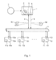
- Figure 1 shows an example of a system for time synchronization in a network of communicating units according to the invention.
- the system comprises a master unit 1 holding information on a master time.
- the master unit 1 includes an internal clock 2, which holds the master time.
- the clock 2 of the master unit 1 is updated from an external time source 3, for example a GPS device.
- the master units receives the master time from an external clock.
- the internal clock 2 of the master unit 1 is having the master time that is used for the time synchronization.
- the system further comprises a plurality of subunits 10a-10i each having a clock 11a-11i, which is to be synchronized with the master time.
- the units communicates with each other by means of radio communication signals carrying information sent via a hollow transmission device 7, also known as a waveguide, which is shaped to allow wireless transmitting of the radio communication signals between the units.
- the system has a first 8 and a second radio channel 9.
- the master unit 1 is configured to send information 8d including a point in time for a synchronization event on the first channel 8 to the subunits 10a-10i.
- the master unit 1 is further configured to send a time synchronization signal 9d to the subunits 10a-10i on the second channel 9, when the point of time for synchronization occurs in the master time.
- the subunits 10a-10i are configured to receive and store the point in time for the synchronization event 8d.
- the subunits 10a-10i are configured to adjust the clocks 11a-11i upon receiving the time synchronization signal 9d according to the stored time for the synchronization event.
- the first channel 8 is used for sending the information 8d from the master unit 1 to the subunits 10a-10i for the synchronization of the clocks 11a-11i.
- the first radio channel can be a one way communication channel from the master unit to the subunits. However more preferable, if a two way communication channel is used between the master unit and the subunits, then it is possible to use the first channel for the ordinary communication between the master unit and the subunits. Thereby, for synchronization purpose, it is enough to have one channel in addition to the channel for the ordinary communication in network.
- the ordinary communication on the first channel can be various types of data, such as control or operational data in an electrical substation.
- the second channel 9 is used for sending the time synchronization signal 9d from the master unit 1 to the subunits 10a-10i for the synchronization of the clocks 11a-11i.
- the second channel can be a two way communication channel between the master units to the subunits.
- the second channel can be arranged from hardware of low cost.
- the second channel is configured to be separated from other communication in the network. Thereby, the signals are transmitted with low jitter and latency, without interference from other communication in the network, resulting in high accuracy of the time synchronization of the clocks.
- the second channel is adapted for transmission of signals in form of a pulse, the second radio channel can be arranged from hardware of low cost.
- the master unit 1 communicates with the subunits 10a-10i of the network.
- the communication is of various types, such as control or operational data in an electrical substation.
- the master unit uses the master time for the time synchronization of the subunits.
- the master unit has two functions in the time synchronization of the subunits. Firstly, the information including the point in time for the synchronization event 8d, according to the master time of the master unit, is sent from the master unit to the subunits on the first radio channel 8. The information is sent prior to the time of the synchronization, according to the master time. Secondly, when the point of time for the synchronization occurs in the master time, the master unit sends the time synchronization signal 9d to the subunits on the second channel 9.
- the master unit 1 most preferably includes a transceiver 5, configured to send and receive the information 8d on the first radio channel 8 between the master unit 1 and the subunits 10a-10i, as shown in figure 1 .
- the first channel can also be configured for a one way communication channel from the master unit to the subunits, and the transceiver is then replaced by a transmitter.
- the ordinary communication in the network between the master unit and the subunits needs to be performed on a third channel, which is adapted for a two way communication.
- the master unit 1 further most preferably includes a transmitter 6, configured to send the synchronization signal 9d on the second channel 9 from the master unit to the subunits, as shown in figure 1 .
- the second channel can also be configured for a two way communication channel between the master unit and the subunits, and the transmitter is then replaced by a transceiver.
- the subunits 10a-10i of the network communicates with the master unit 1.
- the subunits send information, such as operational data, to the master unit.
- Each of the subunits has a clock 11a-11i that is used for time stamp information, such as the time of an operational event.
- the subunits have two functions in the time synchronization. Firstly, the subunits receive and store the information including the point of time for the synchronization event 8d, transmitted from the master unit. Secondly, the subunits receive the time synchronization signal 9d from the master unit, and the clocks of the subunits are thereafter adjusted according to the stored information on time for the synchronization event. Thereby, the synchronization event has been completed, and the clocks of the subunits have been time synchronized with the master time of the master unit.
- the subunits 10a-10i preferably include transceivers 12a-12i, configured to send and receive the information 8d on the first radio channel 8 between the master unit 1 and the subunits, as shown in figure 1 . If, in a less preferable case, the first radio channel 8 is configured for a one way communication, the transceiver can be replaced by receivers.
- the subunits further preferably include receivers 13a-13i for receiving signals on the second radio channel 9. If, in a less preferable case, the second radio channel 9 is configured for a two way communication, the receivers can be replaced by transceivers.
- the information on the time for the synchronization event 8d contains data on the point of time, for example the point in time specified down to nanoseconds, in respect to the master time, for the time synchronization event.
- the information is sent prior to the synchronization event, from the master unit 1 to the subunits 10a-10i, according to the master time, on the first radio channel.
- the information is used for adjusting the clocks 11a-11i of the subunits upon receiving the time synchronization signal 9d.
- the time synchronization signal 9d is sent from the master unit 1 to the subunits 10a-10i at the point of time for the synchronization event, according to the master time.
- the time synchronization signal is a signal that triggers an adjustment of the clocks 11a-11i of the subunits according to the stored information on the time for the synchronization event 8d.
- the time synchronization signal is in an embodiment of the invention configured to be a pulse.
- the transmission of the signal 9d from the master unit 1 to the subunits 10a-10i is performed quickly, with small jitter and latency, resulting in an accurate time synchronization of the clocks 11a-11i.
- the radio channel for transmitting the synchronization signal in form of a pulse can be arranged from hardware of low cost.
- the signal transmission device 7 also known as a waveguide, is used to allow wireless transmitting of the radio communication signals between the master unit 1 and the subunits 10a-10i.
- the waveguide connects the antennas of the transceiver devices and allows the units of the network to communicate with each other.
- the waveguide has a tubular shape with a rectangular profile.
- One side of the waveguide is provided with openings for connecting the antennas of the transceiver or transmitter devices.
- the waveguide 7 encloses the antennas, and shields the transmitted radio signals against interference with the surrounding.
- Most electromagnetic shielding material can be chosen for the waveguide, for example aluminum or copper.
- the dimension of the waveguide depends on the frequency of the radio communication signals.
- the function waveguide is to guiding the waves between the units of the network, and also to shield the radio waves from interference and electromagnetic noise.
- the communication in the network of communicating units is performed by means of radio communication signals, for example, based on an Ethernet based standard IEC 61850.
- the units of the network include communication modules configured to modulate a signal carrying information onto a radio frequency wave, or demodulate a signal carrying information from a radio frequency wave, such as transceiver, transmitter, and receiver devices.
- the radio frequency wave preferably has a frequency in the interval 0.1 - 70GHz, more preferably in the interval 1 - 20GHz, and most preferably in the interval 2 - 10GHz.
- each communication unit comprises an antenna for transmitting and/or receiving radio frequency waves connected to the communication module.
- the time difference between receiving the information on the point of time for the synchronization event 8d at the subunits 10a-10i and receiving the time synchronization signal 9d at the subunits is measured.
- the measured time difference is compared to a set value. If the measured time difference exceeds the set value, the time synchronization is canceled. Thus, the clocks 11a-11i of the subunits will not be changed upon receiving the time synchronization signal 9d.
- the subunits first needs to receive new information on the point of time for a synchronization event 8d. Thereafter, if the subunits receive a new time synchronization signal 9d within the time difference of the set value, the clocks of the subunits will be adjusted. By setting a maximum value on the time difference between receiving the information on the point of time for the synchronization event at the subunit and receiving the time synchronization signal at the subunit, the risk of incorrect time synchronization is reduced.
- the synchronization method comprises sending information including a point in time for a synchronization event from the master unit to the subunit on the first radio channel.
- the point of time for the time synchronization in the future, according to the master time is transmitted to the subunits.
- the transmittal time and jitter of the information is not critical for the accuracy of the time synchronization.
- the subunits receive and store the information on the point of time for the synchronization event. Thereby, the subunits have stored the necessary information for adjusting the clocks, when the point of time for the synchronization occurs in the master time.
- the time synchronization signal is sent from the master unit to the subunit on the second channel, when the point of time for synchronization occurs in the master time.
- a signal is sent from the master unit to the subunit that triggers an adjustment of the clocks of the subunits.
- the clock of the subunit is adjusted according to the stored information on time for the synchronization event.
- the method improves the accuracy of the time synchronization by sending the information on the point of time for the synchronization event from the master unit to the subunits, on the first radio channel, which has a varying transmission latency and jitter, prior to the time of the synchronization, according to the master time.
- the time synchronization signal is sent from the master unit to the subunits on the second radio channel, which has a known small latency with a small jitter.
- the method improves the accuracy of the time synchronization operation.
Landscapes
- Engineering & Computer Science (AREA)
- Computer Networks & Wireless Communication (AREA)
- Signal Processing (AREA)
- Synchronisation In Digital Transmission Systems (AREA)
- Electric Clocks (AREA)
- Mobile Radio Communication Systems (AREA)
Priority Applications (1)
| Application Number | Priority Date | Filing Date | Title |
|---|---|---|---|
| EP08151616A EP2093915A1 (de) | 2008-02-19 | 2008-02-19 | Zeitsynchronisierung in einem Netzwerk |
Applications Claiming Priority (1)
| Application Number | Priority Date | Filing Date | Title |
|---|---|---|---|
| EP08151616A EP2093915A1 (de) | 2008-02-19 | 2008-02-19 | Zeitsynchronisierung in einem Netzwerk |
Publications (1)
| Publication Number | Publication Date |
|---|---|
| EP2093915A1 true EP2093915A1 (de) | 2009-08-26 |
Family
ID=39587964
Family Applications (1)
| Application Number | Title | Priority Date | Filing Date |
|---|---|---|---|
| EP08151616A Withdrawn EP2093915A1 (de) | 2008-02-19 | 2008-02-19 | Zeitsynchronisierung in einem Netzwerk |
Country Status (1)
| Country | Link |
|---|---|
| EP (1) | EP2093915A1 (de) |
Citations (7)
| Publication number | Priority date | Publication date | Assignee | Title |
|---|---|---|---|---|
| US5697051A (en) * | 1993-08-11 | 1997-12-09 | Glenayre Electronics, Inc. | Method for coordinating propagation delays in a satellite linked simulcast network using a benchmark station |
| WO1999062216A2 (en) * | 1998-05-28 | 1999-12-02 | Koninklijke Philips Electronics N.V. | Method of timestamp synchronization of a reservation-based tdma protocol |
| US6236623B1 (en) * | 1998-10-16 | 2001-05-22 | Moore Industries | System and method for synchronizing clocks in a plurality of devices across a communication channel |
| EP1239600A1 (de) | 2001-03-07 | 2002-09-11 | Abb Research Ltd. | Drahtloses Kommunikationssystem mit Wellenleiter |
| EP1324520A2 (de) * | 2001-12-24 | 2003-07-02 | Agilent Technologies, Inc. | Synchronisierung in einem verteilten System |
| EP1701420A1 (de) | 2005-03-07 | 2006-09-13 | ABB Technology AG | Elektrischer Verteiler und Mittelspannungsstation mit einem derartigen Verteiler |
| EP1802015A1 (de) * | 2005-12-23 | 2007-06-27 | Agilent Technologies, Inc. | Beseitigung von Verzögerungsschwankungen bei der Netzwerkzeitsynchronisierung |
-
2008
- 2008-02-19 EP EP08151616A patent/EP2093915A1/de not_active Withdrawn
Patent Citations (7)
| Publication number | Priority date | Publication date | Assignee | Title |
|---|---|---|---|---|
| US5697051A (en) * | 1993-08-11 | 1997-12-09 | Glenayre Electronics, Inc. | Method for coordinating propagation delays in a satellite linked simulcast network using a benchmark station |
| WO1999062216A2 (en) * | 1998-05-28 | 1999-12-02 | Koninklijke Philips Electronics N.V. | Method of timestamp synchronization of a reservation-based tdma protocol |
| US6236623B1 (en) * | 1998-10-16 | 2001-05-22 | Moore Industries | System and method for synchronizing clocks in a plurality of devices across a communication channel |
| EP1239600A1 (de) | 2001-03-07 | 2002-09-11 | Abb Research Ltd. | Drahtloses Kommunikationssystem mit Wellenleiter |
| EP1324520A2 (de) * | 2001-12-24 | 2003-07-02 | Agilent Technologies, Inc. | Synchronisierung in einem verteilten System |
| EP1701420A1 (de) | 2005-03-07 | 2006-09-13 | ABB Technology AG | Elektrischer Verteiler und Mittelspannungsstation mit einem derartigen Verteiler |
| EP1802015A1 (de) * | 2005-12-23 | 2007-06-27 | Agilent Technologies, Inc. | Beseitigung von Verzögerungsschwankungen bei der Netzwerkzeitsynchronisierung |
Similar Documents
| Publication | Publication Date | Title |
|---|---|---|
| EP3055938B1 (de) | Systeme und verfahren zur verzögerungsverwaltung in einem verteilten antennensystem mit direkter digitaler schnittstelle zu einer basisstation | |
| CN106068579B (zh) | 具有分布式收发器系统的有源天线系统 | |
| EP2502371B1 (de) | Overhead-anpassungsschema für passive optische netzwerke | |
| MXPA02000741A (es) | Metodo y aparato para una red sincronizada en forma secuencial. | |
| CN111028495A (zh) | 一种基于低功耗蓝牙通信检定电能表的方法及装置 | |
| US9172525B2 (en) | Method and device for compensating for time path | |
| CN112235860B (zh) | 有源天线单元时延对齐方法、装置及有源天线单元 | |
| Wu et al. | High-precision two-way optic-fiber time transfer using an improved time code | |
| CN221263816U (zh) | 一种高精度超宽带无线时钟同步的电路系统 | |
| US20230353470A1 (en) | Optical link time-of-flight and traffic latency determination using optical transceiver | |
| WO2020026817A1 (ja) | 時刻同期システム及び時刻同期方法 | |
| CN108738127B (zh) | 射频拉远单元、基带处理单元、分布式基站及其同步方法 | |
| WO2018133932A1 (en) | Node for a fronthaul network and monitoring of optical trasceivers in fronthaul networks | |
| KR20030030878A (ko) | 적응형 배열 안테나 시스템의 캘리브레이션 장치 및 그 방법 | |
| US7536105B2 (en) | Synchronous data transmission from plural remote radio devices in W-CDMA base station | |
| KR20100082068A (ko) | 광대역 무선접속 시스템에서 기지국과 원격 무선 주파수 유닛 간 지연 시간 측정 및 지연 보상을 위한 장치 및 방법 | |
| CN111224909B (zh) | 一种频率补偿方法、装置、用户终端和存储介质 | |
| CN104243041A (zh) | 光纤通讯设备及其通讯装置 | |
| CN113612541B (zh) | 基于tdoa的目标模拟信号光子链路传输延时测量装置 | |
| KR20210059426A (ko) | 위치 측정 장치 | |
| JP2003152646A (ja) | アナログ光伝送用可変波長分散補償システム | |
| KR101390183B1 (ko) | 분산안테나시스템의 광중계기에서 시간지연 제어 방법 및장치 | |
| KR100532259B1 (ko) | 이동통신 시스템의 위성클럭 동기장치 | |
| TW472467B (en) | A method of estimating the signal-to-noise ratio in a telecommunications receiver and an application of the method to controlling a transmitter | |
| CN100518048C (zh) | 一种无线通讯系统中的时延调整补偿方法 |
Legal Events
| Date | Code | Title | Description |
|---|---|---|---|
| PUAI | Public reference made under article 153(3) epc to a published international application that has entered the european phase |
Free format text: ORIGINAL CODE: 0009012 |
|
| AK | Designated contracting states |
Kind code of ref document: A1 Designated state(s): AT BE BG CH CY CZ DE DK EE ES FI FR GB GR HR HU IE IS IT LI LT LU LV MC MT NL NO PL PT RO SE SI SK TR |
|
| AX | Request for extension of the european patent |
Extension state: AL BA MK RS |
|
| AKX | Designation fees paid | ||
| REG | Reference to a national code |
Ref country code: DE Ref legal event code: 8566 |
|
| STAA | Information on the status of an ep patent application or granted ep patent |
Free format text: STATUS: THE APPLICATION IS DEEMED TO BE WITHDRAWN |
|
| 18D | Application deemed to be withdrawn |
Effective date: 20100227 |