EP2094329B1 - Manuelle brustpumpe - Google Patents
Manuelle brustpumpe Download PDFInfo
- Publication number
- EP2094329B1 EP2094329B1 EP07818581.6A EP07818581A EP2094329B1 EP 2094329 B1 EP2094329 B1 EP 2094329B1 EP 07818581 A EP07818581 A EP 07818581A EP 2094329 B1 EP2094329 B1 EP 2094329B1
- Authority
- EP
- European Patent Office
- Prior art keywords
- hollow piston
- cylinder
- suction cup
- breast pump
- sealing element
- Prior art date
- Legal status (The legal status is an assumption and is not a legal conclusion. Google has not performed a legal analysis and makes no representation as to the accuracy of the status listed.)
- Not-in-force
Links
- 210000000481 breast Anatomy 0.000 title claims description 65
- 238000007789 sealing Methods 0.000 claims description 37
- 235000020256 human milk Nutrition 0.000 claims description 20
- 239000012530 fluid Substances 0.000 claims description 19
- 210000004251 human milk Anatomy 0.000 claims description 19
- 239000013013 elastic material Substances 0.000 claims description 14
- 238000005086 pumping Methods 0.000 claims description 13
- 210000003813 thumb Anatomy 0.000 claims description 7
- 230000001154 acute effect Effects 0.000 claims description 4
- 239000000463 material Substances 0.000 description 12
- 235000013336 milk Nutrition 0.000 description 11
- 239000008267 milk Substances 0.000 description 11
- 210000004080 milk Anatomy 0.000 description 11
- 238000003860 storage Methods 0.000 description 10
- 229920002379 silicone rubber Polymers 0.000 description 4
- 239000004945 silicone rubber Substances 0.000 description 4
- 210000000038 chest Anatomy 0.000 description 3
- 230000003670 easy-to-clean Effects 0.000 description 3
- 239000011521 glass Substances 0.000 description 3
- 210000002445 nipple Anatomy 0.000 description 3
- 244000043261 Hevea brasiliensis Species 0.000 description 2
- 230000006978 adaptation Effects 0.000 description 2
- 239000011324 bead Substances 0.000 description 2
- 230000005489 elastic deformation Effects 0.000 description 2
- 229920001971 elastomer Polymers 0.000 description 2
- 210000005224 forefinger Anatomy 0.000 description 2
- 239000012528 membrane Substances 0.000 description 2
- 229920003052 natural elastomer Polymers 0.000 description 2
- 229920001194 natural rubber Polymers 0.000 description 2
- 239000005060 rubber Substances 0.000 description 2
- 229920003051 synthetic elastomer Polymers 0.000 description 2
- 239000005061 synthetic rubber Substances 0.000 description 2
- 206010016761 Flat chest Diseases 0.000 description 1
- 210000004883 areola Anatomy 0.000 description 1
- 230000009286 beneficial effect Effects 0.000 description 1
- 230000015572 biosynthetic process Effects 0.000 description 1
- 238000011109 contamination Methods 0.000 description 1
- 230000035622 drinking Effects 0.000 description 1
- 230000000694 effects Effects 0.000 description 1
- 210000003811 finger Anatomy 0.000 description 1
- 238000004519 manufacturing process Methods 0.000 description 1
- 238000000034 method Methods 0.000 description 1
- NJPPVKZQTLUDBO-UHFFFAOYSA-N novaluron Chemical compound C1=C(Cl)C(OC(F)(F)C(OC(F)(F)F)F)=CC=C1NC(=O)NC(=O)C1=C(F)C=CC=C1F NJPPVKZQTLUDBO-UHFFFAOYSA-N 0.000 description 1
- 239000004033 plastic Substances 0.000 description 1
- 239000002861 polymer material Substances 0.000 description 1
- 238000003825 pressing Methods 0.000 description 1
- 230000003134 recirculating effect Effects 0.000 description 1
- 239000004071 soot Substances 0.000 description 1
- 238000005507 spraying Methods 0.000 description 1
- 229920001169 thermoplastic Polymers 0.000 description 1
- 239000004416 thermosoftening plastic Substances 0.000 description 1
- 230000004580 weight loss Effects 0.000 description 1
Images


Classifications
-
- A—HUMAN NECESSITIES
- A61—MEDICAL OR VETERINARY SCIENCE; HYGIENE
- A61M—DEVICES FOR INTRODUCING MEDIA INTO, OR ONTO, THE BODY; DEVICES FOR TRANSDUCING BODY MEDIA OR FOR TAKING MEDIA FROM THE BODY; DEVICES FOR PRODUCING OR ENDING SLEEP OR STUPOR
- A61M1/00—Suction or pumping devices for medical purposes; Devices for carrying-off, for treatment of, or for carrying-over, body-liquids; Drainage systems
- A61M1/06—Milking pumps
- A61M1/062—Pump accessories
- A61M1/064—Suction cups
- A61M1/066—Inserts therefor
-
- A—HUMAN NECESSITIES
- A61—MEDICAL OR VETERINARY SCIENCE; HYGIENE
- A61M—DEVICES FOR INTRODUCING MEDIA INTO, OR ONTO, THE BODY; DEVICES FOR TRANSDUCING BODY MEDIA OR FOR TAKING MEDIA FROM THE BODY; DEVICES FOR PRODUCING OR ENDING SLEEP OR STUPOR
- A61M1/00—Suction or pumping devices for medical purposes; Devices for carrying-off, for treatment of, or for carrying-over, body-liquids; Drainage systems
- A61M1/80—Suction pumps
- A61M1/81—Piston pumps, e.g. syringes
- A61M1/815—Piston pumps, e.g. syringes the barrel serving as aspiration container, e.g. in a breast pump
-
- A—HUMAN NECESSITIES
- A61—MEDICAL OR VETERINARY SCIENCE; HYGIENE
- A61M—DEVICES FOR INTRODUCING MEDIA INTO, OR ONTO, THE BODY; DEVICES FOR TRANSDUCING BODY MEDIA OR FOR TAKING MEDIA FROM THE BODY; DEVICES FOR PRODUCING OR ENDING SLEEP OR STUPOR
- A61M2205/00—General characteristics of the apparatus
- A61M2205/07—General characteristics of the apparatus having air pumping means
- A61M2205/071—General characteristics of the apparatus having air pumping means hand operated
- A61M2205/073—Syringe, piston type
-
- A—HUMAN NECESSITIES
- A61—MEDICAL OR VETERINARY SCIENCE; HYGIENE
- A61M—DEVICES FOR INTRODUCING MEDIA INTO, OR ONTO, THE BODY; DEVICES FOR TRANSDUCING BODY MEDIA OR FOR TAKING MEDIA FROM THE BODY; DEVICES FOR PRODUCING OR ENDING SLEEP OR STUPOR
- A61M2210/00—Anatomical parts of the body
- A61M2210/10—Trunk
- A61M2210/1007—Breast; mammary
Definitions
- the invention relates to a manually operable breast pump for pumping off mother's milk.
- Breast pumps have at least one suction cup, which is attached to the mother's breast. A vacuum is applied to the suction cup to withdraw the milk from the mother's breast.
- the suction cup is connected to a container that holds the extracted milk.
- a manually operable breast pump having an elongated outer cylinder with a closed lower end and an elongate tubular portion which is integrally connected at the upper end to a suction cup and at the lower end releasably connected to a sealing ring.
- the tubular portion is slidably disposed within the outer cylinder to provide suction when the suction cup is applied to a breast.
- the sealing ring has an upwardly projecting lip which seals well during suction, but over which, when the tubular section and the outer cylinder are pushed together, milk can flow over them.
- the elongated tubular portion tapers so that its outer diameter near the suction cup is smaller than an outer diameter near its lower end to permit tilting of the longitudinal axis of the outer cylinder relative to the longitudinal axis of the tubular portion, so that the suction cup also when tilting the cylinder maintains its position on the chest.
- the suction cup is inclined at an angle between 30 ° to 90 ° with respect to the longitudinal axis of the elongated tubular member to keep the pump in operation approximately vertical.
- the suction bell can with an adapter or a lining to make an adaptation to a small or flat chest.
- the known manually operable breast pumps have the disadvantage that the hollow piston can tilt inside the cylinder and settle. Furthermore, it can come to the sealing rings to overflow of milk. Milk returning from the cylinder into the hollow piston can easily come in contact with the breast or emerge from the suction bell. To carry out several suction strokes, the suction bell must be removed from the breast before the hollow piston is pushed into the cylinder. After pressing in, the suction cup must be positioned again sealingly on the chest. When the hollow piston is fully inserted into the cylinder, the inclined connecting pipe to the suction cup at the upper edge of the cylinder abuts. Consequently, it is difficult to hold the hollow piston when the cylinder is to be pulled down to suck.
- the invention has for its object to provide a manually operated breast pump with better application properties available.
- the invention has for its object to provide a manually operated breast pump with better application properties available.
- the double lip seal causes effective sealing of the hollow piston with respect to the cylinder when generating a suction negative pressure and prevented in a particularly effective way an overflow of breast milk from the cylinder into the space between the hollow piston and cylinder.
- the tightness during suction is particularly caused by the direction away from the closed end of the cylinder sealing lip and the seal against the overflow of breast milk is particularly caused by the closed end of the cylinder indicative sealing lip.
- the double lip seal can be configured differently. It is for example formed integrally with the hollow piston, e.g. by spraying a soft elastic plastic. According to a preferred embodiment, the double lip seal is a double lip seal, which is arranged on a sealing seat of the hollow piston. The separately mounted sealing sleeve allows replacement in case of wear or damage.
- the insert part can be designed differently. According to a preferred embodiment, it is substantially funnel-shaped or conical. In a funnel-shaped insert part and a funnel-shaped or conical suction bell, the storage space can be realized in that the insert has a larger cone angle than the suction cup. According to a further embodiment, the insert part is substantially trumpet shape. Due to the trumpet-shaped design, a particularly large storage space can be provided in the case of a funnel-shaped suction bell.
- the breast pump according to the invention does not need to be discontinued from the breast when carrying out a plurality of suction strokes.
- the overpressure created when the hollow piston and cylinder are pushed together is reduced by the non-return valve.
- the application aggravating weight loss and again attaching the breast pump can be omitted at different suction strokes or suction strokes. Before a further suction stroke, it is not necessary to find a sealing approach position of the suction cup.
- the check valve may be designed differently, for example as a ball check valve with a spring-loaded ball as the valve body.
- the check valve is a flapper valve. This allows structurally particularly simple embodiments of the check valve.
- the check valve has an annular enclosure with a flap hinged on the inner periphery via an elastic web and the enclosure is arranged on a perforated bottom surrounding cylindrical seating surface of the suction cup, wherein the flap rests against the perforated bottom in the undeflected state , This design is structurally particularly simple and easy to use. In particular, replacement of the check valve in case of wear or damage is easy possible.
- the check valve is made in one piece from a soft elastic material.
- the sealing element is seated in the recess within the lateral surface and protrudes beyond the lateral surface only with a deformable portion which sealingly seals against the outside Inner wall of the cylinder rests. Due to the placement of the sealing element substantially within the lateral surface, it is possible that the inner diameter of the cylinder exceeds the outer diameter of the hollow piston only slightly, so that a very good guidance of the hollow piston is achieved in the cylinder.
- the soft elastic compensation element can be realized in various ways. For example, it is a soft elastic tube or a flexible tube between the upper end of the hollow piston and the fluid passage of the suction cup.
- the distance of the suction cup from the upper end of the cylinder when the hollow piston maximum in the cylinder is inserted at least two inches. As a result, the gripping of the hollow piston is further facilitated.
- a "suction cup” is understood to mean a hollow structure which tapers towards the one end and has an opening at the other end.
- the taper can take many different forms, in particular funnel-shaped, cup-shaped or bell-shaped or otherwise curved or stepped, or combine various of these shapes.
- the suction cup is preferably shaped and sized to receive a female breast without touching a nipple or areola.
- the suction cup may have the shape of a cone.
- the suction cup has a shape that is bulged with respect to a cone, in adaptation to the shape of the breast or for accommodating the storage space in the variant of the invention with a storage space between the suction cup and the insert part.
- the suction cup may be a separate part connected via a connecting part, e.g. a hose or pipe connected to the hollow piston. According to one embodiment, the suction cup is integrally connected to the hollow piston.
- the breast milk can be transferred to a feeding bottle.
- the cylinder can be used as a container of a drinking bottle.
- the cylinder at the top an external thread. The external thread allows you to screw on a lid or a teat.
- the hollow piston and / or the cylinder and / or the suction cup different materials come into consideration.
- these materials are hard or hard-elastic.
- the hollow piston and / or the cylinder and / or the suction bell made of PP and / or PC and / or PE and / or ABS and / or PA and / or PES and / or glass.
- at least one thermoplastic can be used.
- the materials mentioned offer manufacturing advantages, are easy to clean and hygienically advantageous.
- an insert part is arranged in the suction cup, which is sealingly held at the edge of the large opening of the suction cup and has a central through hole.
- the suction cup can be applied directly to the mother's breast.
- the insert element already mentioned as an elastic compensation element and as a limitation of a storage space is used according to a further embodiment in the further breast pumps, with the advantages already described.
- the insert is funnel-shaped or trumpet-shaped, which promotes the sealing engagement with the mother's breast or supports the formation of a storage space between the insert and suction cup.
- the insert part is soft elastic.
- the insert has a plurality of knobs on the outside, which develop a massage effect by the natural movement and the reciprocating during the pumping.
- the insert part is made of natural rubber or synthetic rubber (in particular silicone rubber).
- a rubber insert is particularly soft, elastic, easy to clean and hygienic.
- the sealing element is an O-ring. It can also be used several O-rings. Furthermore, an O-ring can be combined with a single or a double lip seal.
- the sealing element and / or check valve made of natural rubber or synthetic rubber is produced.
- a sealing element made of rubber is a particularly elastic, easy to clean and hygienic material.
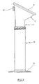
- the breast pump according to Fig. 1 to 4 has a cylindrical hollow piston 1, which is connected in one piece with a suction cup 2 at the upper end.
- the suction cup 2 is a hollow rotary body whose central axis is inclined at an acute angle to the central axis of the hollow cylinder 1.
- the suction bell 2 has a fluid passage 3 to the hollow piston. 1
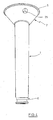
- the suction cup 2 has a substantially funnel-shaped shape. Its cross-section gradually widens starting from the fluid passage 3 to a large, circular opening 4 at the outer end. The opening 4 is surrounded by a bead 5. The shape of the suction cup 2 is bulged slightly outward with respect to a cone.
- the hollow piston 1 has at the lower end a recess in the form of a circumferential groove 6. Adjacent to the lower end of the hollow piston 1 has a portion of increased wall thickness 7, which receives the groove 6.
- the hollow piston 1 and the suction cup 2 are preferably made integrally from PP or PC or glass.
- a substantially funnel-shaped insert part 8 is inserted in the suction cup 2.
- the shape of the insert 8 can be described more accurately than trumpet-like.
- the insert 8 has a central through hole 9, to which a short cylindrical portion 10 is adjacent. From the cylindrical portion 10, a gradually expanding outward region 11 goes out. This has a bent-back edge 12, which is snapped over the edge bead 5 and thus fixed to this sealing.
- the insert 8 has a plurality of projecting nubs 13.
- the insert 8 is preferably made integrally from silicone rubber.
- a double lip sleeve 14 is arranged in the groove 6, .
- This has on an annular base body 15 which sits on the bottom of the groove 6, two circumferential lips 16, 17, which are inclined at an acute angle with respect to the annular base body 15 in different directions.
- the double-lip sleeve 14 is preferably made in one piece from silicone rubber.
- the hollow piston 1 is inserted into a cylinder 18, which has a slight oversize on the inside of the cylindrical surface of the hollow piston 1. The excess is chosen so that the hollow piston 1 is easily slidable within the cylinder 18, but is guided in the cylinder 18 so that it does not tilt therein.
- the two lips 16, 17 of the double lip sleeve 14 sealingly abut the inner wall of the cylinder 18.
- the cylinder 18 is closed at the bottom by a bottom 19.
- the floor 19 is part of a pedestal 20 projecting outwardly with respect to the cylinder 18.
- the cylinder 18 is preferably made in one piece from PP, PC or glass.
- the suction cup 2 carries a check valve 22. This is positioned on a cylindrical seat surface 23 of a sleeve-shaped projection 24 which is arranged on the outer surface of the suction cup 2 (see. Fig. 2 ).
- the projection 24 has a perforated bottom 25.
- the valve on a membrane has a valve body.
- the membrane is supported on the outside edge of the suction cup and the valve body is associated with a sealing seat in a through hole of the suction cup.
- valve body sits on the sealing seat and the through hole is closed. At overpressure diaphragm and valve body are deflected and the through hole opens.
- the lengths of the hollow piston 1 and the cylinder 18 are dimensioned so that the suction cup 2 protrudes beyond the upper edge of the cylinder 18 at least one thumb width when the hollow piston 1 is fully inserted into the cylinder 18, so that the lower end of the hollow piston 1 at the bottom 19 is present (see. Fig. 1 to 3 ).
- the soft elastic insert 8 is placed on the female breast.
- the user holds the hollow piston 1 between the suction cup 2 and the upper end of the cylinder 18 between thumb and forefinger firmly and pulls the cylinder 18 with the other hand down.
- milk flows into the cylinder 1.
- the double lip sleeve 14 ensures a high negative pressure during suction and prevents inflow of milk into the gap between the hollow piston 1 and cylinder 18.
- An overpressure during the pushing back of the cylinder 18 can escape through the check valve 22.
- backflowing breast milk can possibly pass through an annular gap 29 into the storage space 30 between the insert part 8 and the suction cup 2, so that contact with the mother's breast and leakage are avoided.
- the embodiment according to Fig. 5 and 6 differs from the above by a transparent cylinder 18, which makes it possible to observe the amount of milk sucked.
- the cylinder is provided in the vertical direction with a scale, not shown.
- the scale may have volume information.
- Fig. 7 differs from the above by the design of the insert 8 from.
- This insert 8 lacks the cylindrical portion 10, so that the small opening 9 is directly adjacent to the flared portion 11.
- This version without "fireplace” can with certain Applications be beneficial.
- no check valve 22 is present.
- Fig. 8 and 9 differs from the according to Fig. 5 and 6 in that at the lower end of the hollow piston 1 in a correspondingly shaped annular groove 6 ', an O-ring seal 14' is arranged.
- the suction cup 2 has no insert part 8 and the cylinder 18 has no external thread 21. In this very simple variant, however, the suction cup 2 is at least a thumb width beyond the cylinder 18 addition.
Landscapes
- Health & Medical Sciences (AREA)
- Heart & Thoracic Surgery (AREA)
- Animal Behavior & Ethology (AREA)
- General Health & Medical Sciences (AREA)
- Anesthesiology (AREA)
- Biomedical Technology (AREA)
- Hematology (AREA)
- Life Sciences & Earth Sciences (AREA)
- Vascular Medicine (AREA)
- Engineering & Computer Science (AREA)
- Public Health (AREA)
- Veterinary Medicine (AREA)
- Pediatric Medicine (AREA)
- External Artificial Organs (AREA)
- Details Of Reciprocating Pumps (AREA)
- Reciprocating Pumps (AREA)
Applications Claiming Priority (2)
| Application Number | Priority Date | Filing Date | Title |
|---|---|---|---|
| DE102006056321A DE102006056321B4 (de) | 2006-11-24 | 2006-11-24 | Manuelle Brustpumpe |
| PCT/EP2007/008501 WO2008061589A2 (de) | 2006-11-24 | 2007-09-29 | Manuelle brustpumpe |
Publications (2)
| Publication Number | Publication Date |
|---|---|
| EP2094329A2 EP2094329A2 (de) | 2009-09-02 |
| EP2094329B1 true EP2094329B1 (de) | 2014-02-26 |
Family
ID=39052757
Family Applications (1)
| Application Number | Title | Priority Date | Filing Date |
|---|---|---|---|
| EP07818581.6A Not-in-force EP2094329B1 (de) | 2006-11-24 | 2007-09-29 | Manuelle brustpumpe |
Country Status (15)
| Country | Link |
|---|---|
| US (1) | US20100049122A1 (pt) |
| EP (1) | EP2094329B1 (pt) |
| JP (1) | JP2010510007A (pt) |
| KR (1) | KR20090089884A (pt) |
| CN (1) | CN101600466B (pt) |
| AR (1) | AR063814A1 (pt) |
| AU (1) | AU2007323432A1 (pt) |
| BR (1) | BRPI0719143A2 (pt) |
| DE (1) | DE102006056321B4 (pt) |
| ES (1) | ES2460892T3 (pt) |
| MX (1) | MX2009005138A (pt) |
| RU (1) | RU2447903C2 (pt) |
| SA (1) | SA07280628B1 (pt) |
| WO (1) | WO2008061589A2 (pt) |
| ZA (1) | ZA200903316B (pt) |
Families Citing this family (25)
| Publication number | Priority date | Publication date | Assignee | Title |
|---|---|---|---|---|
| US20110306944A1 (en) * | 2010-06-14 | 2011-12-15 | Chean-Shui Chen | Milk collecting bottle for hand expression |
| EP2441480A1 (en) * | 2010-10-15 | 2012-04-18 | Koninklijke Philips Electronics N.V. | A funnel for a breast pump |
| EP2502639A1 (en) * | 2011-03-21 | 2012-09-26 | Koninklijke Philips Electronics N.V. | A breast pump |
| US9782526B2 (en) * | 2011-04-14 | 2017-10-10 | Maternal Life, Llc. | Device and method for collecting and dispensing colostrum |
| US8998879B2 (en) * | 2011-04-14 | 2015-04-07 | Maternal Life, Llc | Device and method for collecting and dispensing colostrum |
| US8979819B2 (en) * | 2011-04-14 | 2015-03-17 | Maternal Life, Llc | Device and method for collecting and dispensing colostrum |
| CN103394135B (zh) * | 2013-08-13 | 2015-08-19 | 陈俊波 | 一种吸奶器的吸乳罩结构 |
| US10080825B2 (en) | 2013-09-05 | 2018-09-25 | Lansinoh Laboratories, Inc. | Connector for collection and dispensing of breast milk or colostrum |
| US10426705B2 (en) | 2013-09-05 | 2019-10-01 | Lansinoh Laboratories, Inc. | Colostrum collection system |
| WO2015035224A1 (en) | 2013-09-05 | 2015-03-12 | Maternal Life, Llc | Connector for collection and dispensing of breast milk or colostrum |
| KR101546376B1 (ko) * | 2014-01-02 | 2015-08-21 | 주식회사 엠에스제이 | 착유기 |
| US11717599B2 (en) * | 2015-05-07 | 2023-08-08 | Babyation Inc. | Breast shield for a breast pump system |
| EP3208591A1 (en) * | 2016-02-17 | 2017-08-23 | Inficon GmbH | Vacuum bell probe and method for leak detection |
| DE102017119034A1 (de) * | 2017-08-21 | 2019-02-21 | Elisabeth Kurth | Babymundsimulator |
| JP7280667B2 (ja) * | 2018-06-05 | 2023-05-24 | ピジョン株式会社 | 搾乳器 |
| EP3597229A1 (de) * | 2018-07-17 | 2020-01-22 | Mam Babyartikel Gesellschaft m.b.H. | Elektrische brustpumpe |
| CN112638438B (zh) | 2018-09-06 | 2024-08-06 | 兰思诺实验室有限公司 | 用于吸乳器的振动波形 |
| WO2020051438A1 (en) | 2018-09-06 | 2020-03-12 | Lansinoh Laboratories, Inc. | Closed loop electric breast pump |
| WO2020051456A1 (en) | 2018-09-06 | 2020-03-12 | Lansinoh Laboratories, Inc. | Breast pumps |
| WO2021087107A1 (en) * | 2019-10-29 | 2021-05-06 | Acosta Medical Group, Inc. | Urine collection apparatuses |
| JP7433032B2 (ja) * | 2019-12-10 | 2024-02-19 | ピジョン株式会社 | 採乳補助具および採乳装置 |
| WO2022159245A1 (en) * | 2021-01-21 | 2022-07-28 | Turner Wayne D | Turner breast shield |
| US11759554B1 (en) * | 2021-01-21 | 2023-09-19 | Wayne D Turner | Breast shield with suckling motion one-way valve |
| US12521472B2 (en) * | 2022-08-17 | 2026-01-13 | Wayne D. Turner | Breast shield with suckling motion one way valve |
| CN119838074B (zh) * | 2025-03-20 | 2025-05-16 | 广东好女人母婴用品股份有限公司 | 一种基于动态自稳的负压防泄漏穿戴式吸奶器及使用方法 |
Family Cites Families (15)
| Publication number | Priority date | Publication date | Assignee | Title |
|---|---|---|---|---|
| DE836560C (de) * | 1948-10-14 | 1952-04-15 | Dr Med Georg Schaefer | Milchpumpe |
| FR1073552A (fr) * | 1953-01-26 | 1954-09-27 | Perfectionnements aux tire-lait | |
| FR1104570A (fr) * | 1954-05-14 | 1955-11-22 | Jouan Ets | Perfectionnements aux seringues |
| JPS5249918Y2 (pt) * | 1975-01-07 | 1977-11-12 | ||
| US3977405A (en) * | 1975-04-07 | 1976-08-31 | Shozaburo Yanase | Breast pump |
| EP0116186B1 (en) * | 1983-01-11 | 1986-07-23 | Ameda Ag | A manually operated breast pump |
| DE3419613A1 (de) * | 1984-05-25 | 1985-11-28 | Kirchner & Wilhelm, 7000 Stuttgart | Muttermilchabsaugvorrichtung |
| ATE64310T1 (de) * | 1986-02-28 | 1991-06-15 | Ameda Ag | Einsatzstueck fuer brustpumpen. |
| RU1630U1 (ru) * | 1994-03-04 | 1996-02-16 | Владимир Георгиевич Буланцов | Устройство для профилактики и лечения маститов |
| JP3744570B2 (ja) * | 1995-07-31 | 2006-02-15 | ピジョン株式会社 | 搾乳器 |
| US6110140A (en) * | 1996-09-17 | 2000-08-29 | Medela, Inc. | Manual breastmilk pump |
| EP0969886A4 (en) * | 1996-12-30 | 2000-08-30 | White River Concepts | MANUAL CHEST PUMP |
| JP2000152989A (ja) * | 1998-11-19 | 2000-06-06 | Bracco Internatl Bv | 注入器、カ―トリッジ及びそれらのプランジャリング |
| EP1184044B1 (de) * | 2000-08-28 | 2004-05-26 | Medela AG | Brusthaubeneinsatz |
| US20040127845A1 (en) * | 2002-12-27 | 2004-07-01 | Playtex Products, Inc. | Breast pump system |
-
2006
- 2006-11-24 DE DE102006056321A patent/DE102006056321B4/de not_active Expired - Fee Related
-
2007
- 2007-09-29 JP JP2009537496A patent/JP2010510007A/ja active Pending
- 2007-09-29 BR BRPI0719143-0A2A patent/BRPI0719143A2/pt not_active IP Right Cessation
- 2007-09-29 AU AU2007323432A patent/AU2007323432A1/en not_active Abandoned
- 2007-09-29 ES ES07818581.6T patent/ES2460892T3/es active Active
- 2007-09-29 EP EP07818581.6A patent/EP2094329B1/de not_active Not-in-force
- 2007-09-29 US US12/516,148 patent/US20100049122A1/en not_active Abandoned
- 2007-09-29 WO PCT/EP2007/008501 patent/WO2008061589A2/de not_active Ceased
- 2007-09-29 MX MX2009005138A patent/MX2009005138A/es unknown
- 2007-09-29 RU RU2009123989/14A patent/RU2447903C2/ru not_active IP Right Cessation
- 2007-09-29 KR KR1020097013169A patent/KR20090089884A/ko not_active Withdrawn
- 2007-09-29 CN CN2007800434013A patent/CN101600466B/zh not_active Expired - Fee Related
- 2007-11-14 AR ARP070105062A patent/AR063814A1/es unknown
- 2007-11-21 SA SA07280628A patent/SA07280628B1/ar unknown
-
2009
- 2009-05-13 ZA ZA200903316A patent/ZA200903316B/xx unknown
Also Published As
| Publication number | Publication date |
|---|---|
| BRPI0719143A2 (pt) | 2014-10-07 |
| CN101600466A (zh) | 2009-12-09 |
| DE102006056321B4 (de) | 2013-01-17 |
| AR063814A1 (es) | 2009-02-18 |
| WO2008061589A2 (de) | 2008-05-29 |
| RU2447903C2 (ru) | 2012-04-20 |
| JP2010510007A (ja) | 2010-04-02 |
| WO2008061589A3 (de) | 2008-07-31 |
| ES2460892T3 (es) | 2014-05-14 |
| AU2007323432A1 (en) | 2008-05-29 |
| MX2009005138A (es) | 2009-05-27 |
| KR20090089884A (ko) | 2009-08-24 |
| ZA200903316B (en) | 2009-12-30 |
| CN101600466B (zh) | 2012-04-04 |
| EP2094329A2 (de) | 2009-09-02 |
| SA07280628B1 (ar) | 2010-03-30 |
| DE102006056321A1 (de) | 2008-05-29 |
| RU2009123989A (ru) | 2010-12-27 |
| US20100049122A1 (en) | 2010-02-25 |
Similar Documents
| Publication | Publication Date | Title |
|---|---|---|
| EP2094329B1 (de) | Manuelle brustpumpe | |
| DE3731242C2 (pt) | ||
| EP3258981B1 (de) | Adapter mit medientrennmembran für eine brusthaube | |
| EP3329949B1 (de) | Brusthaubeneinheit | |
| DE69628608T3 (de) | Membrane-Brustpumpe | |
| DE69321819T2 (de) | Medizinische spülvorrichtung sowie verfahren | |
| DE20016859U1 (de) | Nasenspritze | |
| EP2536448A1 (de) | Kopplungsteil einer drainageschlaucheinheit | |
| EP2734250A1 (de) | Brusthaubeneinheit | |
| WO2016102698A1 (de) | Trinkbehälter mit einem trinkventil | |
| DE202011102157U1 (de) | Ein Aufbau eines Sprühkopfes | |
| DE69726616T2 (de) | Siphon-vorrichtung zum begiessen und abscheiden von flüssigkeit. | |
| DE102011008056B4 (de) | Umgedrehte Schaumspenderpumpe und Verfahren zum Nachrüsten einer Schaumspenderpumpe für umgedrehten Betrieb | |
| EP2708248A1 (de) | Manuelle Muttermilchpumpe | |
| AT413979B (de) | Trink-mundstück | |
| DE202014103535U1 (de) | Viehsäugvorrichtung | |
| EP1593401A1 (de) | Sauger für die Chirurgie | |
| EP1862604A2 (de) | Füllventil | |
| DE20022126U1 (de) | Sauger (Schnuller) | |
| DE69012679T2 (de) | Flüssigkeits-Durchflussventil für medizinische Instrumente. | |
| DE202006019416U1 (de) | Manuelle Brustpumpe | |
| DE19849271A1 (de) | Vorrichtung für eine zum Saugen eingerichtete Trinkflasche | |
| AT521888B1 (de) | Zahnärztliche Behandlungseinheit mit einem Saugstromventil | |
| DE102016215633B4 (de) | Melkbecherhülse und modulares Melkbecherhülsensystem | |
| EP1725196B1 (de) | Drainagebeutel |
Legal Events
| Date | Code | Title | Description |
|---|---|---|---|
| PUAI | Public reference made under article 153(3) epc to a published international application that has entered the european phase |
Free format text: ORIGINAL CODE: 0009012 |
|
| 17P | Request for examination filed |
Effective date: 20090623 |
|
| AK | Designated contracting states |
Kind code of ref document: A2 Designated state(s): AT BE BG CH CY CZ DE DK EE ES FI FR GB GR HU IE IS IT LI LT LU LV MC MT NL PL PT RO SE SI SK TR |
|
| DAX | Request for extension of the european patent (deleted) | ||
| RAP1 | Party data changed (applicant data changed or rights of an application transferred) |
Owner name: MAPA GMBH |
|
| 17Q | First examination report despatched |
Effective date: 20110519 |
|
| GRAP | Despatch of communication of intention to grant a patent |
Free format text: ORIGINAL CODE: EPIDOSNIGR1 |
|
| INTG | Intention to grant announced |
Effective date: 20131010 |
|
| GRAS | Grant fee paid |
Free format text: ORIGINAL CODE: EPIDOSNIGR3 |
|
| GRAA | (expected) grant |
Free format text: ORIGINAL CODE: 0009210 |
|
| AK | Designated contracting states |
Kind code of ref document: B1 Designated state(s): AT BE BG CH CY CZ DE DK EE ES FI FR GB GR HU IE IS IT LI LT LU LV MC MT NL PL PT RO SE SI SK TR |
|
| REG | Reference to a national code |
Ref country code: GB Ref legal event code: FG4D Free format text: NOT ENGLISH |
|
| REG | Reference to a national code |
Ref country code: CH Ref legal event code: EP |
|
| REG | Reference to a national code |
Ref country code: AT Ref legal event code: REF Ref document number: 653180 Country of ref document: AT Kind code of ref document: T Effective date: 20140315 |
|
| REG | Reference to a national code |
Ref country code: DE Ref legal event code: R096 Ref document number: 502007012792 Country of ref document: DE Effective date: 20140403 |
|
| REG | Reference to a national code |
Ref country code: IE Ref legal event code: FG4D Free format text: LANGUAGE OF EP DOCUMENT: GERMAN |
|
| REG | Reference to a national code |
Ref country code: ES Ref legal event code: FG2A Ref document number: 2460892 Country of ref document: ES Kind code of ref document: T3 Effective date: 20140514 |
|
| REG | Reference to a national code |
Ref country code: NL Ref legal event code: VDEP Effective date: 20140226 |
|
| REG | Reference to a national code |
Ref country code: LT Ref legal event code: MG4D |
|
| PG25 | Lapsed in a contracting state [announced via postgrant information from national office to epo] |
Ref country code: IS Free format text: LAPSE BECAUSE OF FAILURE TO SUBMIT A TRANSLATION OF THE DESCRIPTION OR TO PAY THE FEE WITHIN THE PRESCRIBED TIME-LIMIT Effective date: 20140626 Ref country code: LT Free format text: LAPSE BECAUSE OF FAILURE TO SUBMIT A TRANSLATION OF THE DESCRIPTION OR TO PAY THE FEE WITHIN THE PRESCRIBED TIME-LIMIT Effective date: 20140226 |
|
| PG25 | Lapsed in a contracting state [announced via postgrant information from national office to epo] |
Ref country code: FI Free format text: LAPSE BECAUSE OF FAILURE TO SUBMIT A TRANSLATION OF THE DESCRIPTION OR TO PAY THE FEE WITHIN THE PRESCRIBED TIME-LIMIT Effective date: 20140226 Ref country code: NL Free format text: LAPSE BECAUSE OF FAILURE TO SUBMIT A TRANSLATION OF THE DESCRIPTION OR TO PAY THE FEE WITHIN THE PRESCRIBED TIME-LIMIT Effective date: 20140226 Ref country code: PT Free format text: LAPSE BECAUSE OF FAILURE TO SUBMIT A TRANSLATION OF THE DESCRIPTION OR TO PAY THE FEE WITHIN THE PRESCRIBED TIME-LIMIT Effective date: 20140626 Ref country code: SE Free format text: LAPSE BECAUSE OF FAILURE TO SUBMIT A TRANSLATION OF THE DESCRIPTION OR TO PAY THE FEE WITHIN THE PRESCRIBED TIME-LIMIT Effective date: 20140226 Ref country code: CY Free format text: LAPSE BECAUSE OF FAILURE TO SUBMIT A TRANSLATION OF THE DESCRIPTION OR TO PAY THE FEE WITHIN THE PRESCRIBED TIME-LIMIT Effective date: 20140226 |
|
| PG25 | Lapsed in a contracting state [announced via postgrant information from national office to epo] |
Ref country code: LV Free format text: LAPSE BECAUSE OF FAILURE TO SUBMIT A TRANSLATION OF THE DESCRIPTION OR TO PAY THE FEE WITHIN THE PRESCRIBED TIME-LIMIT Effective date: 20140226 |
|
| PG25 | Lapsed in a contracting state [announced via postgrant information from national office to epo] |
Ref country code: CZ Free format text: LAPSE BECAUSE OF FAILURE TO SUBMIT A TRANSLATION OF THE DESCRIPTION OR TO PAY THE FEE WITHIN THE PRESCRIBED TIME-LIMIT Effective date: 20140226 Ref country code: EE Free format text: LAPSE BECAUSE OF FAILURE TO SUBMIT A TRANSLATION OF THE DESCRIPTION OR TO PAY THE FEE WITHIN THE PRESCRIBED TIME-LIMIT Effective date: 20140226 Ref country code: RO Free format text: LAPSE BECAUSE OF FAILURE TO SUBMIT A TRANSLATION OF THE DESCRIPTION OR TO PAY THE FEE WITHIN THE PRESCRIBED TIME-LIMIT Effective date: 20140226 Ref country code: DK Free format text: LAPSE BECAUSE OF FAILURE TO SUBMIT A TRANSLATION OF THE DESCRIPTION OR TO PAY THE FEE WITHIN THE PRESCRIBED TIME-LIMIT Effective date: 20140226 |
|
| REG | Reference to a national code |
Ref country code: DE Ref legal event code: R097 Ref document number: 502007012792 Country of ref document: DE |
|
| PG25 | Lapsed in a contracting state [announced via postgrant information from national office to epo] |
Ref country code: PL Free format text: LAPSE BECAUSE OF FAILURE TO SUBMIT A TRANSLATION OF THE DESCRIPTION OR TO PAY THE FEE WITHIN THE PRESCRIBED TIME-LIMIT Effective date: 20140226 Ref country code: SK Free format text: LAPSE BECAUSE OF FAILURE TO SUBMIT A TRANSLATION OF THE DESCRIPTION OR TO PAY THE FEE WITHIN THE PRESCRIBED TIME-LIMIT Effective date: 20140226 |
|
| PLBE | No opposition filed within time limit |
Free format text: ORIGINAL CODE: 0009261 |
|
| STAA | Information on the status of an ep patent application or granted ep patent |
Free format text: STATUS: NO OPPOSITION FILED WITHIN TIME LIMIT |
|
| 26N | No opposition filed |
Effective date: 20141127 |
|
| REG | Reference to a national code |
Ref country code: DE Ref legal event code: R097 Ref document number: 502007012792 Country of ref document: DE Effective date: 20141127 |
|
| PG25 | Lapsed in a contracting state [announced via postgrant information from national office to epo] |
Ref country code: LU Free format text: LAPSE BECAUSE OF FAILURE TO SUBMIT A TRANSLATION OF THE DESCRIPTION OR TO PAY THE FEE WITHIN THE PRESCRIBED TIME-LIMIT Effective date: 20140929 Ref country code: MC Free format text: LAPSE BECAUSE OF FAILURE TO SUBMIT A TRANSLATION OF THE DESCRIPTION OR TO PAY THE FEE WITHIN THE PRESCRIBED TIME-LIMIT Effective date: 20140226 |
|
| REG | Reference to a national code |
Ref country code: CH Ref legal event code: PL |
|
| GBPC | Gb: european patent ceased through non-payment of renewal fee |
Effective date: 20140929 |
|
| PG25 | Lapsed in a contracting state [announced via postgrant information from national office to epo] |
Ref country code: SI Free format text: LAPSE BECAUSE OF FAILURE TO SUBMIT A TRANSLATION OF THE DESCRIPTION OR TO PAY THE FEE WITHIN THE PRESCRIBED TIME-LIMIT Effective date: 20140226 |
|
| REG | Reference to a national code |
Ref country code: FR Ref legal event code: ST Effective date: 20150529 |
|
| PG25 | Lapsed in a contracting state [announced via postgrant information from national office to epo] |
Ref country code: BE Free format text: LAPSE BECAUSE OF NON-PAYMENT OF DUE FEES Effective date: 20140930 |
|
| REG | Reference to a national code |
Ref country code: IE Ref legal event code: MM4A |
|
| PG25 | Lapsed in a contracting state [announced via postgrant information from national office to epo] |
Ref country code: GB Free format text: LAPSE BECAUSE OF NON-PAYMENT OF DUE FEES Effective date: 20140929 Ref country code: LI Free format text: LAPSE BECAUSE OF NON-PAYMENT OF DUE FEES Effective date: 20140930 Ref country code: CH Free format text: LAPSE BECAUSE OF NON-PAYMENT OF DUE FEES Effective date: 20140930 |
|
| PG25 | Lapsed in a contracting state [announced via postgrant information from national office to epo] |
Ref country code: FR Free format text: LAPSE BECAUSE OF NON-PAYMENT OF DUE FEES Effective date: 20140930 Ref country code: IE Free format text: LAPSE BECAUSE OF NON-PAYMENT OF DUE FEES Effective date: 20140929 Ref country code: IT Free format text: LAPSE BECAUSE OF NON-PAYMENT OF DUE FEES Effective date: 20140929 |
|
| REG | Reference to a national code |
Ref country code: AT Ref legal event code: MM01 Ref document number: 653180 Country of ref document: AT Kind code of ref document: T Effective date: 20140929 |
|
| PGFP | Annual fee paid to national office [announced via postgrant information from national office to epo] |
Ref country code: DE Payment date: 20151113 Year of fee payment: 9 |
|
| REG | Reference to a national code |
Ref country code: ES Ref legal event code: FD2A Effective date: 20160205 |
|
| PG25 | Lapsed in a contracting state [announced via postgrant information from national office to epo] |
Ref country code: AT Free format text: LAPSE BECAUSE OF NON-PAYMENT OF DUE FEES Effective date: 20140929 |
|
| PG25 | Lapsed in a contracting state [announced via postgrant information from national office to epo] |
Ref country code: ES Free format text: LAPSE BECAUSE OF NON-PAYMENT OF DUE FEES Effective date: 20140930 |
|
| PG25 | Lapsed in a contracting state [announced via postgrant information from national office to epo] |
Ref country code: BG Free format text: LAPSE BECAUSE OF FAILURE TO SUBMIT A TRANSLATION OF THE DESCRIPTION OR TO PAY THE FEE WITHIN THE PRESCRIBED TIME-LIMIT Effective date: 20140226 |
|
| PG25 | Lapsed in a contracting state [announced via postgrant information from national office to epo] |
Ref country code: MT Free format text: LAPSE BECAUSE OF FAILURE TO SUBMIT A TRANSLATION OF THE DESCRIPTION OR TO PAY THE FEE WITHIN THE PRESCRIBED TIME-LIMIT Effective date: 20140226 Ref country code: GR Free format text: LAPSE BECAUSE OF FAILURE TO SUBMIT A TRANSLATION OF THE DESCRIPTION OR TO PAY THE FEE WITHIN THE PRESCRIBED TIME-LIMIT Effective date: 20140527 |
|
| PG25 | Lapsed in a contracting state [announced via postgrant information from national office to epo] |
Ref country code: HU Free format text: LAPSE BECAUSE OF FAILURE TO SUBMIT A TRANSLATION OF THE DESCRIPTION OR TO PAY THE FEE WITHIN THE PRESCRIBED TIME-LIMIT; INVALID AB INITIO Effective date: 20070929 Ref country code: TR Free format text: LAPSE BECAUSE OF FAILURE TO SUBMIT A TRANSLATION OF THE DESCRIPTION OR TO PAY THE FEE WITHIN THE PRESCRIBED TIME-LIMIT Effective date: 20140226 |
|
| REG | Reference to a national code |
Ref country code: DE Ref legal event code: R119 Ref document number: 502007012792 Country of ref document: DE |
|
| PG25 | Lapsed in a contracting state [announced via postgrant information from national office to epo] |
Ref country code: DE Free format text: LAPSE BECAUSE OF NON-PAYMENT OF DUE FEES Effective date: 20170401 |