EP2094404B1 - Verfahren und vorrichtung zur behandlung einer oberfläche - Google Patents
Verfahren und vorrichtung zur behandlung einer oberfläche Download PDFInfo
- Publication number
- EP2094404B1 EP2094404B1 EP07824454A EP07824454A EP2094404B1 EP 2094404 B1 EP2094404 B1 EP 2094404B1 EP 07824454 A EP07824454 A EP 07824454A EP 07824454 A EP07824454 A EP 07824454A EP 2094404 B1 EP2094404 B1 EP 2094404B1
- Authority
- EP
- European Patent Office
- Prior art keywords
- surface treatment
- article
- treatment medium
- seal
- absorbent member
- Prior art date
- Legal status (The legal status is an assumption and is not a legal conclusion. Google has not performed a legal analysis and makes no representation as to the accuracy of the status listed.)
- Not-in-force
Links
- 238000000034 method Methods 0.000 title claims description 33
- 230000002745 absorbent Effects 0.000 claims abstract description 104
- 239000002250 absorbent Substances 0.000 claims abstract description 104
- 238000004381 surface treatment Methods 0.000 claims abstract description 91
- 238000007789 sealing Methods 0.000 claims abstract description 19
- 230000000694 effects Effects 0.000 claims description 7
- 230000003068 static effect Effects 0.000 claims description 2
- 230000015572 biosynthetic process Effects 0.000 abstract description 3
- 238000010438 heat treatment Methods 0.000 description 44
- 239000000463 material Substances 0.000 description 44
- 239000000758 substrate Substances 0.000 description 34
- 238000004140 cleaning Methods 0.000 description 26
- 239000000356 contaminant Substances 0.000 description 23
- 239000012459 cleaning agent Substances 0.000 description 21
- 239000004411 aluminium Substances 0.000 description 19
- 229910052782 aluminium Inorganic materials 0.000 description 19
- XAGFODPZIPBFFR-UHFFFAOYSA-N aluminium Chemical compound [Al] XAGFODPZIPBFFR-UHFFFAOYSA-N 0.000 description 17
- -1 wool Polymers 0.000 description 15
- 239000000243 solution Substances 0.000 description 14
- 239000000126 substance Substances 0.000 description 13
- 239000002904 solvent Substances 0.000 description 12
- 239000001913 cellulose Substances 0.000 description 11
- 229920002678 cellulose Polymers 0.000 description 11
- 229930195733 hydrocarbon Natural products 0.000 description 11
- 229920000642 polymer Polymers 0.000 description 11
- 239000000835 fiber Substances 0.000 description 10
- 238000004833 X-ray photoelectron spectroscopy Methods 0.000 description 9
- 239000000919 ceramic Substances 0.000 description 9
- 238000001816 cooling Methods 0.000 description 9
- 150000002430 hydrocarbons Chemical class 0.000 description 9
- 150000002484 inorganic compounds Chemical class 0.000 description 9
- 150000002894 organic compounds Chemical class 0.000 description 9
- 239000004753 textile Substances 0.000 description 9
- 239000004215 Carbon black (E152) Substances 0.000 description 8
- 229910052751 metal Inorganic materials 0.000 description 8
- 239000002184 metal Substances 0.000 description 8
- 239000000203 mixture Substances 0.000 description 8
- 150000002148 esters Chemical class 0.000 description 7
- LYCAIKOWRPUZTN-UHFFFAOYSA-N ethylene glycol Natural products OCCO LYCAIKOWRPUZTN-UHFFFAOYSA-N 0.000 description 7
- 239000011521 glass Substances 0.000 description 7
- 239000003880 polar aprotic solvent Substances 0.000 description 7
- 239000004094 surface-active agent Substances 0.000 description 7
- 239000004135 Bone phosphate Chemical class 0.000 description 6
- OKTJSMMVPCPJKN-UHFFFAOYSA-N Carbon Chemical compound [C] OKTJSMMVPCPJKN-UHFFFAOYSA-N 0.000 description 6
- CDBYLPFSWZWCQE-UHFFFAOYSA-L Sodium Carbonate Chemical compound [Na+].[Na+].[O-]C([O-])=O CDBYLPFSWZWCQE-UHFFFAOYSA-L 0.000 description 6
- 150000001298 alcohols Chemical class 0.000 description 6
- 229910052799 carbon Inorganic materials 0.000 description 6
- 230000002255 enzymatic effect Effects 0.000 description 6
- 150000002334 glycols Chemical class 0.000 description 6
- WGCNASOHLSPBMP-UHFFFAOYSA-N hydroxyacetaldehyde Natural products OCC=O WGCNASOHLSPBMP-UHFFFAOYSA-N 0.000 description 6
- 239000002608 ionic liquid Substances 0.000 description 6
- 150000002576 ketones Chemical class 0.000 description 6
- 239000007788 liquid Substances 0.000 description 6
- 239000007864 aqueous solution Substances 0.000 description 5
- 230000008901 benefit Effects 0.000 description 5
- 150000005676 cyclic carbonates Chemical class 0.000 description 5
- 239000008367 deionised water Substances 0.000 description 5
- 229920001971 elastomer Polymers 0.000 description 5
- 150000002739 metals Chemical class 0.000 description 5
- 229920001721 polyimide Polymers 0.000 description 5
- 239000000843 powder Substances 0.000 description 5
- XLYOFNOQVPJJNP-UHFFFAOYSA-N water Substances O XLYOFNOQVPJJNP-UHFFFAOYSA-N 0.000 description 5
- XMGQYMWWDOXHJM-JTQLQIEISA-N (+)-α-limonene Chemical compound CC(=C)[C@@H]1CCC(C)=CC1 XMGQYMWWDOXHJM-JTQLQIEISA-N 0.000 description 4
- YEJRWHAVMIAJKC-UHFFFAOYSA-N 4-Butyrolactone Chemical compound O=C1CCCO1 YEJRWHAVMIAJKC-UHFFFAOYSA-N 0.000 description 4
- IJGRMHOSHXDMSA-UHFFFAOYSA-N Atomic nitrogen Chemical compound N#N IJGRMHOSHXDMSA-UHFFFAOYSA-N 0.000 description 4
- 229920002472 Starch Polymers 0.000 description 4
- 239000003599 detergent Substances 0.000 description 4
- 229910010272 inorganic material Inorganic materials 0.000 description 4
- 229910052500 inorganic mineral Inorganic materials 0.000 description 4
- 239000011707 mineral Substances 0.000 description 4
- 229920002635 polyurethane Polymers 0.000 description 4
- 239000004814 polyurethane Substances 0.000 description 4
- 239000004065 semiconductor Substances 0.000 description 4
- 239000008107 starch Substances 0.000 description 4
- 235000019698 starch Nutrition 0.000 description 4
- MHAJPDPJQMAIIY-UHFFFAOYSA-N Hydrogen peroxide Chemical compound OO MHAJPDPJQMAIIY-UHFFFAOYSA-N 0.000 description 3
- FYYHWMGAXLPEAU-UHFFFAOYSA-N Magnesium Chemical compound [Mg] FYYHWMGAXLPEAU-UHFFFAOYSA-N 0.000 description 3
- 229910021536 Zeolite Inorganic materials 0.000 description 3
- QVGXLLKOCUKJST-UHFFFAOYSA-N atomic oxygen Chemical compound [O] QVGXLLKOCUKJST-UHFFFAOYSA-N 0.000 description 3
- 238000011109 contamination Methods 0.000 description 3
- MTHSVFCYNBDYFN-UHFFFAOYSA-N diethylene glycol Chemical compound OCCOCCO MTHSVFCYNBDYFN-UHFFFAOYSA-N 0.000 description 3
- HNPSIPDUKPIQMN-UHFFFAOYSA-N dioxosilane;oxo(oxoalumanyloxy)alumane Chemical compound O=[Si]=O.O=[Al]O[Al]=O HNPSIPDUKPIQMN-UHFFFAOYSA-N 0.000 description 3
- LZCLXQDLBQLTDK-UHFFFAOYSA-N ethyl 2-hydroxypropanoate Chemical compound CCOC(=O)C(C)O LZCLXQDLBQLTDK-UHFFFAOYSA-N 0.000 description 3
- 239000003925 fat Substances 0.000 description 3
- 239000012530 fluid Substances 0.000 description 3
- 229920002313 fluoropolymer Polymers 0.000 description 3
- 239000011888 foil Substances 0.000 description 3
- 238000009472 formulation Methods 0.000 description 3
- 239000003365 glass fiber Substances 0.000 description 3
- 239000011777 magnesium Substances 0.000 description 3
- 229910052749 magnesium Inorganic materials 0.000 description 3
- 238000004519 manufacturing process Methods 0.000 description 3
- 239000011490 mineral wool Substances 0.000 description 3
- 239000012457 nonaqueous media Substances 0.000 description 3
- 239000001301 oxygen Substances 0.000 description 3
- 229910052760 oxygen Inorganic materials 0.000 description 3
- 229920000728 polyester Polymers 0.000 description 3
- 229920000098 polyolefin Polymers 0.000 description 3
- 230000008569 process Effects 0.000 description 3
- 229910000029 sodium carbonate Inorganic materials 0.000 description 3
- 229920002994 synthetic fiber Polymers 0.000 description 3
- 239000000454 talc Substances 0.000 description 3
- 229910052623 talc Inorganic materials 0.000 description 3
- 238000005406 washing Methods 0.000 description 3
- 210000002268 wool Anatomy 0.000 description 3
- 239000010457 zeolite Substances 0.000 description 3
- OAYXUHPQHDHDDZ-UHFFFAOYSA-N 2-(2-butoxyethoxy)ethanol Chemical compound CCCCOCCOCCO OAYXUHPQHDHDDZ-UHFFFAOYSA-N 0.000 description 2
- DKPFZGUDAPQIHT-UHFFFAOYSA-N Butyl acetate Natural products CCCCOC(C)=O DKPFZGUDAPQIHT-UHFFFAOYSA-N 0.000 description 2
- 108010059892 Cellulase Proteins 0.000 description 2
- MUXOBHXGJLMRAB-UHFFFAOYSA-N Dimethyl succinate Chemical compound COC(=O)CCC(=O)OC MUXOBHXGJLMRAB-UHFFFAOYSA-N 0.000 description 2
- IAZDPXIOMUYVGZ-UHFFFAOYSA-N Dimethylsulphoxide Chemical compound CS(C)=O IAZDPXIOMUYVGZ-UHFFFAOYSA-N 0.000 description 2
- YCKRFDGAMUMZLT-UHFFFAOYSA-N Fluorine atom Chemical compound [F] YCKRFDGAMUMZLT-UHFFFAOYSA-N 0.000 description 2
- 102000004882 Lipase Human genes 0.000 description 2
- 239000004367 Lipase Substances 0.000 description 2
- 108090001060 Lipase Proteins 0.000 description 2
- SECXISVLQFMRJM-UHFFFAOYSA-N N-Methylpyrrolidone Chemical compound CN1CCCC1=O SECXISVLQFMRJM-UHFFFAOYSA-N 0.000 description 2
- 239000004677 Nylon Substances 0.000 description 2
- 108091005804 Peptidases Proteins 0.000 description 2
- OAICVXFJPJFONN-UHFFFAOYSA-N Phosphorus Chemical compound [P] OAICVXFJPJFONN-UHFFFAOYSA-N 0.000 description 2
- 239000004642 Polyimide Substances 0.000 description 2
- 229920005830 Polyurethane Foam Polymers 0.000 description 2
- 239000004365 Protease Substances 0.000 description 2
- 102100037486 Reverse transcriptase/ribonuclease H Human genes 0.000 description 2
- XUIMIQQOPSSXEZ-UHFFFAOYSA-N Silicon Chemical compound [Si] XUIMIQQOPSSXEZ-UHFFFAOYSA-N 0.000 description 2
- 239000005708 Sodium hypochlorite Substances 0.000 description 2
- 241000191967 Staphylococcus aureus Species 0.000 description 2
- 229910000831 Steel Inorganic materials 0.000 description 2
- DOOTYTYQINUNNV-UHFFFAOYSA-N Triethyl citrate Chemical compound CCOC(=O)CC(O)(C(=O)OCC)CC(=O)OCC DOOTYTYQINUNNV-UHFFFAOYSA-N 0.000 description 2
- 239000000853 adhesive Substances 0.000 description 2
- 230000001070 adhesive effect Effects 0.000 description 2
- 238000007605 air drying Methods 0.000 description 2
- 239000002280 amphoteric surfactant Substances 0.000 description 2
- 238000004458 analytical method Methods 0.000 description 2
- 125000000129 anionic group Chemical group 0.000 description 2
- 239000003125 aqueous solvent Substances 0.000 description 2
- 229920001400 block copolymer Polymers 0.000 description 2
- 125000002091 cationic group Chemical group 0.000 description 2
- 229940106157 cellulase Drugs 0.000 description 2
- 239000003795 chemical substances by application Substances 0.000 description 2
- 230000000052 comparative effect Effects 0.000 description 2
- 229940028356 diethylene glycol monobutyl ether Drugs 0.000 description 2
- 229960001760 dimethyl sulfoxide Drugs 0.000 description 2
- 239000000975 dye Substances 0.000 description 2
- 239000000806 elastomer Substances 0.000 description 2
- 238000005516 engineering process Methods 0.000 description 2
- 229940116333 ethyl lactate Drugs 0.000 description 2
- 229910052731 fluorine Inorganic materials 0.000 description 2
- 239000011737 fluorine Substances 0.000 description 2
- 230000004907 flux Effects 0.000 description 2
- 239000002529 flux (metallurgy) Substances 0.000 description 2
- 239000006260 foam Substances 0.000 description 2
- FUZZWVXGSFPDMH-UHFFFAOYSA-M hexanoate Chemical compound CCCCCC([O-])=O FUZZWVXGSFPDMH-UHFFFAOYSA-M 0.000 description 2
- 235000019421 lipase Nutrition 0.000 description 2
- 235000013336 milk Nutrition 0.000 description 2
- 239000008267 milk Substances 0.000 description 2
- 210000004080 milk Anatomy 0.000 description 2
- 229910052757 nitrogen Inorganic materials 0.000 description 2
- 229920001778 nylon Polymers 0.000 description 2
- 239000003921 oil Substances 0.000 description 2
- JCGNDDUYTRNOFT-UHFFFAOYSA-N oxolane-2,4-dione Chemical compound O=C1COC(=O)C1 JCGNDDUYTRNOFT-UHFFFAOYSA-N 0.000 description 2
- 239000000123 paper Substances 0.000 description 2
- 229910052698 phosphorus Inorganic materials 0.000 description 2
- 239000011574 phosphorus Substances 0.000 description 2
- 229920003223 poly(pyromellitimide-1,4-diphenyl ether) Polymers 0.000 description 2
- 229920005644 polyethylene terephthalate glycol copolymer Polymers 0.000 description 2
- 229920006254 polymer film Polymers 0.000 description 2
- 239000011496 polyurethane foam Substances 0.000 description 2
- 239000011347 resin Substances 0.000 description 2
- 229920005989 resin Polymers 0.000 description 2
- 239000010703 silicon Substances 0.000 description 2
- 229910052710 silicon Inorganic materials 0.000 description 2
- SUKJFIGYRHOWBL-UHFFFAOYSA-N sodium hypochlorite Chemical compound [Na+].Cl[O-] SUKJFIGYRHOWBL-UHFFFAOYSA-N 0.000 description 2
- 239000002689 soil Substances 0.000 description 2
- 241000894007 species Species 0.000 description 2
- 239000010959 steel Substances 0.000 description 2
- 239000001069 triethyl citrate Substances 0.000 description 2
- VMYFZRTXGLUXMZ-UHFFFAOYSA-N triethyl citrate Natural products CCOC(=O)C(O)(C(=O)OCC)C(=O)OCC VMYFZRTXGLUXMZ-UHFFFAOYSA-N 0.000 description 2
- 235000013769 triethyl citrate Nutrition 0.000 description 2
- 239000002966 varnish Substances 0.000 description 2
- 229910052725 zinc Inorganic materials 0.000 description 2
- 239000011701 zinc Substances 0.000 description 2
- DURPTKYDGMDSBL-UHFFFAOYSA-N 1-butoxybutane Chemical compound CCCCOCCCC DURPTKYDGMDSBL-UHFFFAOYSA-N 0.000 description 1
- NJMWOUFKYKNWDW-UHFFFAOYSA-N 1-ethyl-3-methylimidazolium Chemical compound CCN1C=C[N+](C)=C1 NJMWOUFKYKNWDW-UHFFFAOYSA-N 0.000 description 1
- 229920004439 Aclar® Polymers 0.000 description 1
- 229910001339 C alloy Inorganic materials 0.000 description 1
- 239000004593 Epoxy Substances 0.000 description 1
- JOYRKODLDBILNP-UHFFFAOYSA-N Ethyl urethane Chemical compound CCOC(N)=O JOYRKODLDBILNP-UHFFFAOYSA-N 0.000 description 1
- CWYNVVGOOAEACU-UHFFFAOYSA-N Fe2+ Chemical compound [Fe+2] CWYNVVGOOAEACU-UHFFFAOYSA-N 0.000 description 1
- UFHFLCQGNIYNRP-UHFFFAOYSA-N Hydrogen Chemical compound [H][H] UFHFLCQGNIYNRP-UHFFFAOYSA-N 0.000 description 1
- RAXXELZNTBOGNW-UHFFFAOYSA-O Imidazolium Chemical compound C1=C[NH+]=CN1 RAXXELZNTBOGNW-UHFFFAOYSA-O 0.000 description 1
- 229920000459 Nitrile rubber Polymers 0.000 description 1
- 239000004698 Polyethylene Substances 0.000 description 1
- 239000004743 Polypropylene Substances 0.000 description 1
- 229920000297 Rayon Polymers 0.000 description 1
- NINIDFKCEFEMDL-UHFFFAOYSA-N Sulfur Chemical compound [S] NINIDFKCEFEMDL-UHFFFAOYSA-N 0.000 description 1
- 239000005864 Sulphur Substances 0.000 description 1
- FEWJPZIEWOKRBE-UHFFFAOYSA-N Tartaric acid Natural products [H+].[H+].[O-]C(=O)C(O)C(O)C([O-])=O FEWJPZIEWOKRBE-UHFFFAOYSA-N 0.000 description 1
- 229910001069 Ti alloy Inorganic materials 0.000 description 1
- XSTXAVWGXDQKEL-UHFFFAOYSA-N Trichloroethylene Chemical group ClC=C(Cl)Cl XSTXAVWGXDQKEL-UHFFFAOYSA-N 0.000 description 1
- HCHKCACWOHOZIP-UHFFFAOYSA-N Zinc Chemical compound [Zn] HCHKCACWOHOZIP-UHFFFAOYSA-N 0.000 description 1
- 150000001398 aluminium Chemical class 0.000 description 1
- 239000005030 aluminium foil Substances 0.000 description 1
- REDXJYDRNCIFBQ-UHFFFAOYSA-N aluminium(3+) Chemical compound [Al+3] REDXJYDRNCIFBQ-UHFFFAOYSA-N 0.000 description 1
- 230000000844 anti-bacterial effect Effects 0.000 description 1
- 239000012298 atmosphere Substances 0.000 description 1
- 230000001580 bacterial effect Effects 0.000 description 1
- 230000004888 barrier function Effects 0.000 description 1
- 238000009835 boiling Methods 0.000 description 1
- 229910010293 ceramic material Inorganic materials 0.000 description 1
- 239000000460 chlorine Substances 0.000 description 1
- 229910052801 chlorine Inorganic materials 0.000 description 1
- 239000011538 cleaning material Substances 0.000 description 1
- 239000011248 coating agent Substances 0.000 description 1
- 238000000576 coating method Methods 0.000 description 1
- 238000010276 construction Methods 0.000 description 1
- 230000003247 decreasing effect Effects 0.000 description 1
- 230000001419 dependent effect Effects 0.000 description 1
- 235000014113 dietary fatty acids Nutrition 0.000 description 1
- 238000009826 distribution Methods 0.000 description 1
- 230000005611 electricity Effects 0.000 description 1
- 238000009713 electroplating Methods 0.000 description 1
- 150000002170 ethers Chemical class 0.000 description 1
- 238000001704 evaporation Methods 0.000 description 1
- 230000008020 evaporation Effects 0.000 description 1
- 239000004744 fabric Substances 0.000 description 1
- 239000000194 fatty acid Substances 0.000 description 1
- 229930195729 fatty acid Natural products 0.000 description 1
- 150000004665 fatty acids Chemical class 0.000 description 1
- 229920001973 fluoroelastomer Polymers 0.000 description 1
- 239000004811 fluoropolymer Substances 0.000 description 1
- 239000001307 helium Substances 0.000 description 1
- 229910052734 helium Inorganic materials 0.000 description 1
- SWQJXJOGLNCZEY-UHFFFAOYSA-N helium atom Chemical compound [He] SWQJXJOGLNCZEY-UHFFFAOYSA-N 0.000 description 1
- 125000001183 hydrocarbyl group Chemical group 0.000 description 1
- 239000001257 hydrogen Substances 0.000 description 1
- 229910052739 hydrogen Inorganic materials 0.000 description 1
- 239000000976 ink Substances 0.000 description 1
- 239000011810 insulating material Substances 0.000 description 1
- 238000009413 insulation Methods 0.000 description 1
- 239000004922 lacquer Substances 0.000 description 1
- 229910052747 lanthanoid Inorganic materials 0.000 description 1
- 150000002602 lanthanoids Chemical class 0.000 description 1
- 229910001234 light alloy Inorganic materials 0.000 description 1
- 238000010297 mechanical methods and process Methods 0.000 description 1
- 238000002844 melting Methods 0.000 description 1
- 230000008018 melting Effects 0.000 description 1
- 230000000813 microbial effect Effects 0.000 description 1
- 238000012986 modification Methods 0.000 description 1
- 230000004048 modification Effects 0.000 description 1
- 239000000025 natural resin Substances 0.000 description 1
- 239000003960 organic solvent Substances 0.000 description 1
- 239000003973 paint Substances 0.000 description 1
- 239000005023 polychlorotrifluoroethylene (PCTFE) polymer Substances 0.000 description 1
- 229920000573 polyethylene Polymers 0.000 description 1
- 229920001155 polypropylene Polymers 0.000 description 1
- 229920001296 polysiloxane Polymers 0.000 description 1
- 238000007639 printing Methods 0.000 description 1
- 230000002035 prolonged effect Effects 0.000 description 1
- RUOJZAUFBMNUDX-UHFFFAOYSA-N propylene carbonate Chemical compound CC1COC(=O)O1 RUOJZAUFBMNUDX-UHFFFAOYSA-N 0.000 description 1
- 102000004169 proteins and genes Human genes 0.000 description 1
- 108090000623 proteins and genes Proteins 0.000 description 1
- 238000005488 sandblasting Methods 0.000 description 1
- 238000007790 scraping Methods 0.000 description 1
- 239000003566 sealing material Substances 0.000 description 1
- 229920002379 silicone rubber Polymers 0.000 description 1
- 239000004945 silicone rubber Substances 0.000 description 1
- 239000000344 soap Substances 0.000 description 1
- 239000008149 soap solution Substances 0.000 description 1
- 238000001228 spectrum Methods 0.000 description 1
- 229910001220 stainless steel Inorganic materials 0.000 description 1
- 239000010935 stainless steel Substances 0.000 description 1
- 238000005211 surface analysis Methods 0.000 description 1
- 239000000725 suspension Substances 0.000 description 1
- 235000002906 tartaric acid Nutrition 0.000 description 1
- 239000011975 tartaric acid Substances 0.000 description 1
- 229920002725 thermoplastic elastomer Polymers 0.000 description 1
- UBOXGVDOUJQMTN-UHFFFAOYSA-N trichloroethylene Natural products ClCC(Cl)Cl UBOXGVDOUJQMTN-UHFFFAOYSA-N 0.000 description 1
- 125000000391 vinyl group Chemical group [H]C([*])=C([H])[H] 0.000 description 1
- 229920002554 vinyl polymer Polymers 0.000 description 1
- 239000002699 waste material Substances 0.000 description 1
- 239000002023 wood Substances 0.000 description 1
Images




Classifications
-
- A—HUMAN NECESSITIES
- A47—FURNITURE; DOMESTIC ARTICLES OR APPLIANCES; COFFEE MILLS; SPICE MILLS; SUCTION CLEANERS IN GENERAL
- A47L—DOMESTIC WASHING OR CLEANING; SUCTION CLEANERS IN GENERAL
- A47L13/00—Implements for cleaning floors, carpets, furniture, walls, or wall coverings
- A47L13/10—Scrubbing; Scouring; Cleaning; Polishing
- A47L13/16—Cloths; Pads; Sponges
- A47L13/17—Cloths; Pads; Sponges containing cleaning agents
Definitions
- This invention relates to methods and apparatus for treating surfaces. More particularly, but not exclusively, this invention relates to methods and apparatus for removing contaminants from surfaces.
- Patent specification No. US 4336073 discloses a glass cleaning process and apparatus.
- a method of treating a surface of an article with a surface treatment medium comprising: providing a surface treatment apparatus comprising an absorbent member for holding the surface treatment medium, said absorbent member having a facing portion to contact the surface, a mounting member defining a recess to receive the absorbent member, wherein the mounting member has a sealing arrangement to provide a seal extending around the absorbent member; allowing the absorbent member to hold the surface treatment medium; effecting contact between the surface treatment medium and the surface for a sufficient period of time to effect the treatment of the surface; characterised in that the method further includes effecting engagement of the sealing arrangement either with the article or with a further component of the apparatus to form a seal against either said article or said further component to prevent leakage of the surface treatment medium from the apparatus.
- a surface treatment apparatus for treating a surface of an article with a surface treatment medium
- the apparatus comprising: an absorbent member to hold the surface treatment medium, the absorbent member having a facing portion to contact the surface; a mounting member defining a recess to receive the absorbent member, wherein the mounting member comprises a main portion and a sealing arrangement extending around the absorbent member, the sealing arrangement comprising an edge arrangement; characterised in that the edge arrangement extends from the main portion to a region level with or beyond said facing portion to engage either the article or a further component of the apparatus to form a seal against either said article or said further component to prevent leakage of the surface treatment medium from the apparatus.
- the mounting member may comprise a receiving member for receiving the absorbent member.
- the recess may correspond with the shape of at least a region of the article.
- the recess can receive said region of the article to provide said intimate contact between the facing portion and said region of the article.
- the recess may surround, or partially surround, a non-planar region of the article, to provide the aforesaid intimate contact therewith.
- At least a part of the mounting member may be inflatable to apply a pressure to press the absorbent member on the article.
- the mounting member may include a resistant member, which may be inflatable to apply the aforesaid pressure.
- the absorbent member may comprise a pad, and may be formed of an absorbent material.
- the absorbent material may be capable of absorbing and retaining the surface treatment medium in intimate contact with the surface.
- the absorbent member may be flexible.
- Suitable absorbent materials may comprise a foamed, natural or artificial polymer such as rubber or polyurethane; a woven or non-woven textile comprising natural or synthetic fibres such as wool, polyester, cellulose, glass, carbon or ceramic; an organic, inorganic or mineral-based powder such as starch, zeolite or talc or a hollow fibre material.
- the hollow fibre materials may comprise cellulosic fibre pads.
- the mounting member may be chemically resistant to the surface treatment medium.
- the sealing arrangement may comprise a main edge member and a seal member extending from the edge member, the seal member being configured to provide aforesaid seal.
- the seal member may comprise a suitable sealing material, such as a fluoroelastomer, thermoplastic elastomer, silicone rubber, nitrile rubber.
- the surface may be the surface of an article.
- the seal member may be configured to engage either the article to be treated, or a further component of the apparatus.
- the apparatus may include a base member upon which the mounting member may be mounted.
- the seal arrangement may form a seal by engaging the base member.
- the base member may be arrangeable above and/or below the mounting member.
- the recess may surround, or partially surround, the non-planar region of the article, to provide the aforesaid intimate contact therewith.
- the apparatus may comprise first and second opposed mounting members, each defining a respective recess.
- the apparatus may include first and second absorbent members, each being received on the formation of the respective first and second mounting members.
- the first and second mounting members may be arrangeable in face to face contact with each other.
- Each formation may be configured to mount thereon a region of the article when the first and second mounting members are in said face to face contact.
- the apparatus may include securing means to hold the first and second mounting members in said face to face contact.
- the first and second opposed mounting members may surround the article when the first and second mounting members are secured to one another.
- the pressure control means may be operated to increase or decrease the pressure between the first and second mounting members.
- the first and second mounting members may provide a casing to encase the article when the first and second mounting members are in face to face contact.
- the pressure control means may comprise a pump to pump air into or out of the casing to increase or decrease the pressure therein.
- the absorbent member may be chemically resistant to the surface treatment medium, and may be thermally stable.
- the absorbent member may be configured to correspond with the shape of the region of the article to be treated.
- the absorbent member may be generally planar.
- the absorbent member may be curved.
- the absorbent member may define a recess to correspond to the shape of the region of the article to be treated.
- the absorbent member may have a facing portion to engage the surface of the article to be treated.
- the facing portion may constitute part of the absorbent member.
- the absorbent member may be formed of a material having a smoothness of 4 to 5 on the American Association of Textile Colorists and Chemists. (AATCC) scale, preferably, substantially 5 on the AATCC scale.
- the facing portion may comprise a facing layer on the absorbent member.
- the facing layer may be formed of a material having a surface smoothness of 4 to 5 on the AATCC scale, preferably, substantially, 5 on the AATCC scale.
- the apparatus may further include a resistant element on the absorbent member.
- the resistant element may be provided between the absorbent member and the mounting member.
- the resistant element may be provided to prevent leakage of the surface treatment medium from the absorbent member.
- the resistant element may retain the integrity of the absorbent member.
- the resistant element may have an edge portion to extend around the absorbent member.
- the edge portion of the resistant element may contribute to the sealing of the mounting member.
- the resistant element may be formed of a material that is chemically resistant to the surface treatment medium, and may be inert to the surface treatment medium.
- the resistant element is desirably not adhesively bonded to the absorbent member.
- the resistant element may be thermally stable, particularly at the temperatures used during the treatment of the article.
- the resistant element may comprise a film provided on the absorbent member.
- the film may be chemically inert.
- the film may be thermally stable, particularly at the temperatures used during the treatment of the article.
- the film may be formed of a metallic foil, or a polymeric material, such as a polyimide. Suitable films are sold under the trade mark KAPTON.
- the mounting member may be chemically resistant to the surface treatment medium. It is desired that the mounting member is substantially chemically inert to the surface treatment medium.
- the mounting member may constitute an insulating member, and may insulate the absorbent member thermally.
- the mounting member may insulate the absorbent member chemically.
- the mounting member may chemically protect the heating element.
- the feature of the mounting member being thermally insulating provides an advantage in the embodiments described herein that it allows the surface treatment processes to be carried out above and below room temperature.
- the mounting member is desirably thermally stable, particularly at the temperatures used during the treatment of the article.
- the mounting member may include a main portion extending over the absorbent member.
- the edge arrangement may extend from the main portion. In one embodiment, the edge arrangement may depend from the main portion.
- the apparatus may include a pressure control means to apply pressure to the absorbent member.
- the pressure control means may be arranged to apply a substantially uniform pressure across the absorbent member.
- the pressure control means may comprise a weight on or in the mounting member.
- the pressure control means may comprise opposed pressure members which may be secured to one another in a pressure applying relationship by securing members.
- the apparatus may include a temperature control means to control the temperature of the surface treatment medium.
- the temperature control means may be associated with the mounting member, and may comprise heating and/or cooling elements, which may be arranged within the mounting member.
- the temperature control means may further include a conduit arrangement to provide a heated or cooled fluid to the heating and/or cooling elements.
- the heating and/or cooling elements may be electrically operated to heat or cool the mounting member.
- An electrical controller may be provided to control the heating and/or cooling elements.
- the surface treatment medium can be selected from one or more of the following group of surface treatment media: aqueous/non aqueous surfactant based solutions; aqueous solutions of inorganic/organic compounds; non-aqueous solutions of inorganic/organic compounds; polar aprotic solvents; hydrocarbon solvents; mono-basic esters; di-basic esters; tri-basic esters; glycols; glycol ethers; cyclic carbonates; ketones; alcohols; ionic liquids; liquid organic or inorganic compounds; enzymatic solutions.
- the step of applying the surface treatment medium to the absorbent member may comprise impregnating the absorbent member with the surface treatment medium.
- the step of applying the absorbent member to the article may comprise applying a force to the absorbent member sufficient to effect intimate contact between the absorbent member and the substrate.
- the step of contacting the surface treatment medium with the surface of the article may comprise effecting the aforesaid contact for a period of time of substantially 5 minutes to substantially 24 hours.
- the aforesaid contact between the surface treatment medium and the surface of the article is desirably effected for a period of time of substantially 15 minutes to substantially 8 hours.
- the aforesaid contact between the surface treatment medium and the surface of the article is more desirably effected for a period of time of substantially 20 minutes to substantially 2 hours.
- the method may comprise maintaining the absorbent member in a substantially static condition relative to the surface during the treatment of the surface.
- the aforesaid treatment temperature may be between the melting and boiling points of the surface treatment medium.
- the aforesaid treatment temperature may be within a range of -60°C to 300°C.
- the treatment temperature is desirably within a range of -20°C to 250°C.
- the treatment temperature is more desirably within a range of 0°C to 200°C.
- the step of arranging the absorbent member on or around the article may comprise heating the absorbent member for the aforesaid period of time.
- the aforesaid treatment temperature may be within the range of 10°C to 90°C.
- the treatment temperature is desirably within the range of 25°C to 80°C.
- the treatment temperature may be within the range of 35°C to 75°C.
- the treatment temperature ranges specified for the first embodiment may be suitable for use with surface treatment media comprising aqueous surfactant based solutions and/or aqueous solutions of inorganic and/or organic compounds.
- the aforesaid treatment temperature may be within a range of 20°C to 180°C.
- the treatment temperature is desirably within a range of 70°C to 120°C.
- the treatment temperature may be within a range of 85°C to 105°C.
- the treatment temperature ranges specified for the second embodiment may be suitable for use with surface treatment media comprising polar aprotic solvents.
- the aforesaid treatment temperature may be within a range of 0°C to 160°C.
- the treatment temperature is desirably within a range of 50°C to 110°C.
- the treatment temperature may be within a range of 65°C to 85°C.
- the treatment temperature ranges specified for the third embodiment may be suitable for use with surface treatment media comprising hydrocarbon solvents.
- the aforesaid treatment temperature may be within a range of -50°C to 170°C.
- the treatment temperature is desirably within a range of 0°C to 170°C.
- the treatment temperature may be within a range of 70°C to 120°C.
- the treatment temperature ranges specified for the fourth embodiment may be suitable for use with surface treatment media comprising mono-basic, di-basic, and/or tribasic esters.
- the aforesaid treatment temperature may be within a range of -60°C to 220°C.
- the treatment temperature is desirably within a range of -20°C to 180°C.
- the treatment temperature may be within a range of 0°C to 90°C.
- the treatment temperature ranges specified for the fifth embodiment may be suitable for use with glycols and/or glycol ethers.
- the aforesaid treatment temperature may be within a range of -50°C to 220°C.
- the treatment temperature may be within a range of -10°C to 180°C.
- the treatment temperature may be within a range of 10°C to 90°C.
- the temperature ranges specified for the sixth embodiment may be suitable for use with cyclic carbonates.
- the aforesaid treatment temperature may be within a range of -40°C to 170°C.
- the treatment temperature is desirably within a range of 0°C to 120°C.
- the treatment temperature may be within a range of 30°C to 60°C.
- the temperature ranges specified for the seventh embodiment may be suitable for use with ketones and/or alcohols.
- the aforesaid treatment temperature may be within a range of -50°C to 300°C.
- the treatment temperature is desirably within a range of 20°C to 250°C.
- the treatment temperature may be within a range of 50°C to 200°C.
- the temperature ranges specified for the eighth embodiment may be suitable for use with ionic liquids.
- the aforesaid treatment temperature may be within a range of 25°C to 70°C.
- the treatment temperature is desirably within a range of 35°C to 65°C.
- the treatment temperature may be within a range of 45°C to 60°C.
- the temperature ranges specified for the ninth embodiment may be suitable for use with enzymatic solutions.
- the step of heating the absorbent member may comprise the use of an electric heater, hot water or steam, or any other suitable heating arrangement.
- the absorbent member may have a surface treatment medium thereon.
- the absorbent member may be impregnated with the surface treatment medium.
- the article may comprise a substrate having a substance thereon.
- the method and apparatus may comprise a method and apparatus for removing the substance from the substrate.
- the method and apparatus may comprise a method and apparatus for cleaning a surface.
- the absorbent member may comprise a pad comprising a first flexible pad element formed of an absorbent material.
- the absorbent material is desirably capable of absorbing and retaining the surface treatment medium in intimate contact with the substrate.
- the first flexible pad element may be chemically resistant to the surface treatment medium and, where appropriate, thermally resistant to the temperature used.
- the first flexible pad element may be a generally planar element.
- the absorbent member may further include a second flexible pad element, which may be chemically resistant to the surface treatment medium and, where appropriate, thermally resistant to the temperature used.
- a second flexible pad element which may be chemically resistant to the surface treatment medium and, where appropriate, thermally resistant to the temperature used.
- the second embodiment provides the advantage that it protects the heater and/or the operator from the surface treatment medium.
- the second flexible element may comprise a backing material.
- the second flexible pad element may be a generally planar element.
- the backing material may be provided to give protection for the heating element against the surface treatment medium during use.
- the backing material may include an insulating component.
- the second flexible element may comprise a chemically and/or thermally stable film that may prevent leakage. This feature provides an advantage in one embodiment of providing chemical resistance and/or protection.
- the second flexible element may comprise an element having integral thermal insulation and chemical and/or thermal stability.
- the absorbent member may further include a third pad element, which may be a retaining element.
- the retaining element may be provided to retain the integrity of the first flexible element during use, for example when the absorbent member is placed on and/or removed from the substrate.
- the retaining element may be a generally planar element
- the first flexible pad element may be formed from one or more of the following: a foamed, natural or artificial polymer such as rubber or polyurethane; a woven or non-woven textile comprising natural or synthetic fibres such as wool, polyester, cellulose, glass, carbon or ceramic; an organic, inorganic or mineral-based powder such as starch, zeolite or talc or a hollow fibre material.
- the hollow fibre materials may comprise cellulosic fibre pads.
- the second flexible pad element may be formed of one or more of the following: a glass fibre or mineral wool, a cellulose padding material, or a high-temperature polymeric material, such as a polyimide film; a metallic foil or sheet, such as aluminium or steel,
- the polymer film may comprise a fluorinated polymer, nylon, a polyolefin, a block copolymer, or an elastomer.
- the retaining element may be formed of a holding material capable of holding a powder, such as a non woven textile, microporous polymer sheeting, metallic, polymeric or woven gauze.
- the holding material may provide a scaffold to retain the powder material.
- the holding material may provide a substantially smooth surface.
- the absorbent member may include an insulating element, which may comprise a glass fibre or mineral wool, a cellulose padding material, or a high-temperature polymeric material, such as a polyimide film.
- an insulating element which may comprise a glass fibre or mineral wool, a cellulose padding material, or a high-temperature polymeric material, such as a polyimide film.
- the substance may comprise a contaminant.
- the substance may be chemically bonded to the substrate.
- the surface treatment medium may comprise a cleaning agent, which may be for removing a contaminant from the surface of the substrate.
- the cleaning agent may comprise a cleaning material.
- the surface treatment medium may comprise a cleaning formulation.
- the substrate may have a surface having a layer of an oxide thereon.
- the substrate may comprise a metallic substrate, which may be a ferrous based substrate, a light alloy such as an aluminium, a magnesium or a titanium alloy.
- the substrate may comprise a polymeric substrate, which may comprise a polyolefin, such as polyethylene or polypropylene, or other polymer.
- the substrate may comprise a ceramic material.
- the surface treatment medium may comprise a liquid, which may comprise a solvent, such as an aqueous or non-aqueous solvent.
- a solvent such as an aqueous or non-aqueous solvent.
- the non-aqueous solvent may be an organic solvent.
- the liquid may comprise a soap solution or a liquid organic or inorganic compound.
- the surface treatment medium may be any suitable liquid capable of removing the substance from the substrate.
- the surface treatment medium may comprise one or more selected from: aqueous/non aqueous, surfactant based solutions; aqueous/nonaqeous solutions of inorganic/organic compounds; polar aprotic solvents; hydrocarbon solvents; mono-basic, di-basic and/or tri-basic esters; glycols and/or glycol ethers; cyclic carbonates; ketones and/or alcohols; ionic liquids; liquid organic or inorganic compounds; enzymatic solutions.
- aqueous/nonaqueous, surfactant based solutions may be for example cationic, anionic, non-ionic, amphoteric surfactant based solutions, but it will be appreciated by the skilled person that other aqueous/nonaqueous, surfactant based solutions may be used.
- aqueous/nonaqueous solutions of inorganic/organic compounds may be, for example hydrogen peroxide, sodium carbonate, sodium hypochlorite but it will be appreciated by the skilled person that other aqueous/nonaqueous solutions of inorganic/organic compounds may be used.
- the polar aprotic solvents may be, for example dimethyl sulphoxide, n-methyl pyrrolidone but it will be appreciated by the skilled person that other polar aprotic solvents may be used.
- hydrocarbon solvents may be, for example d-limonene, pinene but it will be appreciated by the skilled person that other hydrocarbon solvents may be used.
- the mono-basic, di-basic and/or tri-basic esters may be, for example ethyl lactate, butyl acetate, dimethyl succinate, triethyl citrate but it will be appreciated by the skilled person that other mono-basic, di-basic and/or tri-basic esters may be used.
- glycols and/or glycol ethers may be, for example diethylene glycol, monobutyl ether but it will be appreciated by the skilled person that other glycols and/or glycol ethers may be used.
- the cyclic carbonates may be, for example propylene carbonate but it will be appreciated by the skilled person that other cyclic carbonates may be used.
- ketones and/or alcohols may be, for example butyl carbitol, ⁇ -butyrolactone but it will be appreciated by the skilled person that other ketones and/or alcohols may be used.
- the ionic liquid may be, for example 1-ethyl,3-methyl, imidazolium, tetrachloro-aluminium [EMI][TCA] but it will be appreciated by the skilled person that other ionic liquids may be used.
- the enzymatic solutions may be, for example, solutions of protease, lipase, cellulase but it will be appreciated by the skilled person that other enzymatic solutions may be used.
- the apparatus may comprise an inert member arranged on the absorbent member. It will be understood that in the embodiments described herein, the inert member comprises a material that is chemically resistant to the surface treatment medium.
- the inert member may comprise a thermally insulating material. This feature provides the advantage in some embodiments of the invention that it prevents or mitigates heat transfer into or out of the apparatus.
- the apparatus may comprise a force applying member for applying a force to the absorbent member to maintain intimate contact of the absorbent member and the surface treatment medium with the substance.
- the apparatus may comprise a plurality of layers.
- the apparatus may comprise a first layer comprising the absorbent member, and a second layer comprising the heating arrangement.
- the first and second layers may be in contact with each other.
- the apparatus may further comprise a third layer, which may comprise the inert member.
- the third layer may be arranged on the second layer.
- the apparatus may comprise a fourth layer, which may comprise the force applying member.
- the apparatus may be generally flat for application to a planar surface. In a variation of this configuration, the apparatus may be curved for application to a curved surface.
- the force applying member may comprise a weight for applying the force to the absorbent member.
- the inert member may be arranged between the absorbent member and the heating arrangement.
- the inert member may be sufficiently thermally conductive to allow heat to be conducted to the absorbent member.
- the force applying member may comprise a weight for applying the force to the absorbent member.
- the apparatus may comprise a container for holding the article.
- the absorbent member may be provided in first and second parts engageable with one another to surround the article.
- the absorbent member may define a recess, or a pair of opposed recesses in which the article can be received.
- the opposed recesses are preferably aligned with one another and may effect intimate contact between the article and the absorbent member.
- the force applying member may comprise a casing to hold the absorbent member.
- the casing may be secured in a closed position to apply the force to the absorbent member.
- the method may comprise subjecting the article to a rinsing or washing stage to remove the contaminant therefrom.
- FIG. 1 there is shown a diagrammatic sectional side view of a first embodiment of an apparatus 10 for treating an article 12.
- the article 12 comprises a substrate 14 and a contaminant 16 on the surface 18 of the substrate 14.
- an oxide may form on the surface of the metal. While not wishing to be limited to any particular theory, it is believed that the contaminants form chemical bonds with the oxide on the surface 18.
- the apparatus 10 comprises an absorbent member in the form of a pad 20 comprising an absorbent material, which can be impregnated with a suitable surface treatment medium, in the form of a solvent or cleaning agent. If desired, the pad can be supplied impregnated with the surface treatment medium.
- a pad 20 comprising an absorbent material, which can be impregnated with a suitable surface treatment medium, in the form of a solvent or cleaning agent. If desired, the pad can be supplied impregnated with the surface treatment medium.
- the pad 20 is described in more detail below.
- the apparatus 10 includes a mounting member, in the form of a receiving member 23 defining a recess 25.
- the pad 20 is held within the recess 25.
- the mounting member 23 includes a sealing arrangement 27 which defines the recess 25.
- the receiving member 23 includes a main part 23A extending over the pad 20.
- the sealing arrangement 27 is in the form of downwardly depending wall members extending from the main part 23A to seal against the article 12, or in some cases against a further component of the apparatus 10.
- the surface treatment medium comprises a cleaning agent for removing a contaminant from the surface of the substrate 14.
- the cleaning agent can be selected from the cleaning agents listed in Table 1 below.
- the substrate may be selected from substrates listed in Table 1 below. It will be appreciated by the skilled person that the list of substrates in Table 1 is not an exhaustive list, and other substrates can be used.
- the pad 20 has a facing portion 22 which is arranged in intimate contact with the surface 18 of the substrate 14, and thereby also in intimate contact with the contaminant 16 on the surface 18.
- a heating arrangement 24 is provided in the receiving member 23.
- the heating arrangement extends over the pad 20 to provide heat to the pad 20, thereby heating the surface treatment medium and the contaminant 16.
- the heating arrangement 24 can be any suitable heating arrangement, for example and electric heater or assembly to receive hot water or steam.
- the heating source or power supply 26 provides the electric power, or supplies the heating medium, to the heating arrangement 24.
- FIG. 5 An example of the pad 20 is shown in Figure 5 , and comprises a first flexible pad element 21A, which is generally planar in configuration.
- the first flexible element is formed of an absorbent material to absorb the surface treatment medium.
- the first flexible pad element 21A may be formed from one or more of the following: a foamed, natural or artificial polymer such as rubber or polyurethane; a woven or non-woven textile comprising natural or synthetic fibres such as wool, polyester, cellulose, glass, carbon or ceramic; an organic, inorganic or mineral-based powder such as starch, zeolite or talc or a hollow fibre material.
- the hollow fibre materials may comprise cellulosic fibre pads.
- first flexible pad element 21A could be formed of other suitable absorbent materials.
- the pad 20 further comprises a second flexible pad element 21B, also generally planar in configurations and provided on one face of the first flexible pad element 21A.
- the first flexible pad element 21A is generally of the same size and shape as the second flexible pad element 21B.
- the second flexible pad element 21B is formed of a material which is chemically and thermally resistant in the context of the cleaning regime used in any particular cleaning application, and protects the heating arrangement 24 from the cleaning agent.
- the second flexible pad element 21B constitutes a backing material for the first flexible pad element 21A.
- the second flexible pad element 21B may be formed from one or more of the following: a glass fibre or mineral wool, a cellulose padding material, or a high-temperature polymeric material, such as a polyimide film; a metallic foil or sheet, such as aluminium or steel,
- the polymer film may comprise a fluorinated polymer, nylon, a polyolefin, a block copolymer, or an elastomer.
- the second flexible pad element 21B could be formed of other suitable chemically and thermally resistant materials.
- the pad 20 also includes a third pad element 21C, in the form of a retaining element.
- the third pad element 21C acts to retain the integrity of the absorbent material during the use of the pad 20, particularly when the pad 20 is being placed on or removed from the article 12 to be cleaned.
- the third pad element 21C is provided on the opposite face of the second pad element 21 B to the face to which the first pad element 21A is attached.
- the heating arrangement 24 can be incorporated as an integral part of the pad 20.
- An example of this is shown in Figure 5 , in which the heating arrangement 24 is represented schematically as heating elements 24A within the third pad element 21C.
- the heating elements 24A could be provided on the second flexible pad element 21 B.
- an inert element 21D can be provided on the third pad element 21C, on the opposite face of the third pad element 21C to the face to which the second pad element 21 B is attached.
- the inert element 21 D is particularly useful if the pad 20 is arranged as a pocket or pouch, and the heating elements 24A are provided on the second flexible pad element 21 B.
- a resistant element in the form of an inert member 28, is arranged over the heating arrangement 24 to prevent leakage of the surface treatment medium from the apparatus 10.
- the inert member 28 is formed of a material that is chemically resistant to the surface treatment medium and which is thermally insulating.
- the receiving member 23 constitutes the heating arrangement 24 and the inert member 28.
- a force applying member in the form of a weight 30 is provided at an upper region of the apparatus 10 to apply a force to the pad 20 to maintain the intimate contact between the pad 20 and the contaminant 16.
- the weight 30 may be an integral part of the apparatus 10, or it may be an external weight.
- the apparatus 10 is arranged on the article 12, such without the pad 20 contact the contaminant 16 on the surface 18.
- the weight 30 presses down on to the pad 20 and effects intimate contact between the pad 20 and the surface 18, thereby effecting intimate contact between the pad 20 and the contaminant 16.
- the heating arrangement 24 is then switched on to apply heat to the apparatus 10 to heat the pad 20.
- the heating arrangement 24 applies the heat for a predetermined period of time, in the range of 20 minutes to two hours, although the period of time could be as low as five minutes or as long as 24 hours.
- the heat may be applied to raise the temperature of the pad 20 to a desired treatment temperature.
- the temperature to which the pad 20 is raised is dependent upon the contaminant, the cleaning agent, and the substrate 14, as shown in Table 1 below.
- Table 1 shows a range of cleaning agents, the temperature ranges at which they can be employed, the substrates on which they can be used, and the contaminants the respective cleaning agents can remove.
- Table 1 Cleaning Agent Examples Temperature Ranges Substrates Contaminants Technology Sectors Aqueous, Surfactant-based Cationic, Anionic, Non-ionic, Amphoteric Surfactants 10-90°C 25-80°C 35-75°C Alloys, Metals, Polymers, Ceramics, Glass Oils, Fats, Hydrocarbons, Fatty Acids Hygiene, Janitorial, Construction Aqueous Solutions of Inorganic Compounds Hydrogen Peroxide, Sodium Carbonate, Sodium Hypochlorite 10-90°C 25-80°C 35-75°C Ceramics, Glass, Metals, Textiles, Polymers Bacterial, Hydrocarbons, Fats Hygiene, Biotechnology Polar Aprotic Solvent Dimethyl Sulphoxide, n-Methyl Pyrollidone 20-180°C 70-120°C 85-105
- the apparatus 10 After the predetermined period of time for heating the apparatus 10 has elapsed, the apparatus 10 is lifted from the article. The contaminant is then wiped off the surface 18 or is removed in a post-treatment rinsing or washing stage.
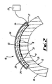
- FIG 2 there is shown a variation of the first embodiment, which is suitable for use where the surface 18 is curved.
- the features have been given the same reference numeral as in Figure 1 .
- the apparatus 10 shown in Figure 2 is curved to the same extent as the article 12.
- the apparatus 10 shown in Figure 2 is used in a similar way to the apparatus 10 shown in Figure 1 , and described above.
- FIG. 3 there is shown a second embodiment of the invention, which is similar to the embodiment shown in Figure 1 , but the heating arrangement 24 is provided over the inert member 28.
- the inert member 28 is thermally conductive to allow heat to be conducted to the pad 20.
- the apparatus 10 shown in Figure 3 is used in a similar way to the apparatus shown in Figure 1 , as would be understood by those skilled in the art.
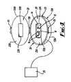
- Figure 4 shows a third embodiment, suitable for treating articles where the external surface is not planar or is complex.
- the pad 20 is held within a chemically inert casing 128.
- the casing 128 is in the form of first and second receiving members in the form of first and second casing members 128A, 128B pivotally attached together at a hinge 130.
- the first and second casing members 128A and 128B can be pivotally moved from the open position shown in Figure 4 to a closed position about the hinge 130 and locked in the closed position by a lock 131.
- the pad 20 is in the form of a first pad member 20A mounted within the first casing member 128A, and a second pad member 20A mounted within the second casing member 128A.
- the first pad member 20A defines a first recess 132A
- the second pad member 20B defines a second recess 132B.
- the pad members 20A, 20B provide respective facing portions 22A, 22B to engage the article 12.
- the first and second pad members 20A and 20B receive the article 12 in their respective recesses 132A, 132B, when the first and second casing members 128A, 128B are in their closed position.
- the recesses 132A and 132B are arranged to correspond with the shape of the region of the article 12 to be received therein.
- the recesses 132A, 132B can receive the aforesaid regions of the article in a manner that provides intimate contact between the facing portions 22A, 22B and the respective regions of the article 12.
- first and second casing members 128A and 128B apply a force to the first and second pad members 20A and 20B to provide the intimate contact between the article and the first and second pad members 20A and 20B.
- the heating arrangement 24 is provided within the first casing member 128A between the first casing member 128A and the first pad member 20A.
- the heating source 26 supplies electricity or heating fluid to the heating arrangement 24 to heat the pad 20 when the casing 128 is closed and locked.
- a pressure control means 133 is provided to increase or decrease pressure within the casing 128, when the casing 128 is closed.
- the pressure control means 133 may comprise a pump to pump air into the casing 128, thereby increasing pressure therein, or to pump air out of the casing 128, thereby decreasing the pressure therein.
- the pressure control means 133 is connected to the casing 128 by piping 135. This feature provides the advantage in this embodiment of allowing the use of volatile treatment agents, such as hydrofluorocarbons, by preventing evaporation of the volatile treatment agent at the temperatures used.
- the casing members 128A, 128B also act as the inert member, preventing leakage of the cleaning agent and transfer of heat to / from the environment.
- the pad members 20A, 20B are first impregnated with the solvent or cleaning agent, if the pad members 20A, 20B have not been supplied so impregnated.
- the article 12 is then arranged in the first and second recesses 132A, 132B.
- the first and second casing members 128A, 128B are closed, and then locked by means of the lock 131.
- the casing members 128A, 128B When the casing 128 is locked, with the casing members 128A, 128B in the closed condition, the casing members 128A, 128B press inwardly on the respective pad members 20A, 20B to effect the intimate contact of the pad 20 with the article 12, at a substantially uniform pressure.
- the heating arrangement 24 is then switched on to heat the pad 20 to a temperature in the range in the range specified in Table 1 for the relevant cleaning agent.
- the lock 131 is released, the casing 128 opened, and the article 12 is taken out.
- the contaminant can then be removed from the article 12 by washing, rinsing or wiping it off.
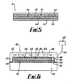
- Figure 6 is a diagrammatic sectional side view of a further embodiment of a surface treatment apparatus, generally designated 410, for cleaning the surface of an article 412, providing a substrate to be cleaned.
- the surface treatment apparatus 410 comprises an absorbent member 420 in the form of a pad of a non-woven material, such as cellulose or viscose.
- the absorbent member 420 has a facing portion thereon, in the form of a facing layer 422, which contacts the surface of the article 412 to clean it, as described below.
- the absorbent member 420 may have a facing portion, which may be a part of the absorbent member 420.
- the absorbent member 420 is provided to absorb a surface treatment medium which, in the embodiment shown, is in the form of a cleaning agent.
- the facing layer 422, or the absorbent member 420 when the absorbent member provides its own facing portion, is formed of a material which has a smoothness of substantially 5 on the American Association of Textile Colorists and Chemists. (AATCC) scale,
- a receiving member 424 is provided, which defines a recess 426, to receive the absorbent member 420.
- the receiving member 424 has an edge arrangement 428 and a main portion 430.
- the edge arrangement 428 extends from the main portion 430, and depends therefrom, to define the recess 426.
- the edge arrangement 428 comprises a wall member 432 which is attached to, and depends downwardly from, the main portion 424.
- a sealing member 434 extends from the lower edge of the wall member 432.
- the sealing member 434 is provided to seal against a base member 436, upon which the receiving member is supported.
- the sealing member 434 can engage the surface of the article 412 itself.
- the purpose of the sealing member is to prevent leakage of the surface treatment medium.
- a resistant layer 438 is provided over the absorbent member 420, and is arranged in the recess 426 between the absorbent member 420 and the receiving member 424.
- the resistant layer is in the form of a film, for example of a polyimide, such as sold under the trade mark KAPTON.
- the resistant layer 438 comprises a cover portion 439 to cover the absorbent member 420, and an edge portion 441 depending from the cover portion 439, and extending around the absorbent member 420.
- the edge portion 441 contributes to the sealing by the receiving member.
- the resistant layer 438 is chemically inert to the surface treatment medium, and thereby provides a barrier to prevent the surface treatment medium contacting the receiving member 424, which may cause damage to any heating or cooling elements in the receiving member 424.
- the heating and cooling elements are described below.
- the resistant layer 438 is also thermally stable at temperatures at which the cleaning takes place.
- Temperature control means in the form of heating and/or cooling elements 440 are provided in the receiving member 424, which are connected to a heater/cooler 442.
- the heater/cooler 442 may provide a heated or cooled fluid via a conduit arrangement 444 to the heating/cooling elements 440.
- the heating /cooling elements 440 may be electrically operated to heat or cool the receiving member, in which case, the feature designated by the numeral 442 represents an electrical controller, and the numeral 444 designates an appropriate cabling arrangement for the electrical power.
- the receiving member 424 is formed of a material that is thermally stable at the cleaning temperatures used.
- the receiving member is also chemically inert to the various surface treatment media that can be used.
- the receiving member 424 is thermally and chemically insulating, thereby allowing the surface treatment apparatus 410 to operate at temperatures that are greater or less than room temperature without any, or any significant, heat transfer with the surroundings.
- the receiving member 424 may include a pressure control means to apply a substantially uniform pressure across the absorbent member.
- the pressure control means may comprise a weight 446 within the receiving member 424. the weight 446 is shown in broken lines in Figure 6 .
- the pressure control means may comprise securing means to secure the receiving member to the base member 436, in a similar way to the lock 131 shown in Figure 4 .
- Pad Material Cellulose non-woven, backed by PETG / ACLAR polymeric film, no retaining film.
- the surface was heated to 70°C for 30 minutes, removed from system and washed with deionised water followed by air drying at room temperature.
- Superbrush finish stainless steel sheet was inoculated with 100 ⁇ l of staphylococcus Aureus suspension (10 8 cells) in milk, and allowed to dry.
- the material was subjected to a number of soil / clean cycles (1/3/6) using:
- Pad Material Cellulose non-woven, backed by PETG / fluoropolymer film, no retaining film.
- Residual Total Viable Cell Count was measured by swabbing the surface and incubating on TVA plates for 24 hours, followed by counting of viable colonies. Viable count of samples wiped without detergent gradually increased with the number of soil/clean cycles, reaching a maximum of 1.3 x 10 4 cells /cm 2 removed by swabbing. Samples cleaned using household detergent had a higher TVC count after one cycle, and lower TVC counts after the third and sixth cycle in comparison with water.
- the surface treatment method according to an embodiment of the invention had no viable microbial cells detected after all examined cleaning cycles. The results are represented below in Table B, and shown in Graph B in Figure 8 . Table B No. of Soiling Cycles Water Household Detergent Example B 1 cycle 1.15 23.6 0 3 cycles 3.65 2.45 0 6 cycles 7.7 3.8 0
- Pad Material Woven cellulosic fibre, backed by aluminium foil, no retaining film.
- Aluminium sheet coated with a layer of expandable polyurethane foam was analysed by X-ray photoelectron spectroscopy (XPS or ESCA), before and after cleaning by the cleaning process.
- XPS X-ray photoelectron spectroscopy
- XPS is a surface analysis technique that measures the topmost 10 nanometers (10x10 -9 meters) of the sample surface. All elements excluding hydrogen and helium can be measured quantitatively by XPS.
- the element compositions of the top 10 nanometer depth of the exposed surfaces are calculated from the peak intensities in Figure 9 and are listed in Table D.
- the surface composition before cleaning is typical of an organic coating, as it contains high levels of carbon with oxygen and nitrogen also present.
Landscapes
- Absorbent Articles And Supports Therefor (AREA)
- Treatment Of Fiber Materials (AREA)
- Mechanical Treatment Of Semiconductor (AREA)
Claims (14)
- Verfahren zur Behandlung einer Oberfläche eines Artikels mit einem Oberflächenbehandlungsmittel, wobei besagtes Verfahren umfasst: Bereitstellen einer Vorrichtung für Oberflächenbehandlung, die ein absorbierendes Element zum Halten des Oberflächenbehandlungsmittels umfasst, wobei besagtes absorbierendes Element einen Auflageteil zum Kontaktieren der Oberfläche aufweist, ein Montageelement eine Vertiefung zum Aufnehmen des absorbierenden Elements definiert, wobei das Montageelement eine abdichtende Einrichtung aufweist, um eine Dichtung bereitzustellen, die sich um das absorbierende Element herum erstreckt; dem absorbierenden Element zu erlauben das Oberflächenbehandlungsmittel zu halten; Kontakt zwischen dem Oberflächenbehandlungsmittel und der Oberfläche für eine ausreichende Zeit herbeizuführen, um die Behandlung der Oberfläche zu erwirken; dadurch gekennzeichnet, dass das Verfahren weiter Herbeiführen der Kupplung der Abdichteinrichtung mit entweder dem Artikel oder mit einer weiteren Komponente der Vorrichtung einschließt, um eine Dichtung gegen entweder besagten Artikel oder besagter weiterten Komponente zu bilden, um Leckage des Oberflächenbehandlungsmittels aus der Vorrichtung zu verhindern.
- Verfahren nach Anspruch 1, das Beibehalten des absorbierenden Elements in einem im Wesentlichen statischen Zustand in Bezug auf die Oberfläche, während der Behandlung der Oberfläche, umfasst.
- Verfahren nach Anspruch 1 oder 2, wobei die Abdichteinrichtung eine Kanteneinrichtung umfasst, die ein Hauptkantenelement aufweist und wobei sich ein Dichtungselement aus dem Hauptkantenelement erstreckt und, wobei das Verfahren das Herbeiführen der Kupplung des Dichtungselements mit dem Artikel oder mit einer weiteren Komponente der Vorrichtung umfasst, um die Dichtung gegen besagten Artikel oder besagte weitere Komponente zu bilden, um Leckage des Oberflächenbehandlungsmittels aus der Vorrichtung zu verhindern.
- Verfahren nach Anspruch 3, das Bereitstellen der Dichtung zwischen dem Abdichtelement und dem zu behandelnden Artikel oder zwischen dem Abdichtelement und einer weiteren Komponente der Vorrichtung umfasst.
- Verfahren nach einem beliebigen vorhergehenden Anspruch, wobei das Montageelement ein Aufnahmeelement umfasst, wobei die Vertiefung im Aufnahmeelement definiert ist und das Verfahren die Anordnung des absorbierenden Elements in der Vertiefung im Aufnahmeelement einschließt, um den zuvor genannten Kontakt zwischen dem Oberflächenbehandlungsmittel und der Oberfläche zu erwirken.
- Verfahren nach einem beliebigen vorhergehenden Anspruch, wobei der Schritt Kontaktieren des Oberflächenbehandlungsmittels mit der Oberfläche des Artikels das Herbeiführen des zuvor genannten Kontakts für eine Zeit von im Wesentlichen 5 Minuten bis im Wesentlichen 24 Stunden umfasst.
- Verfahren nach einem beliebigen vorhergehenden Anspruch, wobei der Schritt Kontaktieren des Oberflächenbehandlungsmittels mit der Oberfläche des Artikels das Herbeiführen des zuvor genannten Kontakts für eine Zeit von im Wesentlichen 15 Minuten bis im Wesentlichen 8 Stunden umfasst.
- Verfahren nach einem beliebigen vorhergehenden Anspruch, wobei der Schritt Kontaktieren des Oberflächenbehandlungsmittels mit der Oberfläche des Artikels das Herbeiführen des zuvor genannten Kontakts für eine Zeit von im Wesentlichen 20 Minuten bis im Wesentlichen 2 Stunden umfasst.
- Oberflächenbehandlungsvorrichtung zum Behandeln einer Oberfläche eines Artikels mit einem Oberflächenbehandlungsmittel, wobei die Vorrichtung umfasst: ein absorbierendes Element zum Halten des Oberflächenbehandlungsmittels, wobei das absorbierende Element einen Auflageteil zum Kontaktieren der Oberfläche aufweist; ein Montageelement eine Vertiefung zum Aufnehmen des absorbierenden Elements definiert, dadurch gekennzeichnet, dass das Montageelement einen Hauptteil und eine abdichtende Einrichtung aufweist, die sich um das absorbierende Element herum erstreckt; wobei die abdichtende Einrichtung eine Kanteneinrichtung umfasst; wobei sich die Kanteneinrichtung aus dem Hauptteil zu einem Bereich erstreckt, der mit besagtem Auflageteil auf gleicher Höhe ist oder sich über besagten Auflageteil hinaus erstreckt, um entweder den Artikel oder eine weitere Komponente der Vorrichtung in Eingriff zu bringen, um eine Dichtung gegen entweder besagten Artikel oder besagte weitere Komponente zu bilden, um Leckage des Oberflächenbehandlungsmittels aus der Vorrichtung zu verhindern.
- Oberflächenbehandlungsvorrichtung nach Anspruch 9, wobei die Kanteneinrichtung ein Hauptkantenelement und ein Abdichtelement aufweist, das sich aus dem Hauptkantenelement erstreckt, wobei das Abdichtelement konfiguriert ist, die zuvor genannte Dichtung bereitzustellen.
- Oberflächenbehandlungsvorrichtung nach Anspruch 10, die ein Basiselement einschließt, auf dem das Montageelement so montiert ist, dass die Abdichteinrichtung eine Dichtung durch in Eingriff bringen des Basiselements bilden kann, um die zuvor genannte Dichtung bereitzustellen.
- Oberflächenbehandlungsvorrichtung nach Anspruch 11, wobei sich das Basiselement unter dem Montageelement anordnen lässt.
- Oberflächenbehandlungsvorrichtung nach einem beliebigen der Ansprüche 9 bis 11, wobei sich der Hauptteil über das absorbierende Element hinaus erstreckt und die Kanteneinrichtung aus dem Hauptteil herabhängt.
- Oberflächenbehandlungsvorrichtung nach einem beliebigen der Ansprüche 9 bis 11, wobei sich das Basiselement über dem Montageelement anordnen lässt.
Applications Claiming Priority (2)
| Application Number | Priority Date | Filing Date | Title |
|---|---|---|---|
| GBGB0622396.0A GB0622396D0 (en) | 2006-11-10 | 2006-11-10 | Method and apparatus for treating a surface |
| PCT/GB2007/004218 WO2008056122A2 (en) | 2006-11-10 | 2007-11-05 | Method and apparatus for treating a surface |
Publications (2)
| Publication Number | Publication Date |
|---|---|
| EP2094404A2 EP2094404A2 (de) | 2009-09-02 |
| EP2094404B1 true EP2094404B1 (de) | 2011-08-31 |
Family
ID=37594651
Family Applications (1)
| Application Number | Title | Priority Date | Filing Date |
|---|---|---|---|
| EP07824454A Not-in-force EP2094404B1 (de) | 2006-11-10 | 2007-11-05 | Verfahren und vorrichtung zur behandlung einer oberfläche |
Country Status (4)
| Country | Link |
|---|---|
| EP (1) | EP2094404B1 (de) |
| AT (1) | ATE522283T1 (de) |
| GB (1) | GB0622396D0 (de) |
| WO (3) | WO2008056111A2 (de) |
Families Citing this family (4)
| Publication number | Priority date | Publication date | Assignee | Title |
|---|---|---|---|---|
| CN201568941U (zh) | 2008-10-15 | 2010-09-01 | 尤罗普罗操作公司 | 蒸汽器具和蒸汽熨斗 |
| US8067656B2 (en) * | 2008-11-26 | 2011-11-29 | Chevron U.S.A. Inc. | Liquid-liquid separation process via coalescers |
| US8432873B2 (en) | 2009-01-12 | 2013-04-30 | Qualcomm Incorporated | Method and apparatus for computing and reporting channel quality indication (CQI) |
| US9484123B2 (en) | 2011-09-16 | 2016-11-01 | Prc-Desoto International, Inc. | Conductive sealant compositions |
Family Cites Families (9)
| Publication number | Priority date | Publication date | Assignee | Title |
|---|---|---|---|---|
| US4336073A (en) * | 1981-08-18 | 1982-06-22 | Mack John H | Glass cleaning process and apparatus |
| US4802927A (en) * | 1987-05-20 | 1989-02-07 | Barbour Gary W | Beverage can cleaner |
| US5159735A (en) * | 1990-09-24 | 1992-11-03 | Dolores Owens | Device for cleaning toilet seats |
| US5111934A (en) * | 1991-07-22 | 1992-05-12 | Eugene Morin | Portable cleaning kit |
| DE9206173U1 (de) * | 1992-05-08 | 1992-06-25 | Hoechst Ag, 65929 Frankfurt | Reinigungsverbund für optische und magneto-optische Speicherplatten |
| US5806668A (en) * | 1996-07-01 | 1998-09-15 | Bixby; Steven H. | Containment, collection and disposal device |
| FR2777174B1 (fr) * | 1998-04-14 | 2000-06-16 | Alain Edouard Billat | Dispositif de nettoyage pour vitres, meubles et objets analogues |
| JP4046931B2 (ja) * | 2000-07-14 | 2008-02-13 | 株式会社荏原製作所 | 基板洗浄装置及び洗浄具 |
| US6584990B2 (en) * | 2001-01-19 | 2003-07-01 | Dervin International Pty. Ltd. | Steam mop |
-
2006
- 2006-11-10 GB GBGB0622396.0A patent/GB0622396D0/en not_active Ceased
-
2007
- 2007-11-05 WO PCT/GB2007/004196 patent/WO2008056111A2/en not_active Ceased
- 2007-11-05 WO PCT/GB2007/004198 patent/WO2008056112A2/en not_active Ceased
- 2007-11-05 AT AT07824454T patent/ATE522283T1/de not_active IP Right Cessation
- 2007-11-05 EP EP07824454A patent/EP2094404B1/de not_active Not-in-force
- 2007-11-05 WO PCT/GB2007/004218 patent/WO2008056122A2/en not_active Ceased
Also Published As
| Publication number | Publication date |
|---|---|
| WO2008056112A2 (en) | 2008-05-15 |
| WO2008056111A3 (en) | 2008-07-24 |
| GB0622396D0 (en) | 2006-12-20 |
| WO2008056122A3 (en) | 2008-07-24 |
| ATE522283T1 (de) | 2011-09-15 |
| WO2008056122A2 (en) | 2008-05-15 |
| EP2094404A2 (de) | 2009-09-02 |
| WO2008056111A2 (en) | 2008-05-15 |
| WO2008056112A3 (en) | 2008-07-24 |
Similar Documents
| Publication | Publication Date | Title |
|---|---|---|
| US8551253B2 (en) | Post polish disk cleaning process | |
| EP2298042B1 (de) | Verfahren zur wiederinstandsetzung von elektroden aus mehreren bestandteilen | |
| CA2040989A1 (en) | Washing/drying method and apparatus | |
| CN102899674B (zh) | 一种高真空、强辐射环境下的精密不锈钢零件的清洗方法 | |
| EP2094404A2 (de) | Verfahren und vorrichtung zur behandlung einer fläche | |
| CN100396388C (zh) | 一种前处理清洗方法 | |
| JP6946751B2 (ja) | シランカップリング剤処理方法、シランカップリング剤処理基材の製造方法および積層体の製造方法 | |
| CN102009047B (zh) | 用于将附着于被加工物的加工油减量的处理方法及其装置 | |
| KR20080095548A (ko) | 초음파 세척 및 진공 건조 방식을 이용한 광학기기용글래스 세척/건조 방법 | |
| WO2012030499A2 (en) | Workpiece wetting and cleaning | |
| TW200946254A (en) | Cleaning method and cleaning system for electronic part | |
| CN103922607A (zh) | 防污处理剂及使用该防污处理剂进行玻璃表面处理的方法 | |
| KR102404975B1 (ko) | 태양전지 패널을 재활용한 단열 패널의 제조 방법 및 이 방법에 의해 제조된 단열 패널 | |
| US10981345B2 (en) | Method and apparatus for cleaning workpiece, and method and apparatus for cleaning (pore-free) tire segment mold | |
| JP2005319377A (ja) | 洗浄方法 | |
| JP2757884B2 (ja) | 洗浄/乾燥方法及び装置 | |
| US20030186065A1 (en) | Polymeric acid protective coatings for LCD glass | |
| CN104124136A (zh) | 半导体晶片清洗方法 | |
| US20050287032A1 (en) | Anti-bacterial protection to improve performance of post CMP clean brush | |
| JP2000040684A5 (ja) | 洗浄装置および洗浄方法 | |
| CA1258998A (en) | Soluble protective film | |
| CN210259546U (zh) | 一种家用电器防护装置 | |
| KR102414240B1 (ko) | 기계식 유리막 코팅 방법 | |
| JP3548241B2 (ja) | 水すすぎ後の乾燥方法 | |
| WO1995007153A1 (en) | Method of cleaning equipment |
Legal Events
| Date | Code | Title | Description |
|---|---|---|---|
| PUAI | Public reference made under article 153(3) epc to a published international application that has entered the european phase |
Free format text: ORIGINAL CODE: 0009012 |
|
| 17P | Request for examination filed |
Effective date: 20090606 |
|
| AK | Designated contracting states |
Kind code of ref document: A2 Designated state(s): AT BE BG CH CY CZ DE DK EE ES FI FR GB GR HU IE IS IT LI LT LU LV MC MT NL PL PT RO SE SI SK TR |
|
| 17Q | First examination report despatched |
Effective date: 20090924 |
|
| DAX | Request for extension of the european patent (deleted) | ||
| GRAP | Despatch of communication of intention to grant a patent |
Free format text: ORIGINAL CODE: EPIDOSNIGR1 |
|
| GRAJ | Information related to disapproval of communication of intention to grant by the applicant or resumption of examination proceedings by the epo deleted |
Free format text: ORIGINAL CODE: EPIDOSDIGR1 |
|
| GRAP | Despatch of communication of intention to grant a patent |
Free format text: ORIGINAL CODE: EPIDOSNIGR1 |
|
| GRAS | Grant fee paid |
Free format text: ORIGINAL CODE: EPIDOSNIGR3 |
|
| GRAA | (expected) grant |
Free format text: ORIGINAL CODE: 0009210 |
|
| AK | Designated contracting states |
Kind code of ref document: B1 Designated state(s): AT BE BG CH CY CZ DE DK EE ES FI FR GB GR HU IE IS IT LI LT LU LV MC MT NL PL PT RO SE SI SK TR |
|
| REG | Reference to a national code |
Ref country code: GB Ref legal event code: FG4D Ref country code: CH Ref legal event code: EP |
|
| REG | Reference to a national code |
Ref country code: IE Ref legal event code: FG4D |
|
| REG | Reference to a national code |
Ref country code: DE Ref legal event code: R096 Ref document number: 602007016841 Country of ref document: DE Effective date: 20111027 |
|
| REG | Reference to a national code |
Ref country code: NL Ref legal event code: VDEP Effective date: 20110831 |
|
| LTIE | Lt: invalidation of european patent or patent extension |
Effective date: 20110831 |
|
| PG25 | Lapsed in a contracting state [announced via postgrant information from national office to epo] |
Ref country code: SE Free format text: LAPSE BECAUSE OF FAILURE TO SUBMIT A TRANSLATION OF THE DESCRIPTION OR TO PAY THE FEE WITHIN THE PRESCRIBED TIME-LIMIT Effective date: 20110831 Ref country code: NL Free format text: LAPSE BECAUSE OF FAILURE TO SUBMIT A TRANSLATION OF THE DESCRIPTION OR TO PAY THE FEE WITHIN THE PRESCRIBED TIME-LIMIT Effective date: 20110831 Ref country code: IS Free format text: LAPSE BECAUSE OF FAILURE TO SUBMIT A TRANSLATION OF THE DESCRIPTION OR TO PAY THE FEE WITHIN THE PRESCRIBED TIME-LIMIT Effective date: 20111231 Ref country code: FI Free format text: LAPSE BECAUSE OF FAILURE TO SUBMIT A TRANSLATION OF THE DESCRIPTION OR TO PAY THE FEE WITHIN THE PRESCRIBED TIME-LIMIT Effective date: 20110831 Ref country code: LT Free format text: LAPSE BECAUSE OF FAILURE TO SUBMIT A TRANSLATION OF THE DESCRIPTION OR TO PAY THE FEE WITHIN THE PRESCRIBED TIME-LIMIT Effective date: 20110831 |
|
| REG | Reference to a national code |
Ref country code: AT Ref legal event code: MK05 Ref document number: 522283 Country of ref document: AT Kind code of ref document: T Effective date: 20110831 |
|
| PG25 | Lapsed in a contracting state [announced via postgrant information from national office to epo] |
Ref country code: CY Free format text: LAPSE BECAUSE OF FAILURE TO SUBMIT A TRANSLATION OF THE DESCRIPTION OR TO PAY THE FEE WITHIN THE PRESCRIBED TIME-LIMIT Effective date: 20110831 Ref country code: SI Free format text: LAPSE BECAUSE OF FAILURE TO SUBMIT A TRANSLATION OF THE DESCRIPTION OR TO PAY THE FEE WITHIN THE PRESCRIBED TIME-LIMIT Effective date: 20110831 Ref country code: GR Free format text: LAPSE BECAUSE OF FAILURE TO SUBMIT A TRANSLATION OF THE DESCRIPTION OR TO PAY THE FEE WITHIN THE PRESCRIBED TIME-LIMIT Effective date: 20111201 Ref country code: AT Free format text: LAPSE BECAUSE OF FAILURE TO SUBMIT A TRANSLATION OF THE DESCRIPTION OR TO PAY THE FEE WITHIN THE PRESCRIBED TIME-LIMIT Effective date: 20110831 Ref country code: LV Free format text: LAPSE BECAUSE OF FAILURE TO SUBMIT A TRANSLATION OF THE DESCRIPTION OR TO PAY THE FEE WITHIN THE PRESCRIBED TIME-LIMIT Effective date: 20110831 |
|
| PG25 | Lapsed in a contracting state [announced via postgrant information from national office to epo] |
Ref country code: BE Free format text: LAPSE BECAUSE OF FAILURE TO SUBMIT A TRANSLATION OF THE DESCRIPTION OR TO PAY THE FEE WITHIN THE PRESCRIBED TIME-LIMIT Effective date: 20110831 |
|
| PG25 | Lapsed in a contracting state [announced via postgrant information from national office to epo] |
Ref country code: SK Free format text: LAPSE BECAUSE OF FAILURE TO SUBMIT A TRANSLATION OF THE DESCRIPTION OR TO PAY THE FEE WITHIN THE PRESCRIBED TIME-LIMIT Effective date: 20110831 Ref country code: CZ Free format text: LAPSE BECAUSE OF FAILURE TO SUBMIT A TRANSLATION OF THE DESCRIPTION OR TO PAY THE FEE WITHIN THE PRESCRIBED TIME-LIMIT Effective date: 20110831 |
|
| PG25 | Lapsed in a contracting state [announced via postgrant information from national office to epo] |
Ref country code: IT Free format text: LAPSE BECAUSE OF FAILURE TO SUBMIT A TRANSLATION OF THE DESCRIPTION OR TO PAY THE FEE WITHIN THE PRESCRIBED TIME-LIMIT Effective date: 20110831 Ref country code: EE Free format text: LAPSE BECAUSE OF FAILURE TO SUBMIT A TRANSLATION OF THE DESCRIPTION OR TO PAY THE FEE WITHIN THE PRESCRIBED TIME-LIMIT Effective date: 20110831 Ref country code: PL Free format text: LAPSE BECAUSE OF FAILURE TO SUBMIT A TRANSLATION OF THE DESCRIPTION OR TO PAY THE FEE WITHIN THE PRESCRIBED TIME-LIMIT Effective date: 20110831 Ref country code: RO Free format text: LAPSE BECAUSE OF FAILURE TO SUBMIT A TRANSLATION OF THE DESCRIPTION OR TO PAY THE FEE WITHIN THE PRESCRIBED TIME-LIMIT Effective date: 20110831 Ref country code: PT Free format text: LAPSE BECAUSE OF FAILURE TO SUBMIT A TRANSLATION OF THE DESCRIPTION OR TO PAY THE FEE WITHIN THE PRESCRIBED TIME-LIMIT Effective date: 20120102 |
|
| PG25 | Lapsed in a contracting state [announced via postgrant information from national office to epo] |
Ref country code: DK Free format text: LAPSE BECAUSE OF FAILURE TO SUBMIT A TRANSLATION OF THE DESCRIPTION OR TO PAY THE FEE WITHIN THE PRESCRIBED TIME-LIMIT Effective date: 20110831 Ref country code: MC Free format text: LAPSE BECAUSE OF NON-PAYMENT OF DUE FEES Effective date: 20111130 |
|
| REG | Reference to a national code |
Ref country code: CH Ref legal event code: PL |
|
| PLBE | No opposition filed within time limit |
Free format text: ORIGINAL CODE: 0009261 |
|
| STAA | Information on the status of an ep patent application or granted ep patent |
Free format text: STATUS: NO OPPOSITION FILED WITHIN TIME LIMIT |
|
| PG25 | Lapsed in a contracting state [announced via postgrant information from national office to epo] |
Ref country code: LI Free format text: LAPSE BECAUSE OF NON-PAYMENT OF DUE FEES Effective date: 20111130 Ref country code: CH Free format text: LAPSE BECAUSE OF NON-PAYMENT OF DUE FEES Effective date: 20111130 |
|
| 26N | No opposition filed |
Effective date: 20120601 |
|
| REG | Reference to a national code |
Ref country code: IE Ref legal event code: MM4A |
|
| REG | Reference to a national code |
Ref country code: DE Ref legal event code: R097 Ref document number: 602007016841 Country of ref document: DE Effective date: 20120601 |
|
| PG25 | Lapsed in a contracting state [announced via postgrant information from national office to epo] |
Ref country code: IE Free format text: LAPSE BECAUSE OF NON-PAYMENT OF DUE FEES Effective date: 20111105 |
|
| PG25 | Lapsed in a contracting state [announced via postgrant information from national office to epo] |
Ref country code: MT Free format text: LAPSE BECAUSE OF FAILURE TO SUBMIT A TRANSLATION OF THE DESCRIPTION OR TO PAY THE FEE WITHIN THE PRESCRIBED TIME-LIMIT Effective date: 20110831 |
|
| PG25 | Lapsed in a contracting state [announced via postgrant information from national office to epo] |
Ref country code: ES Free format text: LAPSE BECAUSE OF FAILURE TO SUBMIT A TRANSLATION OF THE DESCRIPTION OR TO PAY THE FEE WITHIN THE PRESCRIBED TIME-LIMIT Effective date: 20111211 |
|
| PG25 | Lapsed in a contracting state [announced via postgrant information from national office to epo] |
Ref country code: LU Free format text: LAPSE BECAUSE OF NON-PAYMENT OF DUE FEES Effective date: 20111105 |
|
| PG25 | Lapsed in a contracting state [announced via postgrant information from national office to epo] |
Ref country code: BG Free format text: LAPSE BECAUSE OF FAILURE TO SUBMIT A TRANSLATION OF THE DESCRIPTION OR TO PAY THE FEE WITHIN THE PRESCRIBED TIME-LIMIT Effective date: 20111130 |
|
| PG25 | Lapsed in a contracting state [announced via postgrant information from national office to epo] |
Ref country code: TR Free format text: LAPSE BECAUSE OF FAILURE TO SUBMIT A TRANSLATION OF THE DESCRIPTION OR TO PAY THE FEE WITHIN THE PRESCRIBED TIME-LIMIT Effective date: 20110831 |
|
| PG25 | Lapsed in a contracting state [announced via postgrant information from national office to epo] |
Ref country code: HU Free format text: LAPSE BECAUSE OF FAILURE TO SUBMIT A TRANSLATION OF THE DESCRIPTION OR TO PAY THE FEE WITHIN THE PRESCRIBED TIME-LIMIT Effective date: 20110831 |
|
| PGFP | Annual fee paid to national office [announced via postgrant information from national office to epo] |
Ref country code: FR Payment date: 20131031 Year of fee payment: 7 Ref country code: DE Payment date: 20131102 Year of fee payment: 7 |
|
| REG | Reference to a national code |
Ref country code: DE Ref legal event code: R119 Ref document number: 602007016841 Country of ref document: DE |
|
| REG | Reference to a national code |
Ref country code: FR Ref legal event code: ST Effective date: 20150731 |
|
| PG25 | Lapsed in a contracting state [announced via postgrant information from national office to epo] |
Ref country code: DE Free format text: LAPSE BECAUSE OF NON-PAYMENT OF DUE FEES Effective date: 20150602 |
|
| PG25 | Lapsed in a contracting state [announced via postgrant information from national office to epo] |
Ref country code: FR Free format text: LAPSE BECAUSE OF NON-PAYMENT OF DUE FEES Effective date: 20141201 |
|
| PGFP | Annual fee paid to national office [announced via postgrant information from national office to epo] |
Ref country code: GB Payment date: 20181026 Year of fee payment: 12 |
|
| GBPC | Gb: european patent ceased through non-payment of renewal fee |
Effective date: 20191105 |
|
| PG25 | Lapsed in a contracting state [announced via postgrant information from national office to epo] |
Ref country code: GB Free format text: LAPSE BECAUSE OF NON-PAYMENT OF DUE FEES Effective date: 20191105 |