EP2094432B1 - Charge d'alimentation de fil et processus de production associé - Google Patents
Charge d'alimentation de fil et processus de production associé Download PDFInfo
- Publication number
- EP2094432B1 EP2094432B1 EP07865734A EP07865734A EP2094432B1 EP 2094432 B1 EP2094432 B1 EP 2094432B1 EP 07865734 A EP07865734 A EP 07865734A EP 07865734 A EP07865734 A EP 07865734A EP 2094432 B1 EP2094432 B1 EP 2094432B1
- Authority
- EP
- European Patent Office
- Prior art keywords
- strip
- wire
- strips
- metal
- nickel
- Prior art date
- Legal status (The legal status is an assumption and is not a legal conclusion. Google has not performed a legal analysis and makes no representation as to the accuracy of the status listed.)
- Not-in-force
Links
Images

Classifications
-
- B—PERFORMING OPERATIONS; TRANSPORTING
- B21—MECHANICAL METAL-WORKING WITHOUT ESSENTIALLY REMOVING MATERIAL; PUNCHING METAL
- B21C—MANUFACTURE OF METAL SHEETS, WIRE, RODS, TUBES, PROFILES OR LIKE SEMI-MANUFACTURED PRODUCTS OTHERWISE THAN BY ROLLING; AUXILIARY OPERATIONS USED IN CONNECTION WITH METAL-WORKING WITHOUT ESSENTIALLY REMOVING MATERIAL
- B21C37/00—Manufacture of metal sheets, rods, wire, tubes, profiles or like semi-manufactured products, not otherwise provided for; Manufacture of tubes of special shape
- B21C37/04—Manufacture of metal sheets, rods, wire, tubes, profiles or like semi-manufactured products, not otherwise provided for; Manufacture of tubes of special shape of rods or wire
- B21C37/042—Manufacture of coated wire or rods
-
- B—PERFORMING OPERATIONS; TRANSPORTING
- B21—MECHANICAL METAL-WORKING WITHOUT ESSENTIALLY REMOVING MATERIAL; PUNCHING METAL
- B21C—MANUFACTURE OF METAL SHEETS, WIRE, RODS, TUBES, PROFILES OR LIKE SEMI-MANUFACTURED PRODUCTS OTHERWISE THAN BY ROLLING; AUXILIARY OPERATIONS USED IN CONNECTION WITH METAL-WORKING WITHOUT ESSENTIALLY REMOVING MATERIAL
- B21C37/00—Manufacture of metal sheets, rods, wire, tubes, profiles or like semi-manufactured products, not otherwise provided for; Manufacture of tubes of special shape
- B21C37/04—Manufacture of metal sheets, rods, wire, tubes, profiles or like semi-manufactured products, not otherwise provided for; Manufacture of tubes of special shape of rods or wire
- B21C37/045—Manufacture of wire or rods with particular section or properties
-
- B—PERFORMING OPERATIONS; TRANSPORTING
- B23—MACHINE TOOLS; METAL-WORKING NOT OTHERWISE PROVIDED FOR
- B23K—SOLDERING OR UNSOLDERING; WELDING; CLADDING OR PLATING BY SOLDERING OR WELDING; CUTTING BY APPLYING HEAT LOCALLY, e.g. FLAME CUTTING; WORKING BY LASER BEAM
- B23K35/00—Rods, electrodes, materials, or media, for use in soldering, welding, or cutting
- B23K35/02—Rods, electrodes, materials, or media, for use in soldering, welding, or cutting characterised by mechanical features, e.g. shape
- B23K35/0255—Rods, electrodes, materials, or media, for use in soldering, welding, or cutting characterised by mechanical features, e.g. shape for use in welding
- B23K35/0261—Rods, electrodes or wires
- B23K35/0272—Rods, electrodes or wires with more than one layer of coating or sheathing material
-
- B—PERFORMING OPERATIONS; TRANSPORTING
- B23—MACHINE TOOLS; METAL-WORKING NOT OTHERWISE PROVIDED FOR
- B23K—SOLDERING OR UNSOLDERING; WELDING; CLADDING OR PLATING BY SOLDERING OR WELDING; CUTTING BY APPLYING HEAT LOCALLY, e.g. FLAME CUTTING; WORKING BY LASER BEAM
- B23K35/00—Rods, electrodes, materials, or media, for use in soldering, welding, or cutting
- B23K35/22—Rods, electrodes, materials, or media, for use in soldering, welding, or cutting characterised by the composition or nature of the material
- B23K35/24—Selection of soldering or welding materials proper
- B23K35/28—Selection of soldering or welding materials proper with the principal constituent melting at less than 950°C
- B23K35/286—Al as the principal constituent
-
- B—PERFORMING OPERATIONS; TRANSPORTING
- B23—MACHINE TOOLS; METAL-WORKING NOT OTHERWISE PROVIDED FOR
- B23K—SOLDERING OR UNSOLDERING; WELDING; CLADDING OR PLATING BY SOLDERING OR WELDING; CUTTING BY APPLYING HEAT LOCALLY, e.g. FLAME CUTTING; WORKING BY LASER BEAM
- B23K35/00—Rods, electrodes, materials, or media, for use in soldering, welding, or cutting
- B23K35/22—Rods, electrodes, materials, or media, for use in soldering, welding, or cutting characterised by the composition or nature of the material
- B23K35/24—Selection of soldering or welding materials proper
- B23K35/30—Selection of soldering or welding materials proper with the principal constituent melting at less than 1550°C
- B23K35/3033—Ni as the principal constituent
-
- B—PERFORMING OPERATIONS; TRANSPORTING
- B23—MACHINE TOOLS; METAL-WORKING NOT OTHERWISE PROVIDED FOR
- B23K—SOLDERING OR UNSOLDERING; WELDING; CLADDING OR PLATING BY SOLDERING OR WELDING; CUTTING BY APPLYING HEAT LOCALLY, e.g. FLAME CUTTING; WORKING BY LASER BEAM
- B23K35/00—Rods, electrodes, materials, or media, for use in soldering, welding, or cutting
- B23K35/22—Rods, electrodes, materials, or media, for use in soldering, welding, or cutting characterised by the composition or nature of the material
- B23K35/24—Selection of soldering or welding materials proper
- B23K35/30—Selection of soldering or welding materials proper with the principal constituent melting at less than 1550°C
- B23K35/3053—Fe as the principal constituent
-
- B—PERFORMING OPERATIONS; TRANSPORTING
- B23—MACHINE TOOLS; METAL-WORKING NOT OTHERWISE PROVIDED FOR
- B23K—SOLDERING OR UNSOLDERING; WELDING; CLADDING OR PLATING BY SOLDERING OR WELDING; CUTTING BY APPLYING HEAT LOCALLY, e.g. FLAME CUTTING; WORKING BY LASER BEAM
- B23K35/00—Rods, electrodes, materials, or media, for use in soldering, welding, or cutting
- B23K35/40—Making wire or rods for soldering or welding
- B23K35/404—Coated rods; Coated electrodes
-
- B—PERFORMING OPERATIONS; TRANSPORTING
- B23—MACHINE TOOLS; METAL-WORKING NOT OTHERWISE PROVIDED FOR
- B23K—SOLDERING OR UNSOLDERING; WELDING; CLADDING OR PLATING BY SOLDERING OR WELDING; CUTTING BY APPLYING HEAT LOCALLY, e.g. FLAME CUTTING; WORKING BY LASER BEAM
- B23K35/00—Rods, electrodes, materials, or media, for use in soldering, welding, or cutting
- B23K35/40—Making wire or rods for soldering or welding
- B23K35/406—Filled tubular wire or rods
-
- C—CHEMISTRY; METALLURGY
- C23—COATING METALLIC MATERIAL; COATING MATERIAL WITH METALLIC MATERIAL; CHEMICAL SURFACE TREATMENT; DIFFUSION TREATMENT OF METALLIC MATERIAL; COATING BY VACUUM EVAPORATION, BY SPUTTERING, BY ION IMPLANTATION OR BY CHEMICAL VAPOUR DEPOSITION, IN GENERAL; INHIBITING CORROSION OF METALLIC MATERIAL OR INCRUSTATION IN GENERAL
- C23C—COATING METALLIC MATERIAL; COATING MATERIAL WITH METALLIC MATERIAL; SURFACE TREATMENT OF METALLIC MATERIAL BY DIFFUSION INTO THE SURFACE, BY CHEMICAL CONVERSION OR SUBSTITUTION; COATING BY VACUUM EVAPORATION, BY SPUTTERING, BY ION IMPLANTATION OR BY CHEMICAL VAPOUR DEPOSITION, IN GENERAL
- C23C4/00—Coating by spraying the coating material in the molten state, e.g. by flame, plasma or electric discharge
- C23C4/12—Coating by spraying the coating material in the molten state, e.g. by flame, plasma or electric discharge characterised by the method of spraying
- C23C4/131—Wire arc spraying
-
- Y—GENERAL TAGGING OF NEW TECHNOLOGICAL DEVELOPMENTS; GENERAL TAGGING OF CROSS-SECTIONAL TECHNOLOGIES SPANNING OVER SEVERAL SECTIONS OF THE IPC; TECHNICAL SUBJECTS COVERED BY FORMER USPC CROSS-REFERENCE ART COLLECTIONS [XRACs] AND DIGESTS
- Y10—TECHNICAL SUBJECTS COVERED BY FORMER USPC
- Y10T—TECHNICAL SUBJECTS COVERED BY FORMER US CLASSIFICATION
- Y10T428/00—Stock material or miscellaneous articles
- Y10T428/12—All metal or with adjacent metals
- Y10T428/12493—Composite; i.e., plural, adjacent, spatially distinct metal components [e.g., layers, joint, etc.]
- Y10T428/12736—Al-base component
-
- Y—GENERAL TAGGING OF NEW TECHNOLOGICAL DEVELOPMENTS; GENERAL TAGGING OF CROSS-SECTIONAL TECHNOLOGIES SPANNING OVER SEVERAL SECTIONS OF THE IPC; TECHNICAL SUBJECTS COVERED BY FORMER USPC CROSS-REFERENCE ART COLLECTIONS [XRACs] AND DIGESTS
- Y10—TECHNICAL SUBJECTS COVERED BY FORMER USPC
- Y10T—TECHNICAL SUBJECTS COVERED BY FORMER US CLASSIFICATION
- Y10T428/00—Stock material or miscellaneous articles
- Y10T428/12—All metal or with adjacent metals
- Y10T428/12493—Composite; i.e., plural, adjacent, spatially distinct metal components [e.g., layers, joint, etc.]
- Y10T428/12771—Transition metal-base component
- Y10T428/12861—Group VIII or IB metal-base component
- Y10T428/12944—Ni-base component
-
- Y—GENERAL TAGGING OF NEW TECHNOLOGICAL DEVELOPMENTS; GENERAL TAGGING OF CROSS-SECTIONAL TECHNOLOGIES SPANNING OVER SEVERAL SECTIONS OF THE IPC; TECHNICAL SUBJECTS COVERED BY FORMER USPC CROSS-REFERENCE ART COLLECTIONS [XRACs] AND DIGESTS
- Y10—TECHNICAL SUBJECTS COVERED BY FORMER USPC
- Y10T—TECHNICAL SUBJECTS COVERED BY FORMER US CLASSIFICATION
- Y10T428/00—Stock material or miscellaneous articles
- Y10T428/12—All metal or with adjacent metals
- Y10T428/12493—Composite; i.e., plural, adjacent, spatially distinct metal components [e.g., layers, joint, etc.]
- Y10T428/12771—Transition metal-base component
- Y10T428/12861—Group VIII or IB metal-base component
- Y10T428/12951—Fe-base component
Definitions
- This invention relates in general to wire feedstock for thermal spraying, welding and the like, and more particularly to wire feedstock having precisely controlled constituents and a process for manufacturing the same.
- aluminides which are intermetallic alloys of aluminum and other metals, can withstand high temperatures in corrosive environments, and as a consequence they find use as overlays and protective coatings on other metals, such as steel, that are readily attacked in such corrosive environments. Most often they are applied to a steel substrate by thermal spraying, particularly spraying in which the heat source is an arc struck between two electrodes. Indeed, the feedstock, which takes the form of two wires, can form the electrodes. Because both wires are consumed to provide the metal that is sprayed onto the substrate, the wires are small in cross section, often having a diameter on the order of 2,38 mm or 3,18 mm (3/32 or 1/8 inch).
- the typical wire for the wire electrodes that produce aluminides for weld overlays and coatings has a nickel or iron case and a core composed of aluminum powder.
- the arc melts both and they unite in an exothermic reaction.
- the exothermic reaction elevates the temperature of the metals and contributes to the melting of them. Rapid solidification of the metal on the steel substrate forms the aluminide, and this assures a better bond with the substrate.
- the coating contains excessive free nickel or iron and excessive free aluminum and not enough aluminide.
- the aluminide phase of the coating is deficient.
- aluminum powder has an enormous surface area along which oxygen reacts with the aluminum to form aluminum oxide, and aluminum oxide detracts from the uniformity and integrity of the coating by imparting aluminum oxide inclusions to the coating. Indeed, it contributes to a diminished production of aluminide.
- feedstock wire is equally deficient.
- a solid wire alloy of nickel and aluminum when fed into an arc or other heat source to produce a thermal spray, results in no exothermic reaction and no aluminide is deposited on the substrate.
- Some nickel-aluminum wires have an aluminum wire core with a nickel case around it (see e.g. WO91/00373 , which is considered to represent the closest state of the art). From a practical standpoint, this wire cannot be produced in diameters less than about 3,18 mm (1/8 inch), and thus it is not suitable for twin arc spraying, which requires diameters at least that small for the two wires.
- the arc tends to attach to the more conductive aluminum, and this detracts from the production of aluminide.
- Some wires are tubular, but these wires contain oxygen, which detracts from the uniformity and quality of the aluminide coating.
- Alloys have other deficiencies that sometimes render them unsuitable for wire feedstock, whether the feedstock be for spraying or welding or for some other procedure.
- the alloy of nickel and aluminum serves as an example. This alloy can contain no more than about 10% aluminum by volume, since that is as much as the nickel will accept. But some procedures, such as the deposit of aluminides by thermal spraying, demand feedstock containing a greater amount of aluminum. The same holds true for wire feedstock containing alloys other metals such as nickel and copper, known as Monel metal, which can contain no more than about 35% copper, but more copper may be desirable for some procedures.
- a wire 2 for use as a consumable electrode in a thermal spraying apparatus or for use as simply a feedstock for an arc, combustion or plasma spraying or welding apparatus, includes a nickel component 4 and an aluminum component 6, with the components 4 and 6 being in face-to-face contact throughout the cross-section of the wire 2.
- the nickel component 4 forms the exterior of the wire 2 and exceeds the aluminum component, both in weight and surface area.
- Within the wire 2 the two components 4 and 6 are in face-to-face contact along convoluted interfaces 8 that are spaced somewhat uniformly across the wire 2, typically without any bonding along the interfaces 8.
- each square of the grid 10 will possess nickel and aluminum in somewhat the same volumetric proportions.
- the nickel component 4 may be an alloy of nickel and likewise the aluminum component 6 may be an alloy of aluminum.
- a flat strip 20 of nickel and a flat strip 22 of aluminum are brought together face-to-face to provide a laminate 24 ( Fig. 2 ).
- the aluminum strip 22 will carry an aluminum oxide coating on all of its surfaces owing to the propensity of aluminum to unite with oxygen in the presence of air. That coating prevents the development of a diffusion bond between the two strips 20 and 22. Both strips 20 and 22 should be quite ductile and hence malleable.
- the width of the nickel strip 20 exceeds the width of the aluminum strip 22, which is centered over the nickel strip 20, leaving two side segments 26 of the nickel strip 20 projecting beyond the side edges of the aluminum strip 22. Even so, the volumetric proportions of nickel and aluminum are the same as that desired for the wire 2.
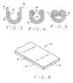
- the strips 20 and 22 are rolled into a U-shaped configuration with the narrower aluminum strip 22 being on the inside ( Fig. 3 ).
- the side segments 26 of the nickel strip 20 continue to project beyond the edges of the aluminum strip 22, but face each other and are generally parallel.
- the side segments 26 are rolled over the edges of the aluminum strip 22 to capture the aluminum strips 22 in the nickel strip 20.
- the roll forming continues and brings the side segments 26 of the nickel strip 20 against the inside face of the U-shaped aluminum strip 22 ( Fig. 4 ). This locks the two strips 20 and 22 together and produces several convolutions at the interfaces between the strips 20 and 22.
- each of the strips 20 and 22 still possess a U-shaped configuration, inasmuch as the free ends of the unbonded laminate 24 are separated.
- the laminate 24 at its free ends is then rolled or otherwise deformed inwardly so that the end edges on the side segments 26 for the nickel strip 20 come against the inside faces of the U-shaped aluminum strip 22 ( Fig. 5 ).
- the deformation also turns the aluminum strip 22 over onto itself for a short distance along the free ends of the U-shaped strip 22, that is at the former side edges of the aluminum strip 22.
- the joined together strips 20 and 22, at this juncture, in cross section possess an enclosed configuration, somewhat cylindrical, on the order of 6,35 mm to 7,62 mm (0.25 to 0.30 inches) thick.
- the joined together strips 20 and 22 are drawn through a die or rolled to a lesser diameter - typically 2,38 mm to 3,18 mm (3/32 to 1/8 inch). This consolidates the strips 20 and 22 even further and indeed causes the aluminum from the aluminum strip 22 to flow and fill voids that may otherwise exist in the wire 2 ( Fig. 1 ) that is produced.
- the wire 2 has a dense cross-section composed of a nickel component 4 and an aluminum component 6 in face-to-face contact together along a convoluted interface 8 of substantial surface area.
- the convoluted interface 8 lies not only along the inside surfaces of that portion of the nickel component 4 that forms the exterior of the wire 2, but also throughout the interior of the wire 2. This produces a generally uniform distribution of nickel and aluminum throughout the wire 2 in desired proportions.
- the wire 2 has its nickel component 4 and its aluminum component 6 in generally equal ratios throughout the cross-section as reflected in the grid 10 that is superimposed on the wire 2. Moreover, the consolidation in the final draw or roll eliminates any air gaps that previously existed in the cross-section.
- the nickel and aluminum mix well in the heat source into which the wire 2 is fed, and this fosters an exothermic reaction.
- the heat source is an arc
- that arc attaches generally uniformly across the cross-section, heating the nickel component 4 equally as well as the more conductive aluminum component 6.
- the coating deposited on a substrate to which the molten constituents are directed contains more nickel aluminide and less free nickel and less free aluminum.
- the surface area of the aluminum component 6, which equals the surface area of the aluminum strip 12 from which the component 6 derives is considerably less than the surface area of an equivalent amount of aluminum powder. Hence, less aluminum oxide is present to detract from the exothermic reaction and the subsequent quality of the coating.
- the aluminum oxide on the aluminum strip 22 produces some aluminum oxide inclusions in the deposited aluminide coating. Usually, these inclusions can be tolerated. Where they cannot, the aluminum strip 22 may be cleaned to remove aluminum oxide from it, and then the procedure for converting the laminate 24 into the wire 2 may be completed in an oxygen free atmosphere, such as an inert gas atmosphere.
- An iron strip may be substituted for the nickel strip 20 to produce a wire 2 for depositing iron-aluminide.
- a titanium strip may be substituted for the nickel strip 20 to produce a wire 2 for depositing titanium-aluminide.
- Other combinations of metals are possible as well, and they need not be formulated for the production of aluminide coatings. Indeed, some may be formulated for depositing other coatings or for other procedures such as arc welding.
- Such combinations include nickel and titanium, a nickel-chromium alloy and titanium, a nickel-chromium alloy and aluminum, and nickel and copper, to name a few. Irrespective of the combination of metals, they need not be confined to proportions represented by the limits of alloying such metals.
- an alloy of nickel and aluminum may have no more than about 10% aluminum by volume. But the nickel-aluminum wire 2 may contain a much higher percentage of aluminum. Where oxide inclusions adversely affect welds, the strips 20 and 22 used in the laminate 24 should be free of oxide coatings.
- a bonded laminate 30 ( Fig. 6 ) may be substituted for the unbonded laminate 24. It is derived from a sheet of aluminum-clad nickel having nickel lamina 32 and an aluminum lamina 34, with the two laminae 32 and 34 being diffusion bonded together along an interface 36. The volumetric proportions of the laminae 32 and 34 in the laminate 30 correspond respectively to those desired for the nickel component 4 and the aluminum component 6 in the wire 2. Indeed, the laminate 30 is rolled and drawn into the wire 2 using essentially the same process for converting the unbonded laminate 24 into the wire 2.
- the aluminum lamina 34 being bonded firmly to the nickel lamina 32 need not be initially captured in the nickel lamina 32 by rolling the ends of the nickel lamina 32 over the ends of the aluminum lamina 34. Indeed, the aluminum lamina 34, being as wide as the nickel lamina 32, leaves no side edges 26 on the nickel lamina 32 to roll over into the aluminum lamina 32.
- the wire 2 with its convoluted interface 8 may be formed in other cross-sectional configurations, such as elliptical and rectangular, including square.
Landscapes
- Engineering & Computer Science (AREA)
- Mechanical Engineering (AREA)
- Chemical & Material Sciences (AREA)
- Physics & Mathematics (AREA)
- Plasma & Fusion (AREA)
- Materials Engineering (AREA)
- Chemical Kinetics & Catalysis (AREA)
- Metallurgy (AREA)
- Organic Chemistry (AREA)
- Coating By Spraying Or Casting (AREA)
- Yarns And Mechanical Finishing Of Yarns Or Ropes (AREA)
- Sewing Machines And Sewing (AREA)
- Ropes Or Cables (AREA)
Claims (15)
- Fil (2) à utiliser comme charge d'alimentation en pulvérisation thermique et soudage, ledit fil comprenant :une première bande métallique (4) et une deuxième bande métallique (4) en contact en face à face le long d'une interface alvéolée qui s'étend tout au long de l'intérieur du fil.
- Fil selon la revendication 1 dans lequel la première bande métallique (4) forme la surface extérieure du fil (2).
- Fil selon la revendication 2 dans lequel la première bande métallique (4, 26) a une section transversale plus importante que celle de la deuxième bande métallique.
- Fil selon la revendication 2 dans lequel la deuxième bande métallique (6) est principalement en aluminium et/ou la première bande métallique (4) est fabriquée principalement à partir de l'un d'un groupe de métaux comprenant du nickel et du fer.
- Fil selon la revendication 1 dans lequel la première bande métallique (4) et la deuxième bande métallique (6) sont distribuées en proportions globalement uniformes tout au long de la section du fil (2).
- Fil selon la revendication 1 dans lequel la première bande métallique (4, 32) et la deuxième bande métallique (6, 34) sont liées entre elles par diffusion le long d'une partie de l'interface interface.
- Fil selon la revendication 1 qui est dépourvu de vides internes.
- Fil selon la revendication 1 dans lequel le volume de métal dans la deuxième bande initiale dépasse le volume de ce métal qui peut être allié avec le métal de la première bande métallique.
- Processus destiné à fabriquer un fil (2) à utiliser comme charge d'alimentation en pulvérisation thermique et soudage, ledit processus comprenant le fait de :prévoir des première (4, 26) et deuxième (6, 22) bandes métalliques en contact en face à face ;déformer les bandes en face à face selon une configuration en forme de U avec la deuxième bande (6, 22) située à l'intérieur de la première bande (4, 26) ;déformer davantage les bandes de manière à ce que les extrémités libres de la configuration en forme de U tournent intérieurement les unes vers les autres et les bandes soient ensemble le long d'une interface alvéolée ; etréduire par la suite la taille transversale des bandes.
- Processus selon la revendication 9 dans lequel la première bande (4, 26) est plus large que la deuxième bande (6, 22), et dans lequel les bandes sont réunies entre elles des segments larges de la première bande se projetant au-delà des extrémités latérales de la deuxième bande.
- Processus selon la revendication 9 dans lequel la deuxième bande (6, 22) est principalement en aluminium et/ ou la première bande (4, 26) est principalement réalisée à partir de l'un d'un groupe de métaux comprenant du nickel et du fer.
- Processus selon la revendication 9 dans lequel les bandes sont initialement séparées.
- Processus selon la revendication 9 dans lequel les bandes (4, 32 ; 6, 34) sont initialement liées (36) entre elles par diffusion.
- Processus selon la revendication 9 dans lequel la déformation finale des bandes est réalisée en étirant les bandes déjà déformées à travers une matrice.
- Processus selon la revendication 14 dans lequel la déformation initiale des bandes est réalisée par profilage.
Applications Claiming Priority (2)
| Application Number | Priority Date | Filing Date | Title |
|---|---|---|---|
| US87043706P | 2006-12-18 | 2006-12-18 | |
| PCT/US2007/087752 WO2008076967A1 (fr) | 2006-12-18 | 2007-12-17 | Charge d'alimentation de fil et processus de production associé |
Publications (2)
| Publication Number | Publication Date |
|---|---|
| EP2094432A1 EP2094432A1 (fr) | 2009-09-02 |
| EP2094432B1 true EP2094432B1 (fr) | 2011-04-13 |
Family
ID=39226645
Family Applications (1)
| Application Number | Title | Priority Date | Filing Date |
|---|---|---|---|
| EP07865734A Not-in-force EP2094432B1 (fr) | 2006-12-18 | 2007-12-17 | Charge d'alimentation de fil et processus de production associé |
Country Status (5)
| Country | Link |
|---|---|
| US (1) | US20100047616A1 (fr) |
| EP (1) | EP2094432B1 (fr) |
| AT (1) | ATE505292T1 (fr) |
| DE (1) | DE602007013936D1 (fr) |
| WO (1) | WO2008076967A1 (fr) |
Families Citing this family (6)
| Publication number | Priority date | Publication date | Assignee | Title |
|---|---|---|---|---|
| DE102016002950A1 (de) | 2016-03-11 | 2017-09-14 | Rheinisch-Westfälische Technische Hochschule (Rwth) Aachen | System zu extrakorporalen Elimination von Kohlenmonoxid |
| US12091720B2 (en) * | 2018-11-15 | 2024-09-17 | Theodor Stuth | Method for producing a raw wire from a first metal strip and at least one further metal strip by roll profiling |
| WO2022090890A1 (fr) * | 2020-10-27 | 2022-05-05 | Del Pia Srl | Fil métallique creux à composants métalliques multiples, en particulier pour l'orfèvrerie et la bijouterie fantaisie, et son procédé de mise en œuvre |
| US12551937B2 (en) * | 2022-03-23 | 2026-02-17 | The Texas A&M University System | Additive manufacturing feedstock production system for reactive wire and related methods |
| US20240003014A1 (en) * | 2022-07-01 | 2024-01-04 | General Electric Company | Method and system for thermal spraying braze alloy materials onto a nickel-based component to facilitate high density brazed joint with low discontinuities |
| CN116083836B (zh) * | 2023-02-17 | 2024-08-13 | 昆明理工大学 | 一种电弧喷涂用丝材及其制备方法 |
Family Cites Families (4)
| Publication number | Priority date | Publication date | Assignee | Title |
|---|---|---|---|---|
| GB694934A (en) * | 1949-06-20 | 1953-07-29 | Serge Gagarin | Method for manufacturing fluxed solder wires |
| US3940964A (en) * | 1974-10-01 | 1976-03-02 | Matsushita Electric Industrial Co., Ltd. | Method for making a clad wire for an electric contact |
| JPS6363599A (ja) * | 1986-09-03 | 1988-03-19 | Daido Steel Co Ltd | 溶接用フラツクス入りワイヤ |
| GB8914996D0 (en) * | 1989-06-29 | 1989-08-23 | Sprayforming Dev Ltd | An improved process for the spray forming of metals |
-
2007
- 2007-12-17 WO PCT/US2007/087752 patent/WO2008076967A1/fr not_active Ceased
- 2007-12-17 EP EP07865734A patent/EP2094432B1/fr not_active Not-in-force
- 2007-12-17 US US12/519,477 patent/US20100047616A1/en not_active Abandoned
- 2007-12-17 AT AT07865734T patent/ATE505292T1/de not_active IP Right Cessation
- 2007-12-17 DE DE602007013936T patent/DE602007013936D1/de active Active
Also Published As
| Publication number | Publication date |
|---|---|
| US20100047616A1 (en) | 2010-02-25 |
| ATE505292T1 (de) | 2011-04-15 |
| DE602007013936D1 (de) | 2011-05-26 |
| EP2094432A1 (fr) | 2009-09-02 |
| WO2008076967A1 (fr) | 2008-06-26 |
Similar Documents
| Publication | Publication Date | Title |
|---|---|---|
| EP2094432B1 (fr) | Charge d'alimentation de fil et processus de production associé | |
| US7735718B2 (en) | Layered products for fluxless brazing of substrates | |
| EP1515075A2 (fr) | Tube composite pour fourneau de la pyrolyse d'éthylène et ses procédés de fabrication | |
| JP6515359B2 (ja) | チタン複合材および熱間圧延用チタン材 | |
| RU2591867C2 (ru) | Изделие, имеющее фланец, способ изготовления такого изделия и способ изготовления изделия, содержащего элемент, имеющий фланец | |
| JP2004519330A (ja) | 鋼鉄製の母材と耐腐食性金属被覆とを有するクラッド材の製造方法 | |
| JP3176405B2 (ja) | 内面の耐食性に優れた溶接管及びその製造方法 | |
| WO2008103122A1 (fr) | Procédé de fabrication d'un composant et utilisation dudit procédé | |
| US20180355462A1 (en) | Methods for applying aluminum coating layer to a core of copper wire | |
| JP6787428B2 (ja) | 熱間圧延用チタン材 | |
| JP6039218B2 (ja) | 熱交換器用アルミニウム合金扁平管の製造方法及び熱交換器コアの製造方法 | |
| JP3355199B2 (ja) | アーク溶射用ワイヤ | |
| JP5877739B2 (ja) | 熱交換器用アルミニウム合金扁平管及びその製造方法並びに熱交換器コア及びその製造方法 | |
| JP2003117685A (ja) | 複合ろう材及びろう付加工用複合材並びにろう付け製品 | |
| JP5485774B2 (ja) | 金属製の支持部品および防食金属被覆を具備する化学装置の構成要素の製造方法 | |
| JP2957306B2 (ja) | アーク溶射用ワイヤ | |
| JP3020649B2 (ja) | クラツド鋼の製造方法 | |
| JP2006043750A (ja) | ろう付け材及びそれを用いたろう付け製品 | |
| JP2004002931A (ja) | 抵抗溶接性に優れたアルミニウムめっき鋼板とこれを用いた加工部品 | |
| CN119733753B (zh) | 一种复合金属丝材或带材的制备方法及应用 | |
| JPS6246278B2 (fr) | ||
| WO2006110178A2 (fr) | Utilisation d'une pulverisation de plasma sous atmosphere controlee, combinee a une electrodeposition, pour fabriquer une chambre de moteur-fusee | |
| CN111315518A (zh) | 钎焊接合体、钎焊方法和钎料 | |
| AU673247B2 (en) | Tube formed from steel strip having metal layer on one side | |
| JPS63235018A (ja) | 静水圧押出用複合ビレツトの製造方法 |
Legal Events
| Date | Code | Title | Description |
|---|---|---|---|
| PUAI | Public reference made under article 153(3) epc to a published international application that has entered the european phase |
Free format text: ORIGINAL CODE: 0009012 |
|
| 17P | Request for examination filed |
Effective date: 20090622 |
|
| AK | Designated contracting states |
Kind code of ref document: A1 Designated state(s): AT BE BG CH CY CZ DE DK EE ES FI FR GB GR HU IE IS IT LI LT LU LV MC MT NL PL PT RO SE SI SK TR |
|
| DAX | Request for extension of the european patent (deleted) | ||
| GRAC | Information related to communication of intention to grant a patent modified |
Free format text: ORIGINAL CODE: EPIDOSCIGR1 |
|
| GRAP | Despatch of communication of intention to grant a patent |
Free format text: ORIGINAL CODE: EPIDOSNIGR1 |
|
| GRAS | Grant fee paid |
Free format text: ORIGINAL CODE: EPIDOSNIGR3 |
|
| GRAA | (expected) grant |
Free format text: ORIGINAL CODE: 0009210 |
|
| AK | Designated contracting states |
Kind code of ref document: B1 Designated state(s): AT BE BG CH CY CZ DE DK EE ES FI FR GB GR HU IE IS IT LI LT LU LV MC MT NL PL PT RO SE SI SK TR |
|
| REG | Reference to a national code |
Ref country code: GB Ref legal event code: FG4D |
|
| REG | Reference to a national code |
Ref country code: CH Ref legal event code: EP |
|
| REG | Reference to a national code |
Ref country code: IE Ref legal event code: FG4D |
|
| REF | Corresponds to: |
Ref document number: 602007013936 Country of ref document: DE Date of ref document: 20110526 Kind code of ref document: P |
|
| REG | Reference to a national code |
Ref country code: DE Ref legal event code: R096 Ref document number: 602007013936 Country of ref document: DE Effective date: 20110526 |
|
| REG | Reference to a national code |
Ref country code: NL Ref legal event code: VDEP Effective date: 20110413 |
|
| LTIE | Lt: invalidation of european patent or patent extension |
Effective date: 20110413 |
|
| PG25 | Lapsed in a contracting state [announced via postgrant information from national office to epo] |
Ref country code: PT Free format text: LAPSE BECAUSE OF FAILURE TO SUBMIT A TRANSLATION OF THE DESCRIPTION OR TO PAY THE FEE WITHIN THE PRESCRIBED TIME-LIMIT Effective date: 20110816 Ref country code: LT Free format text: LAPSE BECAUSE OF FAILURE TO SUBMIT A TRANSLATION OF THE DESCRIPTION OR TO PAY THE FEE WITHIN THE PRESCRIBED TIME-LIMIT Effective date: 20110413 Ref country code: SE Free format text: LAPSE BECAUSE OF FAILURE TO SUBMIT A TRANSLATION OF THE DESCRIPTION OR TO PAY THE FEE WITHIN THE PRESCRIBED TIME-LIMIT Effective date: 20110413 |
|
| PG25 | Lapsed in a contracting state [announced via postgrant information from national office to epo] |
Ref country code: GR Free format text: LAPSE BECAUSE OF FAILURE TO SUBMIT A TRANSLATION OF THE DESCRIPTION OR TO PAY THE FEE WITHIN THE PRESCRIBED TIME-LIMIT Effective date: 20110714 Ref country code: BE Free format text: LAPSE BECAUSE OF FAILURE TO SUBMIT A TRANSLATION OF THE DESCRIPTION OR TO PAY THE FEE WITHIN THE PRESCRIBED TIME-LIMIT Effective date: 20110413 Ref country code: AT Free format text: LAPSE BECAUSE OF FAILURE TO SUBMIT A TRANSLATION OF THE DESCRIPTION OR TO PAY THE FEE WITHIN THE PRESCRIBED TIME-LIMIT Effective date: 20110413 Ref country code: IS Free format text: LAPSE BECAUSE OF FAILURE TO SUBMIT A TRANSLATION OF THE DESCRIPTION OR TO PAY THE FEE WITHIN THE PRESCRIBED TIME-LIMIT Effective date: 20110813 Ref country code: ES Free format text: LAPSE BECAUSE OF FAILURE TO SUBMIT A TRANSLATION OF THE DESCRIPTION OR TO PAY THE FEE WITHIN THE PRESCRIBED TIME-LIMIT Effective date: 20110724 Ref country code: SI Free format text: LAPSE BECAUSE OF FAILURE TO SUBMIT A TRANSLATION OF THE DESCRIPTION OR TO PAY THE FEE WITHIN THE PRESCRIBED TIME-LIMIT Effective date: 20110413 Ref country code: LV Free format text: LAPSE BECAUSE OF FAILURE TO SUBMIT A TRANSLATION OF THE DESCRIPTION OR TO PAY THE FEE WITHIN THE PRESCRIBED TIME-LIMIT Effective date: 20110413 Ref country code: FI Free format text: LAPSE BECAUSE OF FAILURE TO SUBMIT A TRANSLATION OF THE DESCRIPTION OR TO PAY THE FEE WITHIN THE PRESCRIBED TIME-LIMIT Effective date: 20110413 Ref country code: CY Free format text: LAPSE BECAUSE OF FAILURE TO SUBMIT A TRANSLATION OF THE DESCRIPTION OR TO PAY THE FEE WITHIN THE PRESCRIBED TIME-LIMIT Effective date: 20110413 |
|
| PG25 | Lapsed in a contracting state [announced via postgrant information from national office to epo] |
Ref country code: NL Free format text: LAPSE BECAUSE OF FAILURE TO SUBMIT A TRANSLATION OF THE DESCRIPTION OR TO PAY THE FEE WITHIN THE PRESCRIBED TIME-LIMIT Effective date: 20110413 |
|
| PG25 | Lapsed in a contracting state [announced via postgrant information from national office to epo] |
Ref country code: CZ Free format text: LAPSE BECAUSE OF FAILURE TO SUBMIT A TRANSLATION OF THE DESCRIPTION OR TO PAY THE FEE WITHIN THE PRESCRIBED TIME-LIMIT Effective date: 20110413 Ref country code: EE Free format text: LAPSE BECAUSE OF FAILURE TO SUBMIT A TRANSLATION OF THE DESCRIPTION OR TO PAY THE FEE WITHIN THE PRESCRIBED TIME-LIMIT Effective date: 20110413 |
|
| PLBE | No opposition filed within time limit |
Free format text: ORIGINAL CODE: 0009261 |
|
| STAA | Information on the status of an ep patent application or granted ep patent |
Free format text: STATUS: NO OPPOSITION FILED WITHIN TIME LIMIT |
|
| PG25 | Lapsed in a contracting state [announced via postgrant information from national office to epo] |
Ref country code: RO Free format text: LAPSE BECAUSE OF FAILURE TO SUBMIT A TRANSLATION OF THE DESCRIPTION OR TO PAY THE FEE WITHIN THE PRESCRIBED TIME-LIMIT Effective date: 20110413 Ref country code: DK Free format text: LAPSE BECAUSE OF FAILURE TO SUBMIT A TRANSLATION OF THE DESCRIPTION OR TO PAY THE FEE WITHIN THE PRESCRIBED TIME-LIMIT Effective date: 20110413 Ref country code: SK Free format text: LAPSE BECAUSE OF FAILURE TO SUBMIT A TRANSLATION OF THE DESCRIPTION OR TO PAY THE FEE WITHIN THE PRESCRIBED TIME-LIMIT Effective date: 20110413 Ref country code: PL Free format text: LAPSE BECAUSE OF FAILURE TO SUBMIT A TRANSLATION OF THE DESCRIPTION OR TO PAY THE FEE WITHIN THE PRESCRIBED TIME-LIMIT Effective date: 20110413 |
|
| 26N | No opposition filed |
Effective date: 20120116 |
|
| REG | Reference to a national code |
Ref country code: DE Ref legal event code: R097 Ref document number: 602007013936 Country of ref document: DE Effective date: 20120116 |
|
| PG25 | Lapsed in a contracting state [announced via postgrant information from national office to epo] |
Ref country code: IT Free format text: LAPSE BECAUSE OF FAILURE TO SUBMIT A TRANSLATION OF THE DESCRIPTION OR TO PAY THE FEE WITHIN THE PRESCRIBED TIME-LIMIT Effective date: 20110413 |
|
| PG25 | Lapsed in a contracting state [announced via postgrant information from national office to epo] |
Ref country code: MC Free format text: LAPSE BECAUSE OF NON-PAYMENT OF DUE FEES Effective date: 20111231 |
|
| REG | Reference to a national code |
Ref country code: CH Ref legal event code: PL |
|
| GBPC | Gb: european patent ceased through non-payment of renewal fee |
Effective date: 20111217 |
|
| REG | Reference to a national code |
Ref country code: FR Ref legal event code: ST Effective date: 20120831 |
|
| REG | Reference to a national code |
Ref country code: IE Ref legal event code: MM4A |
|
| REG | Reference to a national code |
Ref country code: DE Ref legal event code: R119 Ref document number: 602007013936 Country of ref document: DE Effective date: 20120703 |
|
| PG25 | Lapsed in a contracting state [announced via postgrant information from national office to epo] |
Ref country code: CH Free format text: LAPSE BECAUSE OF NON-PAYMENT OF DUE FEES Effective date: 20111231 Ref country code: DE Free format text: LAPSE BECAUSE OF NON-PAYMENT OF DUE FEES Effective date: 20120703 Ref country code: GB Free format text: LAPSE BECAUSE OF NON-PAYMENT OF DUE FEES Effective date: 20111217 Ref country code: LI Free format text: LAPSE BECAUSE OF NON-PAYMENT OF DUE FEES Effective date: 20111231 Ref country code: IE Free format text: LAPSE BECAUSE OF NON-PAYMENT OF DUE FEES Effective date: 20111217 |
|
| PG25 | Lapsed in a contracting state [announced via postgrant information from national office to epo] |
Ref country code: MT Free format text: LAPSE BECAUSE OF FAILURE TO SUBMIT A TRANSLATION OF THE DESCRIPTION OR TO PAY THE FEE WITHIN THE PRESCRIBED TIME-LIMIT Effective date: 20110413 |
|
| PG25 | Lapsed in a contracting state [announced via postgrant information from national office to epo] |
Ref country code: FR Free format text: LAPSE BECAUSE OF NON-PAYMENT OF DUE FEES Effective date: 20120102 |
|
| PG25 | Lapsed in a contracting state [announced via postgrant information from national office to epo] |
Ref country code: LU Free format text: LAPSE BECAUSE OF NON-PAYMENT OF DUE FEES Effective date: 20111217 |
|
| PG25 | Lapsed in a contracting state [announced via postgrant information from national office to epo] |
Ref country code: BG Free format text: LAPSE BECAUSE OF FAILURE TO SUBMIT A TRANSLATION OF THE DESCRIPTION OR TO PAY THE FEE WITHIN THE PRESCRIBED TIME-LIMIT Effective date: 20110713 |
|
| PG25 | Lapsed in a contracting state [announced via postgrant information from national office to epo] |
Ref country code: TR Free format text: LAPSE BECAUSE OF FAILURE TO SUBMIT A TRANSLATION OF THE DESCRIPTION OR TO PAY THE FEE WITHIN THE PRESCRIBED TIME-LIMIT Effective date: 20110413 |
|
| PG25 | Lapsed in a contracting state [announced via postgrant information from national office to epo] |
Ref country code: HU Free format text: LAPSE BECAUSE OF FAILURE TO SUBMIT A TRANSLATION OF THE DESCRIPTION OR TO PAY THE FEE WITHIN THE PRESCRIBED TIME-LIMIT Effective date: 20110413 |