EP2094545B1 - Procédé et dispositif pour estimer un coefficient de friction - Google Patents
Procédé et dispositif pour estimer un coefficient de friction Download PDFInfo
- Publication number
- EP2094545B1 EP2094545B1 EP07821640A EP07821640A EP2094545B1 EP 2094545 B1 EP2094545 B1 EP 2094545B1 EP 07821640 A EP07821640 A EP 07821640A EP 07821640 A EP07821640 A EP 07821640A EP 2094545 B1 EP2094545 B1 EP 2094545B1
- Authority
- EP
- European Patent Office
- Prior art keywords
- friction
- value
- determined
- coefficient
- lateral
- Prior art date
- Legal status (The legal status is an assumption and is not a legal conclusion. Google has not performed a legal analysis and makes no representation as to the accuracy of the status listed.)
- Not-in-force
Links
Images


Classifications
-
- B—PERFORMING OPERATIONS; TRANSPORTING
- B60—VEHICLES IN GENERAL
- B60T—VEHICLE BRAKE CONTROL SYSTEMS OR PARTS THEREOF; BRAKE CONTROL SYSTEMS OR PARTS THEREOF, IN GENERAL; ARRANGEMENT OF BRAKING ELEMENTS ON VEHICLES IN GENERAL; PORTABLE DEVICES FOR PREVENTING UNWANTED MOVEMENT OF VEHICLES; VEHICLE MODIFICATIONS TO FACILITATE COOLING OF BRAKES
- B60T8/00—Arrangements for adjusting wheel-braking force to meet varying vehicular or ground-surface conditions, e.g. limiting or varying distribution of braking force
- B60T8/17—Using electrical or electronic regulation means to control braking
- B60T8/172—Determining control parameters used in the regulation, e.g. by calculations involving measured or detected parameters
-
- B—PERFORMING OPERATIONS; TRANSPORTING
- B60—VEHICLES IN GENERAL
- B60W—CONJOINT CONTROL OF VEHICLE SUB-UNITS OF DIFFERENT TYPE OR DIFFERENT FUNCTION; CONTROL SYSTEMS SPECIALLY ADAPTED FOR HYBRID VEHICLES; ROAD VEHICLE DRIVE CONTROL SYSTEMS FOR PURPOSES NOT RELATED TO THE CONTROL OF A PARTICULAR SUB-UNIT
- B60W40/00—Estimation or calculation of non-directly measurable driving parameters for road vehicle drive control systems not related to the control of a particular sub unit, e.g. by using mathematical models
- B60W40/02—Estimation or calculation of non-directly measurable driving parameters for road vehicle drive control systems not related to the control of a particular sub unit, e.g. by using mathematical models related to ambient conditions
- B60W40/06—Road conditions
- B60W40/068—Road friction coefficient
-
- B—PERFORMING OPERATIONS; TRANSPORTING
- B60—VEHICLES IN GENERAL
- B60T—VEHICLE BRAKE CONTROL SYSTEMS OR PARTS THEREOF; BRAKE CONTROL SYSTEMS OR PARTS THEREOF, IN GENERAL; ARRANGEMENT OF BRAKING ELEMENTS ON VEHICLES IN GENERAL; PORTABLE DEVICES FOR PREVENTING UNWANTED MOVEMENT OF VEHICLES; VEHICLE MODIFICATIONS TO FACILITATE COOLING OF BRAKES
- B60T2210/00—Detection or estimation of road or environment conditions; Detection or estimation of road shapes
- B60T2210/10—Detection or estimation of road conditions
- B60T2210/12—Friction
-
- B—PERFORMING OPERATIONS; TRANSPORTING
- B60—VEHICLES IN GENERAL
- B60T—VEHICLE BRAKE CONTROL SYSTEMS OR PARTS THEREOF; BRAKE CONTROL SYSTEMS OR PARTS THEREOF, IN GENERAL; ARRANGEMENT OF BRAKING ELEMENTS ON VEHICLES IN GENERAL; PORTABLE DEVICES FOR PREVENTING UNWANTED MOVEMENT OF VEHICLES; VEHICLE MODIFICATIONS TO FACILITATE COOLING OF BRAKES
- B60T2230/00—Monitoring, detecting special vehicle behaviour; Counteracting thereof
- B60T2230/02—Side slip angle, attitude angle, floating angle, drift angle
Definitions
- the invention relates to a method and a corresponding device for estimating a friction coefficient between at least one tire of a vehicle and a roadway.
- the DE 39 120 14 A1 discloses a method for determining a coefficient of friction between a roadway and a tire of a vehicle.
- values for a steering angle, a driving speed, a yawing angular velocity and a lateral acceleration of the vehicle are respectively detected or determined.
- a reference or desired yaw angular velocity is determined on the basis of a mathematical vehicle reference model.
- a difference between the actual yaw rate of the vehicle and the reference or target yaw rate is determined.
- the value of the lateral acceleration is determined as a measure of the coefficient of friction between the road surface and the tires of the vehicle at which the difference between the actual yaw rate and the reference yaw rate begins to increase sharply.
- the EP 1 627 790 A1 discloses a method for estimating a friction coefficient.
- a steering angle and a lateral acceleration are detected.
- An estimated value of the friction coefficient is determined by means of a table.
- several areas for different steering angles and transverse accelerations are provided, which are assigned a plurality of friction coefficients.
- the associated area of the table is selected and the assigned friction coefficient is used as an estimate of the friction coefficient.
- the object of the invention is to provide a method and a corresponding apparatus for estimating a friction coefficient that is reliable.
- the invention is characterized by a method and a corresponding device for estimating a friction coefficient between at least one tire of a vehicle and a roadway.
- a slip angle is detected or determined.
- a lateral friction value between at least one tire of the vehicle and the roadway is determined by means of a model in which a functional relationship between the lateral friction value and the slip angle is predetermined such that a nonlinear profile of the lateral friction value with respect to the slip angle depends on a Initial slope of the lateral coefficient of friction with respect to the slip angle and of a recursively determined friction coefficient estimate.
- the functional relationship is predetermined such that the initial slope is substantially independent of the recursively determined estimated value of the friction coefficient.
- a vehicle dynamics measurement of the vehicle is detected.
- a vehicle dynamic model variable corresponding to the dynamic driving quantity is determined. Furthermore, a deviation between the driving dynamic measured variable and the driving dynamic model size is determined.
- the recursion in determining the estimated value of the friction coefficient comprises that it is adjusted as a function of the determined deviation.
- the slip angle is defined as the angle between a wheel plane perpendicular to a wheel axis and a direction of movement of a contact area in which the tire and the road touch.
- the lateral friction value is defined as the quotient of a lateral force acting on the tire and a tire treading force on the roadway.
- the friction coefficient characterizes the friction between the tire and the road surface and is defined as the quotient of a maximum force that can be transmitted by the tire to the roadway in the direction parallel to the road surface and the standing force or as a limit value of this ratio for large slip values.
- the initial gradient is understood to be a gradient of a curve for the lateral coefficient of friction over the slip angle for small skew angles.
- the initial slope corresponds to a threshold value of the slope of the curve for zero slip angle.
- the driving-dynamic measured variable and the driving-dynamic model size relate, for example, to a lateral acceleration or a yaw rate of the vehicle or to another suitable variable which can be detected by means of sensors or determined from acquired measured values and can be determined within the model as a function of the lateral friction value.
- the invention is based on the finding that the estimation of the friction coefficient is particularly robust and reliable if a model is used for determining the lateral friction value, in which the initial slope of the lateral friction value with respect to the slip angle is substantially independent of the recursively determined estimated value of the friction coefficient Reibkennress is specified and in particular is given constant. Due to the functional relationship between the lateral coefficient of friction and the slip angle according to the model, the non-linear profile of the lateral coefficient of friction with respect to the slip angle is thus largely predetermined and is essentially only dependent on the estimated value of the coefficient of friction. Changes in the friction coefficient are so easy and reliable recognizable.
- the benefit of this functional relationship for determining the lateral coefficient of friction has the advantage that the lateral coefficient of friction can be easily determined in this way and the initial slope of the lateral coefficient of friction with respect to the slip angle is substantially independent of the recursively determined coefficient of the friction index and also substantially is constant. This allows a reliable and accurate estimation of the friction coefficient.
- a vehicle has an evaluation device 1 and sensors ( FIG. 1 ).
- the sensors are coupled to the evaluation device 1.
- the sensors are in particular designed for detecting driving dynamic measured variables.
- Such sensors are in particular a lateral acceleration sensor 2 for detecting a detected lateral acceleration a_y and / or a yaw rate sensor 3 for detecting a detected yaw rate w_z and / or a steering wheel angle sensor 4 for detecting a steering wheel angle.
- a wheel speed sensor is preferably on each wheel of the vehicle 5 arranged to detect each one wheel speed rd.
- the sensors are in each case coupled to the evaluation device 1 and supply the respectively acquired measured values to them.
- other sensors may also be provided, for example a longitudinal acceleration sensor.
- a signal processing unit SIG is provided for processing the measured values supplied by the sensors of the evaluation device 1 ( FIG. 2 ). Furthermore, an estimation unit EST is provided, which is coupled on the input side to an output of the signal conditioning unit SIG.
- the signal processing unit SIG in particular receives the detected wheel speeds rd, the detected lateral acceleration a_y and the detected yaw rate w_z.
- the signal conditioning unit SIG can also be supplied with measured values of further measured variables.
- the processing of the respective measured values comprises, for example, a filtering and in particular a low-pass filtering and / or a correction or conversion of the acquired measured values.
- the signal processing unit SIG can be configured to determine measured variables derived from the supplied measured values, for example taking vehicle-dynamic vehicle models into account or by simply calculating two or more of the measured values of different measured variables into a measured value of a measured variable derived therefrom.
- a derived measured variable is, for example, a vehicle speed v, which can be determined as a function of the detected wheel speeds rd, or a contact force F_z which is exerted perpendicular to the roadway via a wheel of the vehicle.
- a slip angle ⁇ can be determined as a function of the detected yaw rate w_z.
- the said derived measured variables may also be determined or recorded differently.
- the estimation unit EST is designed, depending on the detected or determined measured values supplied to it Estimate a friction coefficient ⁇ _R between at least one tire of the vehicle and a road to determine.
- a lateral coefficient of friction ⁇ _T is determined as a function of the detected or determined slip angle ⁇ by means of a model.
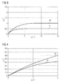
- a nonlinear functional relationship exists in the model, which is present in a first curve k1 and a second curve k2 for different estimated values of the friction coefficient ⁇ _R in FIGS. 3 and 4 is shown by way of example.
- the estimated value of the friction coefficient ⁇ _R is 0.5 for the first curve k1 and 1 for the second curve.
- An initial slope of the lateral friction coefficient ⁇ _T with respect to the slip angle ⁇ is substantially independent of the estimated value of the friction coefficient ⁇ _R and is preferably constant.
- a first parameter C1 is specified as a product of the estimated value of the friction coefficient ⁇ _R and a first constant C1_0
- a second parameter is specified as a quotient of a second constant C2_0 and the estimated value of the friction coefficient ⁇ _R.
- the first constant C1_0 has a value of about 1
- the second constant C2_0 has a value of about 25.
- the first and the second constant C1_0, C2_0 can also be specified differently.
- a third parameter C3 preferably has a small value, for example about 0.2.
- the term -C3 ⁇ S is negligible.
- the value of the third parameter C3 is zero. The determination of the lateral coefficient of friction ⁇ _T is thus particularly simple.
- the simplified representation 1_C2 ⁇ S results for the exponential function with the argument -C2 ⁇ S.
- the initial slope of the lateral friction coefficient ⁇ _T with respect to the slip angle ⁇ is thus substantially independent of the estimated value of the friction coefficient ⁇ _R and is also substantially constant.
- Such a relationship between the lateral coefficient of friction ⁇ _T and the skew angle ⁇ enables a particularly reliable and robust estimation of the friction coefficient ⁇ _R.
- the nonlinear functional relationship between the lateral coefficient of friction ⁇ _T and the slip angle ⁇ can also be specified differently.
- FIG. 5 shows a flowchart of a program for estimating the friction coefficient ⁇ _R.
- the program starts in a step S1.
- the estimated value of the friction coefficient ⁇ _R for a time t-1 is assigned a predetermined value, for example 1.
- a step S3 the product of the estimated value of the friction coefficient ⁇ _R at time t-1 and the first constant C1_0 is assigned to the first parameter C1. Furthermore, the second parameter C2 is assigned the quotient of the second constant C2_0 and the estimated value of the friction coefficient ⁇ _R at the time t-1.
- the slip angle ⁇ , the contact force F_z, the vehicle speed v and the detected lateral acceleration a_y are detected or determined.
- the predefined lower transverse acceleration limit value a_th is, for example, about 0.5 m / s 2 , but may also be greater than or less than 0.5 m / s 2 . Further, in step S5 preferably checks whether the vehicle speed v is less than a predetermined lower speed limit v_th.
- the predetermined lower speed limit v_th is for example about 5 m / s, but may also be greater than or less than 5 m / s. If the conditions in step S5 are fulfilled, the program is continued in step S3.
- a determined lateral acceleration a_y_c is determined as a vehicle dynamic model variable as a function of the determined lateral friction coefficient ⁇ _T and is preferably smoothed by low-pass filtering.
- a transverse force F_y is determined as the product of the determined lateral coefficient of friction ⁇ _T and the contact force F_z. The determined lateral acceleration a_y_c can then be determined as a function of the determined transverse force F_y.
- a step S8 it is preferably checked whether the detected lateral acceleration a_y is within a predetermined tolerance band about the determined lateral acceleration a_y_c.
- a lower limit of the predetermined tolerance band is specified as a difference between an amount of the determined lateral acceleration a_y_c and a lower acceleration tolerance limit a_min.
- an upper limit of the predetermined tolerance band is predetermined by a sum of the magnitude of the determined lateral acceleration a_y_c and an upper acceleration tolerance limit value a max. If the amount of the detected lateral acceleration a_y lies within the predetermined tolerance band, then the program is continued in step S3. Otherwise, the estimated value of the friction coefficient ⁇ _R is adjusted in a step S9.
- the adjustment of the estimated value of the friction coefficient ⁇ _R is such that the estimated value of the friction coefficient ⁇ _R at a time t is a difference of the estimated value of the friction coefficient ⁇ _R at the time t-1 and a product of a factor K and a Difference of the amount of the determined lateral acceleration a_y_c and the amount of the detected lateral acceleration a_y is assigned.
- the estimated value of the friction coefficient ⁇ _R at time t is also assigned to the estimated value of the friction coefficient ⁇ _R at time t-1 for a subsequent adaptation step according to steps S3 to S9.
- the program is continued in step S3. In this way, the estimated value of the friction coefficient ⁇ _R is determined recursively.
- the program is preferably continued only after expiration of a waiting period T_W.
- the waiting period T_W corresponds, for example, to a sampling interval in which the measured values are detected or determined, or to a predetermined time interval for adjusting and thus updating the estimated value of the friction index ⁇ _R.
- the factor K is for example given as about 1.5 s / m ⁇ T_W. However, the factor K can also be specified differently.
- the program can also be carried out accordingly if, instead of the detected and the determined lateral acceleration a_y, a_y_c, the detected and a determined yaw rate w_z, w_z_c are used for estimating the friction coefficient ⁇ _R.
- a step S11 is provided in which the slip angle ⁇ , the contact force F_z, the vehicle speed v and the detected yaw rate w_z are detected or determined.
- a step S12 replacing step S5
- it is checked whether an amount of the detected yaw rate w_z is smaller than a predetermined lower yaw rate limit w_th and whether the vehicle speed is less than the predetermined lower speed limit v_th.
- a step S13 is provided in which the determined yaw rate w_z_c is determined as a vehicle-dynamic model variable as a function of the determined lateral coefficient of friction ⁇ _T and is preferably smoothed by low-pass filtering.
- a step S14 is provided in which it is checked whether an amount of the detected yaw rate w_z lies within a predetermined tolerance band around the determined yaw rate w_z_c.
- a lower one Limit of the predetermined tolerance band is predetermined by a difference of an amount of the determined yaw rate w_z_c and a lower yaw rate tolerance limit w_min.
- An upper limit of the predetermined tolerance band is predetermined by a sum of the magnitude of the determined yaw rate w_z_c and an upper yaw rate tolerance limit w_max.
- adjusting the estimated value of the friction coefficient ⁇ _R in a step S15 is fed in step S15 a difference of the estimated value of the friction coefficient ⁇ _R at time t-1 and a product of the factor K and a difference of the amount of the determined yaw rate w_z_c and the amount of the detected yaw rate w_z.
- the program can also be carried out if, instead of the detected and the determined lateral acceleration a_y, a_y_c or the detected and the determined yaw rate w_z, w_z_c are used for estimating the friction coefficient ⁇ _R other driving dynamics variables that can be detected as a measurand and determined as a model size ,
- Such other driving dynamics variables are, for example, a yaw acceleration or a yaw moment.
Landscapes
- Engineering & Computer Science (AREA)
- Transportation (AREA)
- Mechanical Engineering (AREA)
- Physics & Mathematics (AREA)
- Automation & Control Theory (AREA)
- Mathematical Physics (AREA)
- Control Of Driving Devices And Active Controlling Of Vehicle (AREA)
- Pressure Welding/Diffusion-Bonding (AREA)
Claims (3)
- Procédé pour estimer un coefficient de frottement (µ_R) entre au moins un pneumatique d'un véhicule automobile et une chaussée, au cours duquel- on mesure ou on détermine un angle de dérive du pneumatique (α),- on détermine une valeur de frottement latéral (µ_T) entre ledit au moins un pneumatique du véhicule automobile et la chaussée au moyen d'un modèle dans lequel une relation fonctionnelle entre la valeur de frottement latéral (µ_T) et l'angle de dérive du pneumatique (α) est prédéterminée de telle manière qu'une évolution non linéaire de la valeur de frottement latéral (µ_T) par rapport à l'angle de dérive du pneumatique (α) soit dépendante d'un accroissement initial de la valeur de frottement latéral (µ_T) par rapport à l'angle de dérive du pneumatique (α) et d'une valeur estimée, déterminée de façon récursive, du coefficient de frottement (µ_R) et d'une manière telle que l'accroissement initial soit indépendant de la valeur estimée du coefficient de frottement (µ_R) déterminée de façon récursive, ,- on détermine une grandeur de mesure relative à la dynamique de mouvement du véhicule automobile,- en fonction de la valeur de frottement latéral (µ_T), on détermine une grandeur de modèle, relative à la dynamique de mouvement, qui correspond à la grandeur de mesure, relative à la dynamique de mouvement, et on détermine un écart entre la grandeur de mesure, relative à la dynamique de mouvement, et la grandeur de modèle, relative à la dynamique de mouvement.,- la récursivité lors de la détermination de la valeur estimée du coefficient de frottement (µ_R) impliquant d'adapter celle-ci en fonction de l'écart ainsi déterminé.
- Procédé selon la revendication 1 dans lequel la relation fonctionnelle dans le modèle est donnée par


Avec une première et une deuxième constante (C1_0, C2_0). - Dispositif pour estimer un coefficient de frottement (µ_R) entre au moins un pneumatique d'un véhicule automobile et une chaussée, qui est conçu pour- mesurer ou déterminer un angle de dérive de pneumatique (α),- déterminer une valeur de frottement latéral (µ_T) entre ledit au moins un pneumatique du véhicule automobile et la chaussée au moyen d'un modèle dans lequel une relation fonctionnelle entre la valeur de frottement latéral (µ_T) et l'angle de dérive du pneumatique (α) est prédéterminée de telle manière qu'une évolution non linéaire de la valeur de frottement latéral (µ_T) par rapport à l'angle de dérive du pneumatique (α) soit dépendante d'un accroissement initial de la valeur de frottement latéral (µ_T) par rapport à l'angle de dérive du pneumatique (α) et d'autre part d'une valeur estimée, déterminée de façon récursive, du coefficient de frottement (µ_R) et de telle manière que l'accroissement initial soit indépendant de la valeur estimée du coefficient de frottement (µ_R), déterminée de façon récursive,- déterminer une grandeur de mesure relative à la dynamique de mouvement du véhicule automobile,- déterminer une grandeur de modèle, dynamique relative à la dynamique du mouvement, qui correspond à la grandeur de mesure, relative à la dynamique de mouvement, en fonction de la valeur de frottement latéral (µ_T), et déterminer un écart entre la grandeur de mesure, relative à la dynamique de mouvement, et la grandeur de modèle, relative à la dynamique de mouvement,- déterminer de façon récursive la valeur estimée du coefficient de frottement (µ_R), la récursivité impliquant d'adapter la valeur estimée en fonction de l'écart ainsi déterminé.
Applications Claiming Priority (2)
| Application Number | Priority Date | Filing Date | Title |
|---|---|---|---|
| DE102006054805A DE102006054805B4 (de) | 2006-11-21 | 2006-11-21 | Verfahren und Vorrichtung zum Schätzen einer Reibkennzahl |
| PCT/EP2007/061276 WO2008061852A1 (fr) | 2006-11-21 | 2007-10-22 | Procédé et dispositif pour estimer un coefficient de friction |
Publications (2)
| Publication Number | Publication Date |
|---|---|
| EP2094545A1 EP2094545A1 (fr) | 2009-09-02 |
| EP2094545B1 true EP2094545B1 (fr) | 2010-03-31 |
Family
ID=38917803
Family Applications (1)
| Application Number | Title | Priority Date | Filing Date |
|---|---|---|---|
| EP07821640A Not-in-force EP2094545B1 (fr) | 2006-11-21 | 2007-10-22 | Procédé et dispositif pour estimer un coefficient de friction |
Country Status (8)
| Country | Link |
|---|---|
| US (1) | US8370019B2 (fr) |
| EP (1) | EP2094545B1 (fr) |
| JP (1) | JP5039143B2 (fr) |
| KR (1) | KR101391195B1 (fr) |
| CN (1) | CN101636299B (fr) |
| AT (1) | ATE462624T1 (fr) |
| DE (2) | DE102006054805B4 (fr) |
| WO (1) | WO2008061852A1 (fr) |
Families Citing this family (10)
| Publication number | Priority date | Publication date | Assignee | Title |
|---|---|---|---|---|
| US9221439B2 (en) * | 2009-02-16 | 2015-12-29 | Honda Motor Co., Ltd. | Road surface frictional coefficient estimating apparatus |
| JP5396116B2 (ja) * | 2009-03-25 | 2014-01-22 | 本田技研工業株式会社 | 摩擦状態推定装置 |
| DE102015005018B4 (de) | 2015-04-20 | 2021-06-10 | Audi Ag | Verfahren zur Bestimmung des lateralen Reibwerts zwischen mindestens einem Reifen eines Fahrzeugs und einer Fahrbahn |
| KR101876063B1 (ko) * | 2016-10-04 | 2018-07-06 | 현대자동차주식회사 | 차량 데이터 기반의 노면 판단 방법 |
| DE102016221932A1 (de) * | 2016-11-09 | 2018-05-09 | Robert Bosch Gmbh | Verfahren und Vorrichtung zum Betreiben eines Fahrerassistenzsystems, Fahrerassistenzsystem |
| US10093321B1 (en) * | 2017-03-23 | 2018-10-09 | Mitsubishi Electric Research Laboratories, Inc. | System and method for calibrating parameters of tires |
| US11062538B2 (en) | 2018-06-05 | 2021-07-13 | Robert Bosch Automotive Steering Llc | Steering rack corrosion detection using steering data |
| KR102689881B1 (ko) * | 2019-11-12 | 2024-08-01 | 현대자동차주식회사 | 친환경 차량 및 그 모터 토크 제어 방법 |
| CN113978470B (zh) * | 2021-12-13 | 2024-01-12 | 郑州轻工业大学 | 轮胎与路面摩擦力在线快速估计方法 |
| GB2618613A (en) * | 2022-05-13 | 2023-11-15 | Airbus Operations Ltd | A method of determining a tire performance characteristic of a tire |
Family Cites Families (21)
| Publication number | Priority date | Publication date | Assignee | Title |
|---|---|---|---|---|
| DE3912014C2 (de) * | 1989-04-12 | 1998-07-09 | Bayerische Motoren Werke Ag | Verfahren zur Ermittlung des Reibwertes zwischen der Fahrbahn und den Reifen eines Fahrzeuges |
| JP3119010B2 (ja) * | 1993-03-03 | 2000-12-18 | 株式会社デンソー | 路面摩擦係数検出装置 |
| DE19549715B4 (de) * | 1994-06-27 | 2004-09-16 | Fuji Jukogyo K.K. | Verfahren zur Bestimmung des Fahrbahnreibwertes für ein Steuersystem in einem Kraftfahrzeug |
| JP3268124B2 (ja) * | 1994-06-27 | 2002-03-25 | 富士重工業株式会社 | 車両のトルク配分制御装置 |
| US5774821A (en) * | 1994-11-25 | 1998-06-30 | Itt Automotive Europe Gmbh | System for driving stability control |
| DE19515050A1 (de) * | 1994-11-25 | 1996-05-30 | Teves Gmbh Alfred | Verfahren zur Fahrstabilitätsregelschaltung mit Steuerung über Druckgradienten |
| US5576959A (en) * | 1995-03-03 | 1996-11-19 | Ford Motor Company | Method for controlling yaw of a wheeled vehicle based on under-steer and over-steer containment routines |
| US5869753A (en) * | 1995-08-25 | 1999-02-09 | Honda Giken Kogyo Kabushiki Kaisha | System for estimating the road surface friction |
| JP3060923B2 (ja) | 1995-11-24 | 2000-07-10 | トヨタ自動車株式会社 | 車両状態推定装置 |
| US5899952A (en) * | 1995-12-27 | 1999-05-04 | Toyota Jidosha Kabushiki Kaisha | Device for estimating slip angle of vehicle body through interrelation thereof with yaw rate |
| JP2000025594A (ja) * | 1998-05-07 | 2000-01-25 | Unisia Jecs Corp | 車両のヨ―運動制御装置 |
| JP2002012160A (ja) | 2000-06-29 | 2002-01-15 | Fuji Heavy Ind Ltd | 車両の路面摩擦係数推定装置 |
| JP3539722B2 (ja) * | 2000-11-16 | 2004-07-07 | 富士重工業株式会社 | 車両の路面摩擦係数推定装置 |
| JP3702779B2 (ja) * | 2000-12-05 | 2005-10-05 | トヨタ自動車株式会社 | 車両の挙動制御装置 |
| JP3798668B2 (ja) * | 2001-10-11 | 2006-07-19 | 本田技研工業株式会社 | 路面摩擦係数の算出装置 |
| JP3860518B2 (ja) * | 2002-08-12 | 2006-12-20 | 株式会社豊田中央研究所 | 路面摩擦状態推定装置 |
| JP3997864B2 (ja) * | 2002-08-14 | 2007-10-24 | トヨタ自動車株式会社 | 車輪状態取得装置および車両状態取得装置 |
| JP4127062B2 (ja) * | 2003-01-22 | 2008-07-30 | トヨタ自動車株式会社 | 横加速度センサのドリフト量推定装置、横加速度センサの出力補正装置及び路面摩擦状態推定装置 |
| JP4703953B2 (ja) * | 2003-08-26 | 2011-06-15 | 富士重工業株式会社 | 車両の路面摩擦係数推定装置 |
| JP4397760B2 (ja) * | 2004-08-20 | 2010-01-13 | 本田技研工業株式会社 | 路面摩擦係数の推定方法 |
| DE602005004847T2 (de) * | 2004-08-19 | 2009-02-19 | Honda Motor Co., Ltd. | Verfahren zur Bestimmung des Reibwerts einer Strassenoberfläche und des Rutschwinkels eines Kraftfahrzeugs |
-
2006
- 2006-11-21 DE DE102006054805A patent/DE102006054805B4/de not_active Expired - Fee Related
-
2007
- 2007-10-22 WO PCT/EP2007/061276 patent/WO2008061852A1/fr not_active Ceased
- 2007-10-22 AT AT07821640T patent/ATE462624T1/de active
- 2007-10-22 JP JP2009537582A patent/JP5039143B2/ja not_active Expired - Fee Related
- 2007-10-22 DE DE502007003359T patent/DE502007003359D1/de active Active
- 2007-10-22 KR KR1020097012995A patent/KR101391195B1/ko not_active Expired - Fee Related
- 2007-10-22 CN CN2007800431212A patent/CN101636299B/zh not_active Expired - Fee Related
- 2007-10-22 EP EP07821640A patent/EP2094545B1/fr not_active Not-in-force
- 2007-10-22 US US12/515,573 patent/US8370019B2/en not_active Expired - Fee Related
Also Published As
| Publication number | Publication date |
|---|---|
| ATE462624T1 (de) | 2010-04-15 |
| US20100145566A1 (en) | 2010-06-10 |
| JP5039143B2 (ja) | 2012-10-03 |
| DE102006054805B4 (de) | 2009-11-26 |
| KR20090085691A (ko) | 2009-08-07 |
| DE102006054805A1 (de) | 2008-05-29 |
| WO2008061852A1 (fr) | 2008-05-29 |
| US8370019B2 (en) | 2013-02-05 |
| EP2094545A1 (fr) | 2009-09-02 |
| CN101636299B (zh) | 2013-02-06 |
| CN101636299A (zh) | 2010-01-27 |
| DE502007003359D1 (de) | 2010-05-12 |
| KR101391195B1 (ko) | 2014-05-02 |
| JP2010510130A (ja) | 2010-04-02 |
Similar Documents
| Publication | Publication Date | Title |
|---|---|---|
| WO2008061852A1 (fr) | Procédé et dispositif pour estimer un coefficient de friction | |
| DE69614975T2 (de) | Vorrichtung zur Bestimmung einer geschätzten Bewegungszustandsgrösse eines Fahrzeuges | |
| WO2010034580A1 (fr) | Procédé et dispositif pour déterminer le centre de gravité d'un véhicule automobile | |
| WO2008077670A1 (fr) | Procédé et dispositif de détermination d'un indice de friction | |
| DE102006018974A1 (de) | Verfahren zur Kalibrierung einer Gierratenmessung | |
| DE69723186T2 (de) | Verfahren und Einrichtung zur Erkennung von Reifendruckverlust | |
| DE10130877B4 (de) | Vorrichtung zur Abschätzung der Fahrbahnreibung | |
| EP1152933B1 (fr) | Procede et dispositif pour la surveillance de plusieurs capteurs detectant un processus, en particulier pour un systeme de programme electronique de stabilite pour vehicules | |
| WO2010034578A1 (fr) | Procédé et dispositif pour déterminer la masse totale d'un véhicule automobile | |
| DE102018004057A1 (de) | Verfahren und System zum Bestimmen des Versatzes eines Lenkradwinkelsensors | |
| EP1949112B1 (fr) | Procédé pour déterminer des dérives à long terme du décalage de capteurs d'acceleration dans des vehicules automobiles | |
| DE10314998B4 (de) | Verfahren und Vorrichtung zur Ermittlung des Offsetwerts eines Längsbeschleunigungssensors | |
| EP2114706B1 (fr) | Procédé et dispositif pour déterminer un décalage de signal d'un capteur de taux de roulis | |
| EP4326599B1 (fr) | Procédé mis en oeuvre par ordinateur pour détecter un état d'intervention sur un volant, produit-programme d'ordinateur, système d'aide à la conduite et véhicule à moteur | |
| DE102019113490A1 (de) | Verfahren zur Plausibilisierung einer Querbeschleunigung und einer Anzahl weiterer Eingangsgrößen eines Getriebeschaltprogramms eines automatisierten Schaltgetriebes eines Kraftfahrzeugs | |
| DE102018125892A1 (de) | Verfahren zur Plausibilisierung einer Querbeschleunigung eines nicht spurgebundenen, zweispurigen Kraftfahrzeugs | |
| DE102004041072B4 (de) | Verfahren zur Fahrzeugsteuerung | |
| EP1795881B1 (fr) | Procédé et dispositif à l'évaluation de l'état de fonctionnement d'un pneu de véhicule | |
| EP2057054A1 (fr) | Procédé et dispositif pour déterminer une vitesse longitudinale actuelle d'un véhicule | |
| DE102020209863A1 (de) | Vorrichtung zur Fahrtrichtungsbestimmung für ein Ego-Fahrzeug | |
| DE102019220143A1 (de) | Verfahren zum Bestimmen wenigstens einer Eigenschaft mindestens eines Reifens | |
| DE102019212300A1 (de) | Verfahren zur Ermittlung einer Längsbeschleunigung eines Kraftfahrzeuges | |
| DE102020208189B4 (de) | Verfahren und Vorrichtung zur Bestimmung mindestens eines Fahrbahnkontaktparameters eines Fahrzeugs | |
| DE102006038584B3 (de) | Verfahren zur Bestimmung eines Wankwinkels | |
| DE102015223273B4 (de) | Verfahren zur Erkennung eines Rutschvorgangs eines Kraftfahrzeugs und Steuergerät |
Legal Events
| Date | Code | Title | Description |
|---|---|---|---|
| PUAI | Public reference made under article 153(3) epc to a published international application that has entered the european phase |
Free format text: ORIGINAL CODE: 0009012 |
|
| 17P | Request for examination filed |
Effective date: 20090622 |
|
| AK | Designated contracting states |
Kind code of ref document: A1 Designated state(s): AT BE BG CH CY CZ DE DK EE ES FI FR GB GR HU IE IS IT LI LT LU LV MC MT NL PL PT RO SE SI SK TR |
|
| RAP1 | Party data changed (applicant data changed or rights of an application transferred) |
Owner name: CONTINENTAL AUTOMOTIVE GMBH |
|
| RIN1 | Information on inventor provided before grant (corrected) |
Inventor name: FIEDLER, JENS Inventor name: MAYER, ANDREAS Inventor name: GAMULESCU, CELINE Inventor name: BIAN, NING |
|
| GRAP | Despatch of communication of intention to grant a patent |
Free format text: ORIGINAL CODE: EPIDOSNIGR1 |
|
| DAX | Request for extension of the european patent (deleted) | ||
| GRAS | Grant fee paid |
Free format text: ORIGINAL CODE: EPIDOSNIGR3 |
|
| GRAA | (expected) grant |
Free format text: ORIGINAL CODE: 0009210 |
|
| AK | Designated contracting states |
Kind code of ref document: B1 Designated state(s): AT BE BG CH CY CZ DE DK EE ES FI FR GB GR HU IE IS IT LI LT LU LV MC MT NL PL PT RO SE SI SK TR |
|
| REG | Reference to a national code |
Ref country code: CH Ref legal event code: EP Ref country code: GB Ref legal event code: FG4D Free format text: NOT ENGLISH |
|
| REG | Reference to a national code |
Ref country code: IE Ref legal event code: FG4D |
|
| REF | Corresponds to: |
Ref document number: 502007003359 Country of ref document: DE Date of ref document: 20100512 Kind code of ref document: P |
|
| REG | Reference to a national code |
Ref country code: NL Ref legal event code: VDEP Effective date: 20100331 |
|
| PG25 | Lapsed in a contracting state [announced via postgrant information from national office to epo] |
Ref country code: LT Free format text: LAPSE BECAUSE OF FAILURE TO SUBMIT A TRANSLATION OF THE DESCRIPTION OR TO PAY THE FEE WITHIN THE PRESCRIBED TIME-LIMIT Effective date: 20100331 |
|
| LTIE | Lt: invalidation of european patent or patent extension |
Effective date: 20100331 |
|
| PG25 | Lapsed in a contracting state [announced via postgrant information from national office to epo] |
Ref country code: FI Free format text: LAPSE BECAUSE OF FAILURE TO SUBMIT A TRANSLATION OF THE DESCRIPTION OR TO PAY THE FEE WITHIN THE PRESCRIBED TIME-LIMIT Effective date: 20100331 Ref country code: SI Free format text: LAPSE BECAUSE OF FAILURE TO SUBMIT A TRANSLATION OF THE DESCRIPTION OR TO PAY THE FEE WITHIN THE PRESCRIBED TIME-LIMIT Effective date: 20100331 Ref country code: PL Free format text: LAPSE BECAUSE OF FAILURE TO SUBMIT A TRANSLATION OF THE DESCRIPTION OR TO PAY THE FEE WITHIN THE PRESCRIBED TIME-LIMIT Effective date: 20100331 Ref country code: LV Free format text: LAPSE BECAUSE OF FAILURE TO SUBMIT A TRANSLATION OF THE DESCRIPTION OR TO PAY THE FEE WITHIN THE PRESCRIBED TIME-LIMIT Effective date: 20100331 |
|
| REG | Reference to a national code |
Ref country code: IE Ref legal event code: FD4D |
|
| PG25 | Lapsed in a contracting state [announced via postgrant information from national office to epo] |
Ref country code: SE Free format text: LAPSE BECAUSE OF FAILURE TO SUBMIT A TRANSLATION OF THE DESCRIPTION OR TO PAY THE FEE WITHIN THE PRESCRIBED TIME-LIMIT Effective date: 20100331 Ref country code: RO Free format text: LAPSE BECAUSE OF FAILURE TO SUBMIT A TRANSLATION OF THE DESCRIPTION OR TO PAY THE FEE WITHIN THE PRESCRIBED TIME-LIMIT Effective date: 20100331 Ref country code: NL Free format text: LAPSE BECAUSE OF FAILURE TO SUBMIT A TRANSLATION OF THE DESCRIPTION OR TO PAY THE FEE WITHIN THE PRESCRIBED TIME-LIMIT Effective date: 20100331 Ref country code: CY Free format text: LAPSE BECAUSE OF FAILURE TO SUBMIT A TRANSLATION OF THE DESCRIPTION OR TO PAY THE FEE WITHIN THE PRESCRIBED TIME-LIMIT Effective date: 20100331 Ref country code: EE Free format text: LAPSE BECAUSE OF FAILURE TO SUBMIT A TRANSLATION OF THE DESCRIPTION OR TO PAY THE FEE WITHIN THE PRESCRIBED TIME-LIMIT Effective date: 20100331 Ref country code: ES Free format text: LAPSE BECAUSE OF FAILURE TO SUBMIT A TRANSLATION OF THE DESCRIPTION OR TO PAY THE FEE WITHIN THE PRESCRIBED TIME-LIMIT Effective date: 20100712 |
|
| PG25 | Lapsed in a contracting state [announced via postgrant information from national office to epo] |
Ref country code: SK Free format text: LAPSE BECAUSE OF FAILURE TO SUBMIT A TRANSLATION OF THE DESCRIPTION OR TO PAY THE FEE WITHIN THE PRESCRIBED TIME-LIMIT Effective date: 20100331 Ref country code: CZ Free format text: LAPSE BECAUSE OF FAILURE TO SUBMIT A TRANSLATION OF THE DESCRIPTION OR TO PAY THE FEE WITHIN THE PRESCRIBED TIME-LIMIT Effective date: 20100331 Ref country code: IS Free format text: LAPSE BECAUSE OF FAILURE TO SUBMIT A TRANSLATION OF THE DESCRIPTION OR TO PAY THE FEE WITHIN THE PRESCRIBED TIME-LIMIT Effective date: 20100731 |
|
| PG25 | Lapsed in a contracting state [announced via postgrant information from national office to epo] |
Ref country code: PT Free format text: LAPSE BECAUSE OF FAILURE TO SUBMIT A TRANSLATION OF THE DESCRIPTION OR TO PAY THE FEE WITHIN THE PRESCRIBED TIME-LIMIT Effective date: 20100802 Ref country code: IE Free format text: LAPSE BECAUSE OF FAILURE TO SUBMIT A TRANSLATION OF THE DESCRIPTION OR TO PAY THE FEE WITHIN THE PRESCRIBED TIME-LIMIT Effective date: 20100331 Ref country code: DK Free format text: LAPSE BECAUSE OF FAILURE TO SUBMIT A TRANSLATION OF THE DESCRIPTION OR TO PAY THE FEE WITHIN THE PRESCRIBED TIME-LIMIT Effective date: 20100331 |
|
| PLBE | No opposition filed within time limit |
Free format text: ORIGINAL CODE: 0009261 |
|
| STAA | Information on the status of an ep patent application or granted ep patent |
Free format text: STATUS: NO OPPOSITION FILED WITHIN TIME LIMIT |
|
| 26N | No opposition filed |
Effective date: 20110104 |
|
| PG25 | Lapsed in a contracting state [announced via postgrant information from national office to epo] |
Ref country code: IT Free format text: LAPSE BECAUSE OF FAILURE TO SUBMIT A TRANSLATION OF THE DESCRIPTION OR TO PAY THE FEE WITHIN THE PRESCRIBED TIME-LIMIT Effective date: 20100331 |
|
| BERE | Be: lapsed |
Owner name: CONTINENTAL AUTOMOTIVE G.M.B.H. Effective date: 20101031 |
|
| PG25 | Lapsed in a contracting state [announced via postgrant information from national office to epo] |
Ref country code: MC Free format text: LAPSE BECAUSE OF NON-PAYMENT OF DUE FEES Effective date: 20101031 |
|
| PG25 | Lapsed in a contracting state [announced via postgrant information from national office to epo] |
Ref country code: BE Free format text: LAPSE BECAUSE OF NON-PAYMENT OF DUE FEES Effective date: 20101031 |
|
| PG25 | Lapsed in a contracting state [announced via postgrant information from national office to epo] |
Ref country code: MT Free format text: LAPSE BECAUSE OF FAILURE TO SUBMIT A TRANSLATION OF THE DESCRIPTION OR TO PAY THE FEE WITHIN THE PRESCRIBED TIME-LIMIT Effective date: 20100331 |
|
| REG | Reference to a national code |
Ref country code: CH Ref legal event code: PL |
|
| GBPC | Gb: european patent ceased through non-payment of renewal fee |
Effective date: 20111022 |
|
| PG25 | Lapsed in a contracting state [announced via postgrant information from national office to epo] |
Ref country code: CH Free format text: LAPSE BECAUSE OF NON-PAYMENT OF DUE FEES Effective date: 20111031 Ref country code: LI Free format text: LAPSE BECAUSE OF NON-PAYMENT OF DUE FEES Effective date: 20111031 |
|
| PG25 | Lapsed in a contracting state [announced via postgrant information from national office to epo] |
Ref country code: GB Free format text: LAPSE BECAUSE OF NON-PAYMENT OF DUE FEES Effective date: 20111022 |
|
| PG25 | Lapsed in a contracting state [announced via postgrant information from national office to epo] |
Ref country code: LU Free format text: LAPSE BECAUSE OF NON-PAYMENT OF DUE FEES Effective date: 20101022 Ref country code: HU Free format text: LAPSE BECAUSE OF FAILURE TO SUBMIT A TRANSLATION OF THE DESCRIPTION OR TO PAY THE FEE WITHIN THE PRESCRIBED TIME-LIMIT Effective date: 20101001 Ref country code: BG Free format text: LAPSE BECAUSE OF FAILURE TO SUBMIT A TRANSLATION OF THE DESCRIPTION OR TO PAY THE FEE WITHIN THE PRESCRIBED TIME-LIMIT Effective date: 20100331 |
|
| PG25 | Lapsed in a contracting state [announced via postgrant information from national office to epo] |
Ref country code: TR Free format text: LAPSE BECAUSE OF FAILURE TO SUBMIT A TRANSLATION OF THE DESCRIPTION OR TO PAY THE FEE WITHIN THE PRESCRIBED TIME-LIMIT Effective date: 20100331 |
|
| PG25 | Lapsed in a contracting state [announced via postgrant information from national office to epo] |
Ref country code: BG Free format text: LAPSE BECAUSE OF FAILURE TO SUBMIT A TRANSLATION OF THE DESCRIPTION OR TO PAY THE FEE WITHIN THE PRESCRIBED TIME-LIMIT Effective date: 20100630 |
|
| REG | Reference to a national code |
Ref country code: AT Ref legal event code: MM01 Ref document number: 462624 Country of ref document: AT Kind code of ref document: T Effective date: 20121031 |
|
| PG25 | Lapsed in a contracting state [announced via postgrant information from national office to epo] |
Ref country code: AT Free format text: LAPSE BECAUSE OF NON-PAYMENT OF DUE FEES Effective date: 20121031 |
|
| PG25 | Lapsed in a contracting state [announced via postgrant information from national office to epo] |
Ref country code: GR Free format text: LAPSE BECAUSE OF FAILURE TO SUBMIT A TRANSLATION OF THE DESCRIPTION OR TO PAY THE FEE WITHIN THE PRESCRIBED TIME-LIMIT Effective date: 20100331 |
|
| REG | Reference to a national code |
Ref country code: FR Ref legal event code: PLFP Year of fee payment: 9 |
|
| REG | Reference to a national code |
Ref country code: FR Ref legal event code: PLFP Year of fee payment: 10 |
|
| REG | Reference to a national code |
Ref country code: FR Ref legal event code: PLFP Year of fee payment: 11 |
|
| REG | Reference to a national code |
Ref country code: FR Ref legal event code: PLFP Year of fee payment: 12 |
|
| PGFP | Annual fee paid to national office [announced via postgrant information from national office to epo] |
Ref country code: FR Payment date: 20191028 Year of fee payment: 13 |
|
| REG | Reference to a national code |
Ref country code: DE Ref legal event code: R084 Ref document number: 502007003359 Country of ref document: DE |
|
| PG25 | Lapsed in a contracting state [announced via postgrant information from national office to epo] |
Ref country code: FR Free format text: LAPSE BECAUSE OF NON-PAYMENT OF DUE FEES Effective date: 20201031 |
|
| REG | Reference to a national code |
Ref country code: DE Ref legal event code: R081 Ref document number: 502007003359 Country of ref document: DE Owner name: CONTINENTAL AUTOMOTIVE TECHNOLOGIES GMBH, DE Free format text: FORMER OWNER: CONTINENTAL AUTOMOTIVE GMBH, 30165 HANNOVER, DE |
|
| PGFP | Annual fee paid to national office [announced via postgrant information from national office to epo] |
Ref country code: DE Payment date: 20220531 Year of fee payment: 16 |
|
| REG | Reference to a national code |
Ref country code: DE Ref legal event code: R119 Ref document number: 502007003359 Country of ref document: DE |
|
| PG25 | Lapsed in a contracting state [announced via postgrant information from national office to epo] |
Ref country code: DE Free format text: LAPSE BECAUSE OF NON-PAYMENT OF DUE FEES Effective date: 20240501 |