EP2094597B1 - Zehenschutz für eine aufzugskabine - Google Patents
Zehenschutz für eine aufzugskabine Download PDFInfo
- Publication number
- EP2094597B1 EP2094597B1 EP07858303.6A EP07858303A EP2094597B1 EP 2094597 B1 EP2094597 B1 EP 2094597B1 EP 07858303 A EP07858303 A EP 07858303A EP 2094597 B1 EP2094597 B1 EP 2094597B1
- Authority
- EP
- European Patent Office
- Prior art keywords
- toe guard
- panel part
- panel
- edge
- car
- Prior art date
- Legal status (The legal status is an assumption and is not a legal conclusion. Google has not performed a legal analysis and makes no representation as to the accuracy of the status listed.)
- Not-in-force
Links
- 239000002184 metal Substances 0.000 claims description 6
- 238000010586 diagram Methods 0.000 description 1
Images


Classifications
-
- B—PERFORMING OPERATIONS; TRANSPORTING
- B66—HOISTING; LIFTING; HAULING
- B66B—ELEVATORS; ESCALATORS OR MOVING WALKWAYS
- B66B13/00—Doors, gates, or other apparatus controlling access to, or exit from, cages or lift well landings
- B66B13/24—Safety devices in passenger lifts, not otherwise provided for, for preventing trapping of passengers
- B66B13/28—Safety devices in passenger lifts, not otherwise provided for, for preventing trapping of passengers between car or cage and wells
- B66B13/285—Toe guards or apron devices
Definitions
- the present invention relates to a toe guard as defined in the preamble of claim 1.
- a toe guard (also called foot guard) is a safety device which is comprised in an elevator car and forms a wall extending downwards from the elevator car.
- the toe guard is intended to cover this gap and thus to prevent a person escaping from the car onto the landing floor from falling into the shaft and/or to prevent any body part of the passenger from getting between the car and the landing floor.
- a toe guard suited for a small shaft bottom space is in itself very advantageous as it permits of a very low shaft bottom space.
- Shaft bottom space refers to the space remaining below an elevator car at the lowest stopping level.
- specification EP 1 215 159 A2 discloses a toe guard for an elevator car, said toe guard comprising a movable panel provided with a locking device, and guide tracks mounted below the car in a substantially horizontal orientation.
- the panel being guided and supported by the guide tracks, can be moved between a stowaway position and an operative position.
- the panel rests on the guide tracks in a substantially horizontal orientation, stowed away below the elevator car, where it can be locked in place by means of the locking device.
- the toe guard supported by the guide tracks, is drawn out onto the landing floor and tilted to cover the gap between the car sill and the landing floor.
- the toe guard In the operative position, the toe guard can be locked to the landing door jambs by means of the locking device, ensuring that the toe guard will not bend e.g. in consequence of a kick or other external exertion of force.
- the EP specification in question discloses a one-piece plate-like panel.
- a problem with the above-mentioned prior-art bendable toe guard formed from a single panel part is that the panel in its operative position always has the same length and it can only be used to cover a gap of a certain size exposing the shaft between an elevator car and a landing floor, in a situation where the elevator car has stopped at a level between floors.
- telescoping toe guards consisting of two or more parts for small shaft bottom spaces are disclosed e.g. in specifications WO2005/121015 and FR2841886 , but a typical feature of these toe guards is that they work on the shaft side and do not extend onto the landing floor and are not designed to be locked to the landing door jambs.
- the object of the invention is to overcome the above-mentioned drawbacks.
- a specific object of the invention is to disclose an improved toe guard whose length is variable according to need.
- the toe guard of the invention is characterized by what is disclosed in the characterizing part of claim 1.
- Other embodiments of the invention are characterized by what is disclosed in the other claims.
- Inventive embodiments are also presented in the description part and drawings of the present application.
- the inventive content disclosed in the application can also be defined in other ways than is done in the claims below.
- the inventive content may also consist of several separate inventions, especially if the invention is considered in the light of explicit or implicit sub-tasks or with respect to advantages or sets of advantages achieved. In this case, some of the attributes contained in the claims below may be superfluous from the point of view of separate inventive concepts.
- the features of different embodiments of the invention can be applied in connection with other embodiments within the scope of the basic inventive concept.
- the panel forming the toe guard comprises a first panel part, which, guided by guide tracks, is movable substantially between a position where it is drawn out onto a landing floor and a position where it is stowed away under the car, and a second panel part which, guided by the first panel part, is telescopically movable between a retracted extreme position where the first and second panel parts are disposed in a mutually nested and/or superposed relationship and an extended extreme position where the first and second panel parts are disposed substantially in a mutually adjacent relationship.
- the toe guard When the toe guard is being moved from the stowaway position into the operative position, it assumes steplessly a suitable length between the aforesaid retracted extreme position and the aforesaid extended extreme position, depending in each case on the height position of the elevator car having stopped between floors relative to the landing floor level.
- the toe guard has been adapted to allow its use when the distance between the car and the landing floor is of the order of about 50 mm at a minimum and about 1 m at a maximum.
- the elevator comprises a safety circuit that prevents the elevator from moving in an error situation.
- the toe guard comprises a sensor connected to the safety circuit. The sensor is arranged to detect an error situation where the toe guard is not in the stowaway position.
- Safety circuit refers to a control circuit or a part of it that contains safety connections and contacts in series with the control coils of those contactors the opening of whose contacts causes the elevator to stop.
- the second panel part has a first side edge and a second side edge extending parallel to the guide tracks.
- the locking device comprises a first locking bolt, which is arranged to be movable between a locking position, in which the bolt projects from the first side edge in a substantially perpendicular direction, and a releasing position with the bolt retracted into/onto/under the second panel part.
- a second locking bolt is arranged to be movable between a locking position, in which the bolt projects from the second side edge in a substantially perpendicular direction, and a releasing position with the bolt retracted into/onto/under the second panel part.
- the locking device comprises an actuating mechanism for moving the first locking bolt and the second locking bolt simultaneously between the locking position and the releasing position.
- the second panel part has a forward edge, which is the edge oriented towards the landing.
- the actuating mechanism comprises an axle pin which is mounted on the second panel part near its forward edge so as to be rotatable about an axis perpendicular to the plane of the second panel part, said axle pin comprising an engaging element whereby the axle pin can be gripped with a tool to rotate it.
- a turnplate is attached to the axle pin so as to be rotatable together with it.
- a first rod, at the first end of which is the first locking bolt is pivotally joined at its second end to the turnplate at a distance from the axle pin.
- a second rod, at the first end of which is the second locking bolt is pivotally joined at its second end to the turnplate at a distance from the axle pin on the opposite side relative to the pivotal joint of the second end of the first rod.
- the engaging element is a triangular notch adapted to be gripped with a triangular key.
- the actuating mechanism comprises a spring arranged to force the locking bolts towards the releasing position.
- the axle pin is disposed in about the middle region of the second panel part in the immediate vicinity of the forward edge.
- the first panel part comprises a rear edge, a third side edge with a pin fastened to it at a position near the rear edge, and a fourth side edge with a pin fastened to it at a position near the rear edge.
- the toe guard is arranged to be supported by a pair of supporting members, each one of which has a horizontal slot through which the pin is adapted to extend. These slots form the aforesaid guide tracks.
- the slot 31 has at its end near the car door sill a downward part, into which the pin falls when the first panel part is in the extended extreme position and which part together with the pin constitutes a hinge about which the toe guard is turnable into an angle relative to the horizontal.
- the first panel part is formed from sheet metal having a first edge bend at either side edge.
- the second panel part is formed from sheet metal having a second edge bend at either side edge, the second panel part being adapted to fit with a clearance in the space delimited by the first edge bends.
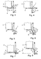
- Figs. 1 - 6 show an elevator with its car 2 stuck between floors at distance h from a landing.
- the car 2 is provided with horizontal guide tracks 5 secured under the floor of the car and a toe guard 1 is mounted to be supported by the guide tracks 5.
- the toe guard is in a stowaway position A under the floor, in an orientation parallel to the guide tracks 5, so it takes up only a small space in the vertical direction.
- the toe guard 1 comprises a movable panel 3, which consists of two panel parts telescopically connected together, i.e. a first panel part 10 and a second panel part 11.
- the panel Being guided and supported by the guide tracks 5, the panel is movable between a stowaway position A and an operative position B, which are shown in Figs. 1 and 3 .
- the panel parts 10 and 11 rest on the guide tracks in a substantially horizontal orientation under the car, where they can be locked in place by means of a locking device 4.
- the toe guard 1, supported by the guide tracks 5 has been drawn out onto the landing floor 6 and tilted to cover the gap 8 between the car sill 7 and the landing floor 6.
- the toe guard 1 can be locked to the door jambs 9 of the landing door by means of the locking device 4.
- the first panel part 10 can be moved along the guide tracks 5 between a drawn-out position, in which it is drawn out substantially onto the landing floor 6, and a stowed-away position under the car 2.
- the second panel part 11, being guided by the first panel part 10, is telescopically movable between a retracted extreme position and an extended extreme position.
- the first and second panel parts are disposed in a mutually nested and/or superposed relationship ( Fig. 3 ).
- the first and second panel parts are disposed substantially in a mutually adjacent relationship (see Figs. 2 , 6 , 10 ).
- the toe guard When the toe guard is moved from the stowaway position into the operative position, it assumes steplessly a suitable length between the aforesaid retracted extreme position and the aforesaid extended extreme position, depending in each case on the height position h of the elevator car having stopped between floors relative to the landing floor 6, as is also visualized in Figs. 7 and 8 .
- the toe guard 1 has been adapted to permit its use when the distance h between the car 2 and the landing floor 6 is of the order of about 50 mm at a minimum and about 1 m at a maximum.
- the toe guard 1 is only used when the car remains at a maximum distance of 800 mm above the landing floor. If the car is at a distance exceeding 800 mm above the landing floor, then the car must first be lowered to the level of the landing floor before the passengers are allowed to get out of the car.
- the elevator comprises a safety circuit which prevents elevator movement in an error situation.
- the toe guard 1 comprises a sensor 12 connected to the safety circuit.
- the sensor has been arranged to detect an error situation where the toe guard 1 is not in the stowaway position A.
- the sensor 12 may be e.g. a limit switch which is turned on by the panel parts 10, 11 when locked in the stowaway position shown in Fig. 3 .
- the toe guard 1 is used as illustrated in Figs. 3 and 6 , by releasing the locking device 4 by means of a tool 21.
- the panel parts 10 and 11 are pulled horizontally along the guide tracks 5 onto the landing floor 6.
- the panel parts 10 and 11 are tilted and the second panel part 11 is locked by means of the locking device 4 to the landing door jambs 9.
- the locking device 4 comprises a first locking bolt 15, which is arranged to be movable between a locking position with the bolt projecting from the first side edge 13 of the second panel part 11 in a substantially perpendicular direction and a releasing position with the bolt retracted into/onto/under the second panel part 11.
- the locking device 4 further comprises a second locking bolt 16, which is arranged to be movable between a locking position with the bolt projecting from the second side edge 14 of the second panel part 11 in a substantially perpendicular direction and a releasing position with the bolt retracted into/onto/under the second panel part 11.
- the actuating mechanism 17 comprises an axle pin 19 which is mounted on the second panel part 11 near its forward edge in about the middle region of the second panel part 11 so as to be rotatable about an axis perpendicular to the plane of the second panel part 11.
- the axle pin 19 comprises an engaging element 20 (e.g. a triangular notch) allowing the axle pin to be gripped with a tool 21 (e.g. a triangular key) to rotate it.
- a turnplate 22 is attached to the axle pin so as to be rotatable together with it.
- the first locking bolt 15 is at the first end of a first rod 23.
- the first rod 23 is pivotally joined at its second end to the turnplate at a distance from the axle pin 19.
- the second locking bolt 16 is at the first end of a second rod 24.
- the second rod 24 is pivotally joined at its second end to the turnplate 22 at a distance from the axle pin 19 on the opposite side relative to the pivotal joint of the second end of the first rod 23.
- the actuating mechanism 17 further comprises a spring 25 arranged to force the locking bolts 15, 16 towards the releasing position.
- the first panel part 10 comprises a rear edge 26, a third side edge 27 with a pin 28 fastened to it at a position near the rear edge, and a fourth side edge 29 with a pin 28 fastened to it at a position near the rear edge.
- the toe guard 1 is arranged to be supported by a pair of supporting members 30.
- Each supporting member 30 has a horizontal slot 31, through which the pin is adapted to extend.
- the slots 31 form the aforesaid guide tracks 5.
- the slot 31 has a downward part 32 into which the pin 28 falls when the first panel part 10 is in the drawn-out extreme position.
- the downward part 32 and the pin 28 together constitute a hinge about which the toe guard can be turned into an angle relative to the horizontal.
- the first panel part 10 is formed from sheet metal having a first edge bend 33, 34 at either side edge 27, 29.
- the second panel part 11 is formed from sheet metal having a second edge bend 35, 36 at either side edge 13, 14.
- the second panel part 11 is adapted to fit with a clearance in the space delimited by the first edge bends 33, 34.
Landscapes
- Cage And Drive Apparatuses For Elevators (AREA)
- Elevator Door Apparatuses (AREA)
Claims (11)
- Zehenschutz (1) für eine Aufzugskabine (2), welcher Zehenschutz ein bewegbares Panel (3) aufweist, das mit einer Sperrvorrichtung (4) versehen ist, ferner Führungsschienen (5), die unterhalb der Kabine (2) in einer im Wesentlichen horizontalen Orientierung montiert sind, welches Panel, wenn es durch die Führungsschienen (5) geführt und unterstützt ist, zwischen einer Versteck-Position (A) und einer Betriebsposition (B) bewegbar ist, in welcher Versteckposition (A) das Panel auf den Führungsschienen in einer im Wesentlichen horizontalen Orientierung unter der Kabine ruht und an Ort und Stelle mit Hilfe der Sperrvorrichtung sperrbar ist, und in welcher Betriebsposition (B) der Zehenschutz, unterstützt durch die Führungsschienen, aus dem Geschoss-Boden (6) herausgezogen ist und geneigt ist, um den Zwischenraum (8) zwischen der Kabinen-Einstiegskante (7) und dem Geschoss-Boden (6) zu überbrücken, und in welcher Betriebsposition der Zehenschutz an der Geschoss-Türenlaibung (9) mit Hilfe der Sperrvorrichtung (4) sperrbar ist, dadurch gekennzeichnet, dass das Panel (3) aufweist:- ein erstes Panelteil (10), das, wenn durch die Führungsschienen (5) geführt, im Wesentlichen zwischen einer herausgezogenen Position, bei der es aus dem Geschoss-Boden herausgezogen ist, und einer Versteckposition unter der Kabine bewegbar ist, und- ein zweites Panelteil (11), das, wenn durch das erste Panelteil (10) geführt, teleskopartig zwischen einer zurückgezogenen Extremposition, bei der das erste und zweite Panelteil in einer gegenseitig ineinander verschobenen und/oder übereinanderliegenden Beziehung angeordnet sind, und einer ausgedehnten Extremposition bewegbar ist, bei der das erste und zweite Panelteil im Wesentlichen in einer zueinander benachbarten Beziehung angeordnet sind.
- Zehenschutz nach Anspruch 1, dadurch gekennzeichnet, dass der Zehenschutz (1) dazu adaptiert ist, seine Verwendung zu ermöglichen, wenn der Abstand (h) zwischen der Kabine (2) und dem Geschossboden (6) in der Größenordnung von ca. 50 mm im Minimum und ca. 1 m im Maximum beträgt.
- Zehenschutz nach Anspruch 1, dadurch gekennzeichnet, dass der Aufzug einen Sicherheitskreis aufweist, der den Aufzug von einer Bewegung in einer Fehlsituation hindert; und dass der Zehenschutz einen Sensor (12) aufweist, der an den Sicherheitskreis angeschlossen und angeordnet ist, um eine Fehlsituation zu detektieren, bei der sich der Zehenschutz nicht in der Versteck-Position befindet.
- Zehenschutz nach einem der Ansprüche 1 - 3, dadurch gekennzeichnet, dass das zweite Panelteil (11) einen ersten Seitenrand (13) und einen zweiten Seitenrand (14) aufweist, die sich parallel zu den Führungsschienen erstrecken, und dass die Sperrvorrichtung aufweist:- einen ersten Sperrbolzen (15), der angeordnet ist, um zwischen einer Sperrposition, bei der der Bolzen aus dem ersten Seitenrand (13) in einer im Wesentlichen senkrechten Richtung hervorsteht, und einer Freigabeposition bewegbar ist, bei der der Bolzen in/auf/unter das zweite Panelteil (11) zurückgezogen ist,- einen zweiten Sperrbolzen (16), der angeordnet ist, um zwischen einer Sperrposition, bei der der Bolzen aus dem zweiten Seitenrand (14) in einer im Wesentlichen senkrechten Richtung hervorsteht, und einer Freigabeposition bewegbar ist, bei der der Bolzen in/auf/unter das zweite Panelteil (11) zurückgezogen ist,- einen Stellmechanismus (17) zum gleichzeitigen Bewegen des ersten Sperrbolzens (15) und des zweiten Sperrbolzens (16) zwischen der Sperrposition und der Freigabeposition.
- Zehenschutz nach Anspruch 4, dadurch gekennzeichnet, dass das zweite Panelteil (11) einen vorderen Rand (18) hat, der den in Richtung zum Geschoss orientierten Rand darstellt, und dass der Stellmechanismus (17) aufweist:- einen Achsstift (19), der an dem zweiten Panelteil (11) nahe dessen vorderen Randes (18) montiert ist, um so um eine Achse rotierbar zu sein, die senkrecht auf die Ebene des zweiten Panelteils steht, wobei der Achsstift ein Eingriffselement (20) aufweist, und wobei der Achsstift durch ein Werkzeug (21) zu dessen Rotation ergriffen werden kann,- eine Drehplatte (22), die an dem Achsstift (19) befestigt ist, um somit mit ihm zusammen rotierbar zu sein,- einen ersten Bolzen (23), an dessen erstem Ende der erste Sperrbolzen (15) ist, wobei der erste Bolzen drehbar an seinem zweiten Ende zur Drehplatte in einem Abstand vom Achsstift (19) gelagert ist, und- einen zweiten Bolzen (24), an dessen erstem Ende der zweite Sperrbolzen (16) ist, wobei der zweite Bolzen drehbar an dessen zweitem Ende an der Drehplatte (22) in einem Abstand von dem Achsstift (19) auf der gegenüberliegenden Seite relativ zu dem Drehlager des zweiten Endes des ersten Bolzens gelagert ist.
- Zehenschutz nach Anspruch 5, dadurch gekennzeichnet, dass das Eingriffselement (20) eine dreiecksförmige Kerbe ist, die zum Eingriff mit einem dreiecksförmigen Schlüssel (21) konzipiert ist.
- Zehenschutz nach Anspruch 5 oder 6, dadurch gekennzeichnet, dass der Stellmechanismus (17) eine Feder (25) aufweist, die zum Drängen der Sperrbolzen (15, 16) in Richtung zur Freigabeposition angeordnet ist.
- Zehenschutz nach einem der Ansprüche 6 - 7, dadurch gekennzeichnet, dass der Achsstift (19) in etwa im Mittelbereich des zweiten Panelteils (11) in unmittelbarer Nähe des vorderen Randes (18) angeordnet ist.
- Zehenschutz nach einem der Ansprüche 1 - 7, dadurch gekennzeichnet, dass das erste Panelteil (10) einen rückwärtigen Rand (26) aufweist, einen dritten Seitenrand (27) mit einem Stift (28), der darin in einer Position nahe des rückwärtigen Randes festgelegt ist, sowie einen vierten Seitenrand (29) mit einem Stift (28), der darin in einer Position nahe des rückwärtigen Randes festgelegt ist; und dass der Zehenschutz (1) angeordnet ist, um durch ein Paar von Tragelementen (30) unterstützt zu sein, wobei jedes der Tragelemente (30) einen horizontalen Schlitz (31) aufweist, durch den der Stift (28) sich zu erstrecken konzipiert ist, wobei die Schlitze (31) die zuvor erwähnten Führungsschienen (5) bilden.
- Zehenschutz nach Anspruch 9, dadurch gekennzeichnet, dass der Schlitz (31) an seinem Ende nahe der Kabinentür-Einstiegskante ein nach unten gerichtetes Teil (32) hat, in das der Stift (28) fällt, wenn sich das erste Panelteil in der herausgezogenen Position befindet, und welches Teil (32) zusammen mit dem Stift (28) eine Aufhängung bildet, um die der Zehenschutz (1) in einen Winkel relativ zu der Horizontalen drehbar ist.
- Zehenschutz nach einem der Ansprüche 1 - 10, dadurch gekennzeichnet, dass das erste Panelteil (10) aus dem Schichtmaterial gebildet ist, mit einer ersten Randbördelung (33, 34) an einem jeweiligen Seitenrand (27, 29), und dass das zweite Panelteil (11) von dem Schichtmaterial gebildet ist, mit einer zweiten Randbördelung (35, 36) an einem jeweiligen Seitenrand (13, 14), wobei das zweite Panelteil dazu konzipiert ist, mit einem Zwischenraum in dem Raum einzupassen, der durch die ersten Randbördelungen (33, 34) begrenzt ist.
Applications Claiming Priority (2)
| Application Number | Priority Date | Filing Date | Title |
|---|---|---|---|
| FI20061138A FI119021B (fi) | 2006-12-19 | 2006-12-19 | Varvassuojus hissin koria varten |
| PCT/FI2007/000279 WO2008074911A1 (en) | 2006-12-19 | 2007-11-28 | Toe guard for an elevator car |
Publications (3)
| Publication Number | Publication Date |
|---|---|
| EP2094597A1 EP2094597A1 (de) | 2009-09-02 |
| EP2094597A4 EP2094597A4 (de) | 2013-10-02 |
| EP2094597B1 true EP2094597B1 (de) | 2015-01-07 |
Family
ID=37623761
Family Applications (1)
| Application Number | Title | Priority Date | Filing Date |
|---|---|---|---|
| EP07858303.6A Not-in-force EP2094597B1 (de) | 2006-12-19 | 2007-11-28 | Zehenschutz für eine aufzugskabine |
Country Status (6)
| Country | Link |
|---|---|
| US (1) | US8356699B2 (de) |
| EP (1) | EP2094597B1 (de) |
| CN (1) | CN101558004B (de) |
| ES (1) | ES2528445T3 (de) |
| FI (1) | FI119021B (de) |
| WO (1) | WO2008074911A1 (de) |
Cited By (2)
| Publication number | Priority date | Publication date | Assignee | Title |
|---|---|---|---|---|
| US11136222B2 (en) | 2018-07-26 | 2021-10-05 | Otis Elevator Company | Elevator car apron |
| US11161716B2 (en) | 2018-02-23 | 2021-11-02 | Otis Elevator Company | Elevator car toe guard system |
Families Citing this family (19)
| Publication number | Priority date | Publication date | Assignee | Title |
|---|---|---|---|---|
| CN101985340B (zh) * | 2010-09-30 | 2013-06-26 | 日立电梯(中国)有限公司 | 用于减小电梯厅门地坎与轿门地坎间隙的装置及方法 |
| US8469155B2 (en) * | 2011-02-16 | 2013-06-25 | Vertical Motion Innovations, Llc | Elevator life safety gate |
| JP5796124B2 (ja) * | 2011-03-22 | 2015-10-21 | オーチス エレベータ カンパニーOtis Elevator Company | エレベータ装置のトーガードアセンブリ |
| CN103443011B (zh) * | 2011-04-05 | 2015-12-16 | 奥的斯电梯公司 | 用于电梯系统的护脚板组件 |
| EP3003947B1 (de) * | 2013-06-05 | 2018-10-03 | Otis Elevator Company | Einziehbare zehenschutzanordnung für ein aufzugssystem |
| CN104030134B (zh) * | 2014-06-25 | 2016-05-18 | 河南科技大学 | 一种安全电梯轿厢 |
| CN104030135B (zh) * | 2014-06-25 | 2016-05-18 | 河南科技大学 | 具有安全防护功能的电梯轿厢 |
| CN104249961A (zh) * | 2014-10-12 | 2014-12-31 | 邓勤 | 电梯轿厢升降安全支架 |
| CN104261221A (zh) * | 2014-10-12 | 2015-01-07 | 黄东连 | 电梯轿厢升降安全冂形框 |
| CN106477431B (zh) * | 2015-09-01 | 2020-01-21 | 奥的斯电梯公司 | 电梯轿厢的轿厢室隔离 |
| US10112803B2 (en) * | 2016-04-01 | 2018-10-30 | Otis Elevator Company | Protection assembly for elevator braking assembly speed sensing device and method |
| KR101939656B1 (ko) * | 2017-06-22 | 2019-01-17 | 주식회사 더원 | 엘리베이터용 에이프런 구조체 |
| GR1009417B (el) * | 2017-09-12 | 2018-12-14 | Κλεμαν Ελλας-Kleeman Hellas Α.Β.Ε.Ε. Για Μηχανολογικες Κατασκευες Α.Ε. | Πτυσσομενη ποδια θαλαμου ανελκυστηρα απο ευκαμπτο υλικο με μοχλοβραχιονες στηριξης και ελατηρια αερος |
| CN110407065B (zh) * | 2018-04-28 | 2022-04-29 | 中国建筑科学研究院有限公司建筑机械化研究分院 | 护脚板高度可调整装置及电梯装置系统 |
| EP3608282B1 (de) | 2018-08-10 | 2022-06-22 | Otis Elevator Company | Aufzugskabinenschürze |
| CN114531871B (zh) * | 2019-09-30 | 2023-11-17 | 因温特奥股份公司 | 电梯设备 |
| CN113636436A (zh) * | 2021-08-17 | 2021-11-12 | 中建科工集团有限公司 | 一种建筑施工电梯用自动收缩踏板装置 |
| CN114261870A (zh) * | 2021-12-15 | 2022-04-01 | 中国建筑第五工程局有限公司 | 一种用于人货梯的防冲出装置和人货梯 |
| EP4466212A1 (de) * | 2022-01-20 | 2024-11-27 | KONE Corporation | Schürzenvorrichtung, aufzugskabine und verfahren zum schutz vor dem fallen in den aufzugsschacht |
Family Cites Families (15)
| Publication number | Priority date | Publication date | Assignee | Title |
|---|---|---|---|---|
| US4251179A (en) * | 1978-03-13 | 1981-02-17 | Transportation Design & Technology, Inc. | Wheelchair lift |
| US4302145A (en) * | 1979-11-19 | 1981-11-24 | The Peelle Company | Automatic drawbridge for elevator |
| US5832555A (en) * | 1995-02-27 | 1998-11-10 | Ricon Corporation | Compact moveable ramp assembly |
| JPH1017252A (ja) * | 1996-06-28 | 1998-01-20 | Hitachi Building Syst Co Ltd | エレベータの乗りかご |
| US6095288A (en) * | 1999-04-22 | 2000-08-01 | Otis Elevator Company | Pit-less elevator |
| JP2001240332A (ja) * | 2000-02-28 | 2001-09-04 | Hitachi Building Systems Co Ltd | エレベーターの閉じ込め救出装置 |
| IT251255Y1 (it) * | 2000-07-28 | 2003-11-19 | Selcom Spa | Paramento mobile in cabina di ascensore od elevatore |
| FI20002743A7 (fi) * | 2000-12-14 | 2002-06-15 | Kone Corp | Jalkasuojus |
| JP2002205881A (ja) * | 2001-01-10 | 2002-07-23 | Mitsubishi Electric Corp | エレベーター装置 |
| AU2002241939A1 (en) * | 2001-01-31 | 2002-08-12 | Otis Elevator Company | Moveable toe guard assembly for elevators |
| DE10115990C1 (de) * | 2001-03-30 | 2002-10-10 | Reinhard Muth | Sicherheitssystem für einen Fahrstuhl |
| JP2005145610A (ja) * | 2003-11-13 | 2005-06-09 | Mitsubishi Electric Corp | エレベータのエプロン装置 |
| FI118220B (fi) * | 2004-06-07 | 2007-08-31 | Kone Corp | Hissin oviaukon turvajärjestely |
| CN2820794Y (zh) * | 2005-08-31 | 2006-09-27 | 湖南海诺电梯有限公司 | 垂直升降电梯轿厢电动护脚板装置 |
| ITMI20062019A1 (it) * | 2006-10-20 | 2008-04-21 | Centiducati S P A | Grembiule pieghevole di cabina per un impianto di ascensore |
-
2006
- 2006-12-19 FI FI20061138A patent/FI119021B/fi not_active IP Right Cessation
-
2007
- 2007-11-28 EP EP07858303.6A patent/EP2094597B1/de not_active Not-in-force
- 2007-11-28 ES ES07858303.6T patent/ES2528445T3/es active Active
- 2007-11-28 WO PCT/FI2007/000279 patent/WO2008074911A1/en not_active Ceased
- 2007-11-28 CN CN200780046256.4A patent/CN101558004B/zh not_active Expired - Fee Related
-
2009
- 2009-06-18 US US12/487,062 patent/US8356699B2/en not_active Expired - Fee Related
Cited By (2)
| Publication number | Priority date | Publication date | Assignee | Title |
|---|---|---|---|---|
| US11161716B2 (en) | 2018-02-23 | 2021-11-02 | Otis Elevator Company | Elevator car toe guard system |
| US11136222B2 (en) | 2018-07-26 | 2021-10-05 | Otis Elevator Company | Elevator car apron |
Also Published As
| Publication number | Publication date |
|---|---|
| EP2094597A4 (de) | 2013-10-02 |
| FI119021B (fi) | 2008-06-30 |
| FI20061138A0 (fi) | 2006-12-19 |
| WO2008074911A1 (en) | 2008-06-26 |
| US8356699B2 (en) | 2013-01-22 |
| US20090277725A1 (en) | 2009-11-12 |
| CN101558004B (zh) | 2014-08-20 |
| ES2528445T3 (es) | 2015-02-10 |
| EP2094597A1 (de) | 2009-09-02 |
| CN101558004A (zh) | 2009-10-14 |
Similar Documents
| Publication | Publication Date | Title |
|---|---|---|
| EP2094597B1 (de) | Zehenschutz für eine aufzugskabine | |
| US8479889B2 (en) | Buffer arrangement and buffer stop of an elevator | |
| EP2688826B1 (de) | Schürzenanordnung für ein aufzugssystem | |
| EP2694418B1 (de) | Schürzenanordnung für ein aufzugssystem | |
| US7281609B2 (en) | Elevator inspection safety devices | |
| US20140255138A1 (en) | Ramp System for Installation in a Vehicle | |
| US20190256322A1 (en) | Elevator safety arrangement and elevator | |
| US20210061616A1 (en) | Low overhead compensatory measure | |
| IL215654A (en) | Folding apron for elevator with moving floor in pit with reduced depth | |
| US20130025975A1 (en) | Retractable Stop for Low Overhead Elevators | |
| CN112088118B (zh) | 用于轨道车辆的驾驶台的模块化的脚踏板 | |
| JP5091498B2 (ja) | チルト式キャビンのストッパ構造 | |
| JP6157962B2 (ja) | エレベータ装置 | |
| EP1781563B1 (de) | Aufzugsanordnung | |
| JP2021187643A (ja) | 乗客コンベアのマンホール蓋及び乗客コンベア | |
| JP6249288B2 (ja) | エレベータのドア開閉装置 | |
| KR20060080587A (ko) | 엘리베이터 검사 안전 장치 |
Legal Events
| Date | Code | Title | Description |
|---|---|---|---|
| PUAI | Public reference made under article 153(3) epc to a published international application that has entered the european phase |
Free format text: ORIGINAL CODE: 0009012 |
|
| 17P | Request for examination filed |
Effective date: 20090515 |
|
| AK | Designated contracting states |
Kind code of ref document: A1 Designated state(s): AT BE BG CH CY CZ DE DK EE ES FI FR GB GR HU IE IS IT LI LT LU LV MC MT NL PL PT RO SE SI SK TR |
|
| DAX | Request for extension of the european patent (deleted) | ||
| A4 | Supplementary search report drawn up and despatched |
Effective date: 20130830 |
|
| RIC1 | Information provided on ipc code assigned before grant |
Ipc: B66B 13/28 20060101AFI20130826BHEP |
|
| GRAP | Despatch of communication of intention to grant a patent |
Free format text: ORIGINAL CODE: EPIDOSNIGR1 |
|
| INTG | Intention to grant announced |
Effective date: 20140929 |
|
| GRAS | Grant fee paid |
Free format text: ORIGINAL CODE: EPIDOSNIGR3 |
|
| GRAA | (expected) grant |
Free format text: ORIGINAL CODE: 0009210 |
|
| AK | Designated contracting states |
Kind code of ref document: B1 Designated state(s): AT BE BG CH CY CZ DE DK EE ES FI FR GB GR HU IE IS IT LI LT LU LV MC MT NL PL PT RO SE SI SK TR |
|
| REG | Reference to a national code |
Ref country code: GB Ref legal event code: FG4D |
|
| REG | Reference to a national code |
Ref country code: CH Ref legal event code: EP |
|
| REG | Reference to a national code |
Ref country code: IE Ref legal event code: FG4D |
|
| REG | Reference to a national code |
Ref country code: ES Ref legal event code: FG2A Ref document number: 2528445 Country of ref document: ES Kind code of ref document: T3 Effective date: 20150210 |
|
| REG | Reference to a national code |
Ref country code: AT Ref legal event code: REF Ref document number: 705546 Country of ref document: AT Kind code of ref document: T Effective date: 20150215 |
|
| REG | Reference to a national code |
Ref country code: DE Ref legal event code: R096 Ref document number: 602007040006 Country of ref document: DE Effective date: 20150226 |
|
| REG | Reference to a national code |
Ref country code: NL Ref legal event code: VDEP Effective date: 20150107 |
|
| REG | Reference to a national code |
Ref country code: AT Ref legal event code: MK05 Ref document number: 705546 Country of ref document: AT Kind code of ref document: T Effective date: 20150107 |
|
| REG | Reference to a national code |
Ref country code: LT Ref legal event code: MG4D |
|
| PG25 | Lapsed in a contracting state [announced via postgrant information from national office to epo] |
Ref country code: FI Free format text: LAPSE BECAUSE OF FAILURE TO SUBMIT A TRANSLATION OF THE DESCRIPTION OR TO PAY THE FEE WITHIN THE PRESCRIBED TIME-LIMIT Effective date: 20150107 Ref country code: LT Free format text: LAPSE BECAUSE OF FAILURE TO SUBMIT A TRANSLATION OF THE DESCRIPTION OR TO PAY THE FEE WITHIN THE PRESCRIBED TIME-LIMIT Effective date: 20150107 Ref country code: SE Free format text: LAPSE BECAUSE OF FAILURE TO SUBMIT A TRANSLATION OF THE DESCRIPTION OR TO PAY THE FEE WITHIN THE PRESCRIBED TIME-LIMIT Effective date: 20150107 Ref country code: BG Free format text: LAPSE BECAUSE OF FAILURE TO SUBMIT A TRANSLATION OF THE DESCRIPTION OR TO PAY THE FEE WITHIN THE PRESCRIBED TIME-LIMIT Effective date: 20150407 |
|
| PG25 | Lapsed in a contracting state [announced via postgrant information from national office to epo] |
Ref country code: NL Free format text: LAPSE BECAUSE OF FAILURE TO SUBMIT A TRANSLATION OF THE DESCRIPTION OR TO PAY THE FEE WITHIN THE PRESCRIBED TIME-LIMIT Effective date: 20150107 Ref country code: IS Free format text: LAPSE BECAUSE OF FAILURE TO SUBMIT A TRANSLATION OF THE DESCRIPTION OR TO PAY THE FEE WITHIN THE PRESCRIBED TIME-LIMIT Effective date: 20150507 Ref country code: GR Free format text: LAPSE BECAUSE OF FAILURE TO SUBMIT A TRANSLATION OF THE DESCRIPTION OR TO PAY THE FEE WITHIN THE PRESCRIBED TIME-LIMIT Effective date: 20150408 Ref country code: PL Free format text: LAPSE BECAUSE OF FAILURE TO SUBMIT A TRANSLATION OF THE DESCRIPTION OR TO PAY THE FEE WITHIN THE PRESCRIBED TIME-LIMIT Effective date: 20150107 Ref country code: AT Free format text: LAPSE BECAUSE OF FAILURE TO SUBMIT A TRANSLATION OF THE DESCRIPTION OR TO PAY THE FEE WITHIN THE PRESCRIBED TIME-LIMIT Effective date: 20150107 Ref country code: LV Free format text: LAPSE BECAUSE OF FAILURE TO SUBMIT A TRANSLATION OF THE DESCRIPTION OR TO PAY THE FEE WITHIN THE PRESCRIBED TIME-LIMIT Effective date: 20150107 |
|
| REG | Reference to a national code |
Ref country code: DE Ref legal event code: R097 Ref document number: 602007040006 Country of ref document: DE |
|
| PG25 | Lapsed in a contracting state [announced via postgrant information from national office to epo] |
Ref country code: SK Free format text: LAPSE BECAUSE OF FAILURE TO SUBMIT A TRANSLATION OF THE DESCRIPTION OR TO PAY THE FEE WITHIN THE PRESCRIBED TIME-LIMIT Effective date: 20150107 Ref country code: DK Free format text: LAPSE BECAUSE OF FAILURE TO SUBMIT A TRANSLATION OF THE DESCRIPTION OR TO PAY THE FEE WITHIN THE PRESCRIBED TIME-LIMIT Effective date: 20150107 Ref country code: EE Free format text: LAPSE BECAUSE OF FAILURE TO SUBMIT A TRANSLATION OF THE DESCRIPTION OR TO PAY THE FEE WITHIN THE PRESCRIBED TIME-LIMIT Effective date: 20150107 Ref country code: RO Free format text: LAPSE BECAUSE OF FAILURE TO SUBMIT A TRANSLATION OF THE DESCRIPTION OR TO PAY THE FEE WITHIN THE PRESCRIBED TIME-LIMIT Effective date: 20150107 Ref country code: CZ Free format text: LAPSE BECAUSE OF FAILURE TO SUBMIT A TRANSLATION OF THE DESCRIPTION OR TO PAY THE FEE WITHIN THE PRESCRIBED TIME-LIMIT Effective date: 20150107 |
|
| PLBE | No opposition filed within time limit |
Free format text: ORIGINAL CODE: 0009261 |
|
| STAA | Information on the status of an ep patent application or granted ep patent |
Free format text: STATUS: NO OPPOSITION FILED WITHIN TIME LIMIT |
|
| REG | Reference to a national code |
Ref country code: FR Ref legal event code: PLFP Year of fee payment: 9 |
|
| 26N | No opposition filed |
Effective date: 20151008 |
|
| PG25 | Lapsed in a contracting state [announced via postgrant information from national office to epo] |
Ref country code: IT Free format text: LAPSE BECAUSE OF FAILURE TO SUBMIT A TRANSLATION OF THE DESCRIPTION OR TO PAY THE FEE WITHIN THE PRESCRIBED TIME-LIMIT Effective date: 20150107 |
|
| PG25 | Lapsed in a contracting state [announced via postgrant information from national office to epo] |
Ref country code: SI Free format text: LAPSE BECAUSE OF FAILURE TO SUBMIT A TRANSLATION OF THE DESCRIPTION OR TO PAY THE FEE WITHIN THE PRESCRIBED TIME-LIMIT Effective date: 20150107 |
|
| PG25 | Lapsed in a contracting state [announced via postgrant information from national office to epo] |
Ref country code: BE Free format text: LAPSE BECAUSE OF FAILURE TO SUBMIT A TRANSLATION OF THE DESCRIPTION OR TO PAY THE FEE WITHIN THE PRESCRIBED TIME-LIMIT Effective date: 20150107 |
|
| PG25 | Lapsed in a contracting state [announced via postgrant information from national office to epo] |
Ref country code: LU Free format text: LAPSE BECAUSE OF FAILURE TO SUBMIT A TRANSLATION OF THE DESCRIPTION OR TO PAY THE FEE WITHIN THE PRESCRIBED TIME-LIMIT Effective date: 20151128 Ref country code: MC Free format text: LAPSE BECAUSE OF FAILURE TO SUBMIT A TRANSLATION OF THE DESCRIPTION OR TO PAY THE FEE WITHIN THE PRESCRIBED TIME-LIMIT Effective date: 20150107 |
|
| REG | Reference to a national code |
Ref country code: CH Ref legal event code: PL |
|
| PG25 | Lapsed in a contracting state [announced via postgrant information from national office to epo] |
Ref country code: LI Free format text: LAPSE BECAUSE OF NON-PAYMENT OF DUE FEES Effective date: 20151130 Ref country code: CH Free format text: LAPSE BECAUSE OF NON-PAYMENT OF DUE FEES Effective date: 20151130 |
|
| REG | Reference to a national code |
Ref country code: IE Ref legal event code: MM4A |
|
| PG25 | Lapsed in a contracting state [announced via postgrant information from national office to epo] |
Ref country code: IE Free format text: LAPSE BECAUSE OF NON-PAYMENT OF DUE FEES Effective date: 20151128 |
|
| REG | Reference to a national code |
Ref country code: FR Ref legal event code: PLFP Year of fee payment: 10 |
|
| PG25 | Lapsed in a contracting state [announced via postgrant information from national office to epo] |
Ref country code: HU Free format text: LAPSE BECAUSE OF FAILURE TO SUBMIT A TRANSLATION OF THE DESCRIPTION OR TO PAY THE FEE WITHIN THE PRESCRIBED TIME-LIMIT; INVALID AB INITIO Effective date: 20071128 |
|
| PG25 | Lapsed in a contracting state [announced via postgrant information from national office to epo] |
Ref country code: CY Free format text: LAPSE BECAUSE OF FAILURE TO SUBMIT A TRANSLATION OF THE DESCRIPTION OR TO PAY THE FEE WITHIN THE PRESCRIBED TIME-LIMIT Effective date: 20150107 |
|
| PG25 | Lapsed in a contracting state [announced via postgrant information from national office to epo] |
Ref country code: TR Free format text: LAPSE BECAUSE OF FAILURE TO SUBMIT A TRANSLATION OF THE DESCRIPTION OR TO PAY THE FEE WITHIN THE PRESCRIBED TIME-LIMIT Effective date: 20150107 Ref country code: MT Free format text: LAPSE BECAUSE OF FAILURE TO SUBMIT A TRANSLATION OF THE DESCRIPTION OR TO PAY THE FEE WITHIN THE PRESCRIBED TIME-LIMIT Effective date: 20150107 |
|
| REG | Reference to a national code |
Ref country code: FR Ref legal event code: PLFP Year of fee payment: 11 |
|
| PG25 | Lapsed in a contracting state [announced via postgrant information from national office to epo] |
Ref country code: PT Free format text: LAPSE BECAUSE OF FAILURE TO SUBMIT A TRANSLATION OF THE DESCRIPTION OR TO PAY THE FEE WITHIN THE PRESCRIBED TIME-LIMIT Effective date: 20150107 |
|
| PGFP | Annual fee paid to national office [announced via postgrant information from national office to epo] |
Ref country code: GB Payment date: 20201119 Year of fee payment: 14 Ref country code: DE Payment date: 20201119 Year of fee payment: 14 Ref country code: FR Payment date: 20201120 Year of fee payment: 14 |
|
| PGFP | Annual fee paid to national office [announced via postgrant information from national office to epo] |
Ref country code: ES Payment date: 20210122 Year of fee payment: 14 |
|
| REG | Reference to a national code |
Ref country code: DE Ref legal event code: R119 Ref document number: 602007040006 Country of ref document: DE |
|
| GBPC | Gb: european patent ceased through non-payment of renewal fee |
Effective date: 20211128 |
|
| PG25 | Lapsed in a contracting state [announced via postgrant information from national office to epo] |
Ref country code: GB Free format text: LAPSE BECAUSE OF NON-PAYMENT OF DUE FEES Effective date: 20211128 Ref country code: DE Free format text: LAPSE BECAUSE OF NON-PAYMENT OF DUE FEES Effective date: 20220601 |
|
| PG25 | Lapsed in a contracting state [announced via postgrant information from national office to epo] |
Ref country code: FR Free format text: LAPSE BECAUSE OF NON-PAYMENT OF DUE FEES Effective date: 20211130 |
|
| REG | Reference to a national code |
Ref country code: ES Ref legal event code: FD2A Effective date: 20230217 |
|
| PG25 | Lapsed in a contracting state [announced via postgrant information from national office to epo] |
Ref country code: ES Free format text: LAPSE BECAUSE OF NON-PAYMENT OF DUE FEES Effective date: 20211129 |