EP2094938B1 - Distortion compensation for rod piston bore in subsurface safety valves - Google Patents
Distortion compensation for rod piston bore in subsurface safety valves Download PDFInfo
- Publication number
- EP2094938B1 EP2094938B1 EP07863931.7A EP07863931A EP2094938B1 EP 2094938 B1 EP2094938 B1 EP 2094938B1 EP 07863931 A EP07863931 A EP 07863931A EP 2094938 B1 EP2094938 B1 EP 2094938B1
- Authority
- EP
- European Patent Office
- Prior art keywords
- bore
- piston
- piston bore
- valve
- additional blind
- Prior art date
- Legal status (The legal status is an assumption and is not a legal conclusion. Google has not performed a legal analysis and makes no representation as to the accuracy of the status listed.)
- Active
Links
Images

Classifications
-
- E—FIXED CONSTRUCTIONS
- E21—EARTH OR ROCK DRILLING; MINING
- E21B—EARTH OR ROCK DRILLING; OBTAINING OIL, GAS, WATER, SOLUBLE OR MELTABLE MATERIALS OR A SLURRY OF MINERALS FROM WELLS
- E21B34/00—Valve arrangements for boreholes or wells
- E21B34/06—Valve arrangements for boreholes or wells in wells
- E21B34/10—Valve arrangements for boreholes or wells in wells operated by control fluid supplied from outside the borehole
Definitions
- the field of this invention is downhole subsurface safety valves that operate a valve member with control line pressure delivered into a piston bore.
- Sub-surface safety valves are used in production tubing to control the well and to close it off to prevent a blowout.
- these valves have a disc shaped valve member that is known as a flapper.
- the flapper pivots over 90 degrees between an open and a closed position.
- a shiftable tube known as a flow tube is movable between two positions. When shifted down it engages the flapper to rotate it 90 degrees and keeps advancing as the flapper is moved into a position behind the flow tube. In this position the SSSV is open.
- a closure spring which was compressed as the flow tube opened the SSSV is used to return the flow tube to the original position. When the flow tube rises a pivot spring on the flapper urges it up against a seal surface to close off the production tubing.
- a control line is run adjacent the production tubing from the surface to a piston bore in the SSSV.
- pistons that can be used and they are generally linked to the flow tube such that applied and retained pressure in the control line acts on a piston that is linked to the flow tube to hold the flow tube down against a closure spring and keep the flapper in the open position.
- One common piston type is a rod piston called that because of its shape.
- Other piston types can have an annular shape.
- the rod piston sits in an elongated bore in a main housing component of the SSSV that usually terminates in a two step male thread also known as a pin.
- the pin is made up to a female thread called a box to fully assemble the SSSV.
- Injection bores in SSSVs have been used to deliver chemicals behind the flow tube as illustrated in U.S. Pat. No. 6,148,920 and US published application US 2005/0098210 .
- Also relevant to SSSV in general are U.S. Pat. Nos. 4,042,023 ; 4,399,871 ; 4,562854 ; 4,565,215 ; 5,718,289 and 6,148,920 and US application 2004/0040718 .
- US Patent Re. 32,390 describes a hydraulic actuating means for actuating a subsurface well safety valve which avoids the use of elastomer seals and can be used in both high and low pressure and high and low temperature applications and in the presence of corrosive fluids and gases.
- a piston is disposed in a sleeve that is disposed in a piston bore.
- the bore can distort but the sleeve within will not distort to the point of losing sealing pressure around the piston.
- additional bore or bores are provided adjacent the piston bore to make the pin end of the connection for the valve housing more uniform in the region of the piston bore so that pressure loading does not result in sufficient distortion of the piston bore to lose the piston sealing relation in its bore.
- FIG. 3 shows a section through a prior art SSSV showing the upper body 10 and a connection 12 for a control line from the surface (not shown). At the lower end is a two step male pin thread 14.
- a piston bore 16 Running through the wall of the upper body is a piston bore 16. Residing within this bore but not shown is a piston that is responsive to pressure application and removal as described above. Looking at the section view of FIG. 4 the piston bore 16 is located with respect to the longitudinal axis 19.
- FIGS 5-8 illustrate two solutions to this problem.
- FIGS. 5-6 there are additional blind bores 18 that are preferably parallel to piston bore 16.
- the additional holes 18 are uniformly spaced about the circumference starting from one side of the piston bore 16 and going all the way around to the other side of the piston bore 16 to distribute and minimize the distortion in each of the bores including the piston bore 16.
- FIGS. 7-8 illustrate a variation where there are fewer blind bores 20 but these holes are disposed close to piston bore 16 and preferably on both sides of piston bore 16 within a 90 degree arc.
- the major change in section is moved to the outer holes and away from the piston bore 16 the intent being to concentrate the stresses and thus the distortion at these outer holes and not at the piston bore 16 thus reducing the distortion at the piston bore 16.
- FIG. 6 represents the more comprehensive solution of sharing the stress from internal pressurization. It is more costly to produce since more blind bores 18 are used than in the FIG. 8 alternative using blind bores 20 despite the fact that the depth of fewer bores is preferably greater than the depth of an array using more blind bores. While the solution which seeks to divert the major portion of the total distortion to the outer holes on each side of the piston bore 16 is considered less effective in reducing the distortion in bore 16 than the solution which seeks to distribute the distortion among the many holes, the economics of using fewer holes is self evident and this second solution is also effective in reducing the distortion in piston bore 16.
- Computer controlled milling machines can be employed to produce many variations in number, depth, spacing, shape and angular orientation of the blind bores.
- the enhanced performance can be predicted in advance using known finite element method analysis.
- the proposed solution encompasses variation of the bore diameter with the larger diameter bores preferably closer to the piston bore 16. While the longitudinal axes of the blind bores are preferably parallel, variations are envisioned where some skewing of the longitudinal axes is envisioned with offsets in the order of 15 degrees or less from adjacent blind bores or of all the blind bores with respect to the longitudinal axis 18 either in the same orientation or differing orientations. For example, the longitudinal axes of all the blind bores can parallel to each other while at the same time skewed with respect to axis 18. The most economical design to machine would be the fewest number of blind bores parallel to each other and to axis 18. Bores can have identical or varying depths.
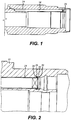
- FIGS. 1-2 illustrate another solution to the same problem.
- the piston bore 16 has an internal sleeve 24 in which the piston (not shown) travels back and forth.
- a seal 26 held in a groove 28 in housing 10 prevents pressure loss around the outside of sleeve 24.
- Sleeve 24 is inserted through the lower end of bore 16 and slides in because there is a clearance between its outside dimension and the bore dimension of piston bore 16. The seal 26 spans this clearance to seal it off.
- sleeve 24 can be pressed in for no clearance and the elimination of seal 26.
- a snap ring or other known fastener equivalent 30 is installed in a groove 32 in bore 16 to keep the sleeve 24 from shifting longitudinally.
- the objective here is to allow the piston bore 16 to distort while the sleeve 24 remains unaffected due to the clearance between them.
- FIGS. 1-2 can be used with the solution in FIGS. 6 or 8 or separately.
- the desired result in any case is to maintain sealing integrity of the seal around the piston that operates the flow tube in a SSSV or in other applications with high internal working pressures exceeding 20,000 PSI (138 MPa) where housings have piston bores regardless of the nature of the downhole device.
Landscapes
- Geology (AREA)
- Life Sciences & Earth Sciences (AREA)
- Engineering & Computer Science (AREA)
- Mining & Mineral Resources (AREA)
- Environmental & Geological Engineering (AREA)
- Fluid Mechanics (AREA)
- Physics & Mathematics (AREA)
- General Life Sciences & Earth Sciences (AREA)
- Geochemistry & Mineralogy (AREA)
- Safety Valves (AREA)
- Actuator (AREA)
- Lift Valve (AREA)
- Control Of Fluid Pressure (AREA)
- Fluid-Damping Devices (AREA)
Applications Claiming Priority (2)
| Application Number | Priority Date | Filing Date | Title |
|---|---|---|---|
| US11/595,591 US7699108B2 (en) | 2006-11-13 | 2006-11-13 | Distortion compensation for rod piston bore in subsurface safety valves |
| PCT/US2007/083700 WO2008060889A1 (en) | 2006-11-10 | 2007-11-06 | Distortion compensation for rod piston bore in subsurface safety valves |
Publications (2)
| Publication Number | Publication Date |
|---|---|
| EP2094938A1 EP2094938A1 (en) | 2009-09-02 |
| EP2094938B1 true EP2094938B1 (en) | 2020-01-08 |
Family
ID=39203266
Family Applications (1)
| Application Number | Title | Priority Date | Filing Date |
|---|---|---|---|
| EP07863931.7A Active EP2094938B1 (en) | 2006-11-13 | 2007-11-06 | Distortion compensation for rod piston bore in subsurface safety valves |
Country Status (8)
| Country | Link |
|---|---|
| US (2) | US7699108B2 (pt) |
| EP (1) | EP2094938B1 (pt) |
| CN (1) | CN101657604B (pt) |
| AU (1) | AU2007319495B2 (pt) |
| BR (1) | BRPI0718685B1 (pt) |
| NO (1) | NO344904B1 (pt) |
| RU (1) | RU2456432C2 (pt) |
| WO (1) | WO2008060889A1 (pt) |
Families Citing this family (8)
| Publication number | Priority date | Publication date | Assignee | Title |
|---|---|---|---|---|
| CN102971482B (zh) * | 2010-03-19 | 2015-07-15 | 诺伊蒂克技术股份有限公司 | 套管填充流体管理装置 |
| US9103185B2 (en) | 2011-02-10 | 2015-08-11 | Schlumberger Technology Corporation | Valve with removable component |
| US8668014B2 (en) * | 2011-02-14 | 2014-03-11 | Tejas Research & Engineering, Llc | Subsurface safety valve for high temperature and high pressure wells |
| US8857785B2 (en) | 2011-02-23 | 2014-10-14 | Baker Hughes Incorporated | Thermo-hydraulically actuated process control valve |
| US8967280B2 (en) | 2011-05-03 | 2015-03-03 | Baker Hughes Incorporated | Locking assembly for mechanically set packer |
| GB2499260B (en) * | 2012-02-13 | 2017-09-06 | Weatherford Tech Holdings Llc | Device and method for use in controlling fluid flow |
| US10914127B2 (en) | 2019-02-08 | 2021-02-09 | Peter J. Fay | Side pocket mandrel with enhanced pressure rating |
| US11788381B2 (en) * | 2020-06-22 | 2023-10-17 | Petróleo Brasileiro S.A.—Petrobrás | Mandril assembly for chemical injection in oil wells |
Family Cites Families (63)
| Publication number | Priority date | Publication date | Assignee | Title |
|---|---|---|---|---|
| GB1478206A (en) * | 1974-09-12 | 1977-06-29 | Weatherford Oil Tool | Control line positioning device for use in wells |
| US3971438A (en) | 1975-03-03 | 1976-07-27 | Baker Oil Tools, Inc. | Wireline safety valve with split ball |
| US4069834A (en) | 1976-04-26 | 1978-01-24 | Baker Cac, Inc. | Thermal safety valve |
| US4103744A (en) | 1977-08-04 | 1978-08-01 | Baker International Corporation | Safety valve and ball type equalizing valve |
| US4202368A (en) | 1978-03-13 | 1980-05-13 | Baker Cac, Inc. | Safety valve or blowout preventer for use in a fluid transmission conduit |
| SU883342A1 (ru) * | 1980-03-28 | 1981-11-23 | Производственное Объединение "Нижневартовскнефтегаз" | Забойный клапан-отсекатель дл насосной эксплуатации скважин |
| US4565215A (en) * | 1980-07-16 | 1986-01-21 | Cummings Leslie L | Chemical injection valve |
| US4478288A (en) | 1981-10-02 | 1984-10-23 | Baker International Corporation | Apparatus with annulus safety valve for through tubing injection and method of use |
| US4399871A (en) * | 1981-12-16 | 1983-08-23 | Otis Engineering Corporation | Chemical injection valve with openable bypass |
| US4427071A (en) | 1982-02-18 | 1984-01-24 | Baker Oil Tools, Inc. | Flapper type safety valve for subterranean wells |
| US4415036A (en) | 1982-02-22 | 1983-11-15 | Baker Oil Tools, Inc. | Pressure equalizing flapper type safety valve for subterranean wells |
| US4457376A (en) | 1982-05-17 | 1984-07-03 | Baker Oil Tools, Inc. | Flapper type safety valve for subterranean wells |
| USRE32390E (en) * | 1982-06-01 | 1987-04-07 | Camco, Incorporated | Hydraulic actuating means for subsurface safety valve |
| US4446922A (en) | 1982-06-16 | 1984-05-08 | Baker Oil Tools, Inc. | Adjustable safety valve |
| US4467870A (en) * | 1982-07-06 | 1984-08-28 | Baker Oil Tools, Inc. | Fluid pressure actuator for subterranean well apparatus |
| US4467867A (en) | 1982-07-06 | 1984-08-28 | Baker Oil Tools, Inc. | Subterranean well safety valve with reference pressure chamber |
| US4503913A (en) | 1983-07-18 | 1985-03-12 | Baker Oil Tools, Inc. | Subsurface well safety valve |
| US4562854A (en) * | 1984-09-27 | 1986-01-07 | Camco, Incorporated | Piston actuated chemical injection valve |
| CH666483A5 (de) * | 1985-01-16 | 1988-07-29 | Lonza Ag | Verfahren zur herstellung von thiotetronsaeure. |
| US4669547A (en) * | 1985-03-11 | 1987-06-02 | Camco, Incorporated | High temperature subsurface safety valve |
| US4691776A (en) * | 1986-05-29 | 1987-09-08 | Camco, Incorporated | Retrievable well safety valve with expandable external seals |
| US4796705A (en) | 1987-08-26 | 1989-01-10 | Baker Oil Tools, Inc. | Subsurface well safety valve |
| US4796708A (en) | 1988-03-07 | 1989-01-10 | Baker Hughes Incorporated | Electrically actuated safety valve for a subterranean well |
| US4945993A (en) * | 1988-05-06 | 1990-08-07 | Otis Engineering Corporation | Surface controlled subsurface safety valve |
| US4923012A (en) | 1989-02-09 | 1990-05-08 | Baker Hughes Incorporated | Safety valve for horizontal completions of subterranean wells |
| US5004007A (en) * | 1989-03-30 | 1991-04-02 | Exxon Production Research Company | Chemical injection valve |
| US4860991A (en) * | 1989-04-06 | 1989-08-29 | Camco, Incorporated | Safety valve |
| US4977957A (en) | 1989-10-02 | 1990-12-18 | Camco International Inc. | Subsurface well safety valve with light weight components |
| US4951753A (en) | 1989-10-12 | 1990-08-28 | Baker Hughes Incorporated | Subsurface well safety valve |
| US4944351A (en) | 1989-10-26 | 1990-07-31 | Baker Hughes Incorporated | Downhole safety valve for subterranean well and method |
| US4967845A (en) | 1989-11-28 | 1990-11-06 | Baker Hughes Incorporated | Lock open mechanism for downhole safety valve |
| US5211243A (en) | 1990-08-27 | 1993-05-18 | Baker Hughes Incorporated | Annulus safety valve |
| US5293943A (en) * | 1991-07-05 | 1994-03-15 | Halliburton Company | Safety valve, sealing ring and seal assembly |
| US5284205A (en) * | 1992-04-01 | 1994-02-08 | Halliburton Company | Metal to metal seal for well safety valve |
| US5343955A (en) | 1992-04-28 | 1994-09-06 | Baker Hughes Incorporated | Tandem wellbore safety valve apparatus and method of valving in a wellbore |
| US5713423A (en) * | 1992-07-24 | 1998-02-03 | The Charles Machine Works, Inc. | Drill pipe |
| US5318127A (en) * | 1992-08-03 | 1994-06-07 | Halliburton Company | Surface controlled annulus safety system for well bores |
| FR2702013A1 (fr) | 1993-02-26 | 1994-09-02 | Machinery Oil Tools Internatio | Système de commande fluidique destiné à la manÓoeuvre d'un obturateur d'un corps de vanne, notamment de puits producteur d'hydrocarbures, et vanne de sécurité équipée d'un tel système de commande fluidique. |
| RU2160357C2 (ru) * | 1994-06-02 | 2000-12-10 | Фирма "Саратовгазприборавтоматика" | Клапан-отсекатель |
| GB9502154D0 (en) * | 1995-02-03 | 1995-03-22 | Petroleum Eng Services | Subsurface valve |
| US5669448A (en) * | 1995-12-08 | 1997-09-23 | Halliburton Energy Services, Inc. | Overbalance perforating and stimulation method for wells |
| US5718289A (en) * | 1996-03-05 | 1998-02-17 | Halliburton Energy Services, Inc. | Apparatus and method for use in injecting fluids in a well |
| US5897095A (en) | 1996-08-08 | 1999-04-27 | Baker Hughes Incorporated | Subsurface safety valve actuation pressure amplifier |
| GB2326181B (en) | 1996-12-09 | 2000-10-04 | Baker Hughes Inc | Electric safety valve actuator |
| US6199629B1 (en) | 1997-09-24 | 2001-03-13 | Baker Hughes Incorporated | Computer controlled downhole safety valve system |
| AU1090499A (en) * | 1997-10-17 | 1999-05-10 | Camco International, Inc. | Equalizing subsurface safety valve with injection system |
| US6269874B1 (en) | 1998-05-05 | 2001-08-07 | Baker Hughes Incorporated | Electro-hydraulic surface controlled subsurface safety valve actuator |
| US6109351A (en) | 1998-08-31 | 2000-08-29 | Baker Hughes Incorporated | Failsafe control system for a subsurface safety valve |
| US6173785B1 (en) | 1998-10-15 | 2001-01-16 | Baker Hughes Incorporated | Pressure-balanced rod piston control system for a subsurface safety valve |
| US6237693B1 (en) * | 1999-08-13 | 2001-05-29 | Camco International Inc. | Failsafe safety valve and method |
| US6523614B2 (en) * | 2001-04-19 | 2003-02-25 | Halliburton Energy Services, Inc. | Subsurface safety valve lock out and communication tool and method for use of the same |
| US6607037B2 (en) | 2001-07-24 | 2003-08-19 | Baker Hughes Incorporated | Sand control seal for subsurface safety valve |
| US6880639B2 (en) * | 2002-08-27 | 2005-04-19 | Rw Capillary Tubing Accessories, L.L.C. | Downhole injection system |
| US7137452B2 (en) * | 2002-09-25 | 2006-11-21 | Baker Hughes Incorporated | Method of disabling and locking open a safety valve with releasable flow tube for flapper lockout |
| US6902006B2 (en) | 2002-10-03 | 2005-06-07 | Baker Hughes Incorporated | Lock open and control system access apparatus and method for a downhole safety valve |
| RU2234595C1 (ru) * | 2002-12-30 | 2004-08-20 | Общество с ограниченной ответственностью "Подземгазпром" | Скважинный клапан-отсекатель |
| US7013980B2 (en) * | 2003-08-19 | 2006-03-21 | Welldynamics, Inc. | Hydraulically actuated control system for use in a subterranean well |
| CA2636887C (en) * | 2003-10-27 | 2012-03-13 | Baker Hughes Incorporated | Tubing retrievable safety valve and method |
| US8016035B2 (en) * | 2003-10-27 | 2011-09-13 | Baker Hughes Incorporated | Chemical injection check valve incorporated into a tubing retrievable safety valve |
| US7597149B2 (en) * | 2004-12-03 | 2009-10-06 | Halliburton Energy Services, Inc. | Safety valve with extension springs |
| CN2822011Y (zh) * | 2005-08-19 | 2006-09-27 | 姚培德 | 管状电机的刹车装置 |
| CN2830637Y (zh) * | 2005-11-21 | 2006-10-25 | 胡定清 | 井下安全阀 |
| US7493956B2 (en) * | 2006-03-16 | 2009-02-24 | Baker Hughes Incorporated | Subsurface safety valve with closure provided by the flowing medium |
-
2006
- 2006-11-13 US US11/595,591 patent/US7699108B2/en active Active
-
2007
- 2007-11-06 BR BRPI0718685A patent/BRPI0718685B1/pt active IP Right Grant
- 2007-11-06 CN CN200780046362.2A patent/CN101657604B/zh active Active
- 2007-11-06 AU AU2007319495A patent/AU2007319495B2/en active Active
- 2007-11-06 EP EP07863931.7A patent/EP2094938B1/en active Active
- 2007-11-06 RU RU2009121639/03A patent/RU2456432C2/ru active
- 2007-11-06 WO PCT/US2007/083700 patent/WO2008060889A1/en not_active Ceased
-
2008
- 2008-11-25 US US12/323,152 patent/US7735560B2/en not_active Expired - Fee Related
-
2009
- 2009-05-19 NO NO20091941A patent/NO344904B1/no unknown
Non-Patent Citations (1)
| Title |
|---|
| None * |
Also Published As
| Publication number | Publication date |
|---|---|
| RU2456432C2 (ru) | 2012-07-20 |
| BRPI0718685B1 (pt) | 2018-10-16 |
| BRPI0718685A2 (pt) | 2014-02-18 |
| WO2008060889A1 (en) | 2008-05-22 |
| US20090078423A1 (en) | 2009-03-26 |
| EP2094938A1 (en) | 2009-09-02 |
| AU2007319495B2 (en) | 2012-11-01 |
| US7735560B2 (en) | 2010-06-15 |
| AU2007319495A1 (en) | 2008-05-22 |
| NO344904B1 (no) | 2020-06-22 |
| CN101657604A (zh) | 2010-02-24 |
| US7699108B2 (en) | 2010-04-20 |
| RU2009121639A (ru) | 2010-12-20 |
| CN101657604B (zh) | 2016-03-30 |
| NO20091941L (no) | 2009-06-10 |
| US20080110631A1 (en) | 2008-05-15 |
Similar Documents
| Publication | Publication Date | Title |
|---|---|---|
| EP2094938B1 (en) | Distortion compensation for rod piston bore in subsurface safety valves | |
| CA2980589C (en) | Gate valve protector sleeve | |
| US8668015B2 (en) | Dual check valve | |
| EP1179700B1 (en) | Double flex seal for tubular connection | |
| US20140061516A1 (en) | Stabilized Valve | |
| US7004452B2 (en) | Valve seal assemblies and methods | |
| US8403296B2 (en) | Metal seat seal with flexible sealing edge | |
| US8403063B2 (en) | Downhole ball mechanism with enhanced drift clearance | |
| US10247314B2 (en) | Plug valve and methods | |
| NO20121286A1 (no) | Sluseskjaerventil | |
| NO20131208A1 (no) | Gassløfteventiler | |
| NO318924B1 (no) | Roroppheng med integrert sluseventil | |
| US20150267819A1 (en) | Seal Element Having Contoured V-Spring | |
| EP3669105B1 (en) | Valve seat and valve | |
| US8668014B2 (en) | Subsurface safety valve for high temperature and high pressure wells | |
| AU2012268811B2 (en) | Distortion compensation for rod piston bore in subsurface safety valves | |
| US11261997B2 (en) | Annular safety valve | |
| GB2413373A (en) | Ball valve assembly |
Legal Events
| Date | Code | Title | Description |
|---|---|---|---|
| PUAI | Public reference made under article 153(3) epc to a published international application that has entered the european phase |
Free format text: ORIGINAL CODE: 0009012 |
|
| 17P | Request for examination filed |
Effective date: 20090609 |
|
| AK | Designated contracting states |
Kind code of ref document: A1 Designated state(s): AT BE BG CH CY CZ DE DK EE ES FI FR GB GR HU IE IS IT LI LT LU LV MC MT NL PL PT RO SE SI SK TR |
|
| RIN1 | Information on inventor provided before grant (corrected) |
Inventor name: BEALL, CLIFF Inventor name: WAGNER, ALAN N. Inventor name: BANE, DARREN E. Inventor name: LAKE, GARY (BEN) B. Inventor name: ANDERSON, DAVID Z. |
|
| DAX | Request for extension of the european patent (deleted) | ||
| 17Q | First examination report despatched |
Effective date: 20160726 |
|
| STAA | Information on the status of an ep patent application or granted ep patent |
Free format text: STATUS: EXAMINATION IS IN PROGRESS |
|
| GRAP | Despatch of communication of intention to grant a patent |
Free format text: ORIGINAL CODE: EPIDOSNIGR1 |
|
| STAA | Information on the status of an ep patent application or granted ep patent |
Free format text: STATUS: GRANT OF PATENT IS INTENDED |
|
| INTG | Intention to grant announced |
Effective date: 20190724 |
|
| GRAS | Grant fee paid |
Free format text: ORIGINAL CODE: EPIDOSNIGR3 |
|
| GRAJ | Information related to disapproval of communication of intention to grant by the applicant or resumption of examination proceedings by the epo deleted |
Free format text: ORIGINAL CODE: EPIDOSDIGR1 |
|
| GRAL | Information related to payment of fee for publishing/printing deleted |
Free format text: ORIGINAL CODE: EPIDOSDIGR3 |
|
| STAA | Information on the status of an ep patent application or granted ep patent |
Free format text: STATUS: EXAMINATION IS IN PROGRESS |
|
| RAP1 | Party data changed (applicant data changed or rights of an application transferred) |
Owner name: BAKER HUGHES, A GE COMPANY, LLC |
|
| GRAR | Information related to intention to grant a patent recorded |
Free format text: ORIGINAL CODE: EPIDOSNIGR71 |
|
| STAA | Information on the status of an ep patent application or granted ep patent |
Free format text: STATUS: GRANT OF PATENT IS INTENDED |
|
| INTC | Intention to grant announced (deleted) | ||
| GRAA | (expected) grant |
Free format text: ORIGINAL CODE: 0009210 |
|
| STAA | Information on the status of an ep patent application or granted ep patent |
Free format text: STATUS: THE PATENT HAS BEEN GRANTED |
|
| INTG | Intention to grant announced |
Effective date: 20191115 |
|
| AK | Designated contracting states |
Kind code of ref document: B1 Designated state(s): AT BE BG CH CY CZ DE DK EE ES FI FR GB GR HU IE IS IT LI LT LU LV MC MT NL PL PT RO SE SI SK TR |
|
| REG | Reference to a national code |
Ref country code: GB Ref legal event code: FG4D |
|
| REG | Reference to a national code |
Ref country code: CH Ref legal event code: EP |
|
| REG | Reference to a national code |
Ref country code: IE Ref legal event code: FG4D |
|
| REG | Reference to a national code |
Ref country code: DE Ref legal event code: R096 Ref document number: 602007059737 Country of ref document: DE |
|
| REG | Reference to a national code |
Ref country code: AT Ref legal event code: REF Ref document number: 1222937 Country of ref document: AT Kind code of ref document: T Effective date: 20200215 |
|
| REG | Reference to a national code |
Ref country code: NL Ref legal event code: MP Effective date: 20200108 |
|
| REG | Reference to a national code |
Ref country code: LT Ref legal event code: MG4D |
|
| PG25 | Lapsed in a contracting state [announced via postgrant information from national office to epo] |
Ref country code: FI Free format text: LAPSE BECAUSE OF FAILURE TO SUBMIT A TRANSLATION OF THE DESCRIPTION OR TO PAY THE FEE WITHIN THE PRESCRIBED TIME-LIMIT Effective date: 20200108 Ref country code: LT Free format text: LAPSE BECAUSE OF FAILURE TO SUBMIT A TRANSLATION OF THE DESCRIPTION OR TO PAY THE FEE WITHIN THE PRESCRIBED TIME-LIMIT Effective date: 20200108 Ref country code: PT Free format text: LAPSE BECAUSE OF FAILURE TO SUBMIT A TRANSLATION OF THE DESCRIPTION OR TO PAY THE FEE WITHIN THE PRESCRIBED TIME-LIMIT Effective date: 20200531 Ref country code: NL Free format text: LAPSE BECAUSE OF FAILURE TO SUBMIT A TRANSLATION OF THE DESCRIPTION OR TO PAY THE FEE WITHIN THE PRESCRIBED TIME-LIMIT Effective date: 20200108 |
|
| PG25 | Lapsed in a contracting state [announced via postgrant information from national office to epo] |
Ref country code: SE Free format text: LAPSE BECAUSE OF FAILURE TO SUBMIT A TRANSLATION OF THE DESCRIPTION OR TO PAY THE FEE WITHIN THE PRESCRIBED TIME-LIMIT Effective date: 20200108 Ref country code: LV Free format text: LAPSE BECAUSE OF FAILURE TO SUBMIT A TRANSLATION OF THE DESCRIPTION OR TO PAY THE FEE WITHIN THE PRESCRIBED TIME-LIMIT Effective date: 20200108 Ref country code: IS Free format text: LAPSE BECAUSE OF FAILURE TO SUBMIT A TRANSLATION OF THE DESCRIPTION OR TO PAY THE FEE WITHIN THE PRESCRIBED TIME-LIMIT Effective date: 20200508 Ref country code: GR Free format text: LAPSE BECAUSE OF FAILURE TO SUBMIT A TRANSLATION OF THE DESCRIPTION OR TO PAY THE FEE WITHIN THE PRESCRIBED TIME-LIMIT Effective date: 20200409 Ref country code: BG Free format text: LAPSE BECAUSE OF FAILURE TO SUBMIT A TRANSLATION OF THE DESCRIPTION OR TO PAY THE FEE WITHIN THE PRESCRIBED TIME-LIMIT Effective date: 20200408 |
|
| REG | Reference to a national code |
Ref country code: DE Ref legal event code: R097 Ref document number: 602007059737 Country of ref document: DE |
|
| PG25 | Lapsed in a contracting state [announced via postgrant information from national office to epo] |
Ref country code: CZ Free format text: LAPSE BECAUSE OF FAILURE TO SUBMIT A TRANSLATION OF THE DESCRIPTION OR TO PAY THE FEE WITHIN THE PRESCRIBED TIME-LIMIT Effective date: 20200108 Ref country code: RO Free format text: LAPSE BECAUSE OF FAILURE TO SUBMIT A TRANSLATION OF THE DESCRIPTION OR TO PAY THE FEE WITHIN THE PRESCRIBED TIME-LIMIT Effective date: 20200108 Ref country code: SK Free format text: LAPSE BECAUSE OF FAILURE TO SUBMIT A TRANSLATION OF THE DESCRIPTION OR TO PAY THE FEE WITHIN THE PRESCRIBED TIME-LIMIT Effective date: 20200108 Ref country code: ES Free format text: LAPSE BECAUSE OF FAILURE TO SUBMIT A TRANSLATION OF THE DESCRIPTION OR TO PAY THE FEE WITHIN THE PRESCRIBED TIME-LIMIT Effective date: 20200108 Ref country code: EE Free format text: LAPSE BECAUSE OF FAILURE TO SUBMIT A TRANSLATION OF THE DESCRIPTION OR TO PAY THE FEE WITHIN THE PRESCRIBED TIME-LIMIT Effective date: 20200108 Ref country code: DK Free format text: LAPSE BECAUSE OF FAILURE TO SUBMIT A TRANSLATION OF THE DESCRIPTION OR TO PAY THE FEE WITHIN THE PRESCRIBED TIME-LIMIT Effective date: 20200108 |
|
| PLBE | No opposition filed within time limit |
Free format text: ORIGINAL CODE: 0009261 |
|
| STAA | Information on the status of an ep patent application or granted ep patent |
Free format text: STATUS: NO OPPOSITION FILED WITHIN TIME LIMIT |
|
| REG | Reference to a national code |
Ref country code: AT Ref legal event code: MK05 Ref document number: 1222937 Country of ref document: AT Kind code of ref document: T Effective date: 20200108 |
|
| 26N | No opposition filed |
Effective date: 20201009 |
|
| PG25 | Lapsed in a contracting state [announced via postgrant information from national office to epo] |
Ref country code: AT Free format text: LAPSE BECAUSE OF FAILURE TO SUBMIT A TRANSLATION OF THE DESCRIPTION OR TO PAY THE FEE WITHIN THE PRESCRIBED TIME-LIMIT Effective date: 20200108 Ref country code: IT Free format text: LAPSE BECAUSE OF FAILURE TO SUBMIT A TRANSLATION OF THE DESCRIPTION OR TO PAY THE FEE WITHIN THE PRESCRIBED TIME-LIMIT Effective date: 20200108 |
|
| PG25 | Lapsed in a contracting state [announced via postgrant information from national office to epo] |
Ref country code: SI Free format text: LAPSE BECAUSE OF FAILURE TO SUBMIT A TRANSLATION OF THE DESCRIPTION OR TO PAY THE FEE WITHIN THE PRESCRIBED TIME-LIMIT Effective date: 20200108 Ref country code: PL Free format text: LAPSE BECAUSE OF FAILURE TO SUBMIT A TRANSLATION OF THE DESCRIPTION OR TO PAY THE FEE WITHIN THE PRESCRIBED TIME-LIMIT Effective date: 20200108 |
|
| REG | Reference to a national code |
Ref country code: DE Ref legal event code: R119 Ref document number: 602007059737 Country of ref document: DE |
|
| PG25 | Lapsed in a contracting state [announced via postgrant information from national office to epo] |
Ref country code: MC Free format text: LAPSE BECAUSE OF FAILURE TO SUBMIT A TRANSLATION OF THE DESCRIPTION OR TO PAY THE FEE WITHIN THE PRESCRIBED TIME-LIMIT Effective date: 20200108 |
|
| REG | Reference to a national code |
Ref country code: CH Ref legal event code: PL |
|
| PG25 | Lapsed in a contracting state [announced via postgrant information from national office to epo] |
Ref country code: LU Free format text: LAPSE BECAUSE OF NON-PAYMENT OF DUE FEES Effective date: 20201106 |
|
| REG | Reference to a national code |
Ref country code: BE Ref legal event code: MM Effective date: 20201130 |
|
| PG25 | Lapsed in a contracting state [announced via postgrant information from national office to epo] |
Ref country code: LI Free format text: LAPSE BECAUSE OF NON-PAYMENT OF DUE FEES Effective date: 20201130 Ref country code: CH Free format text: LAPSE BECAUSE OF NON-PAYMENT OF DUE FEES Effective date: 20201130 |
|
| PG25 | Lapsed in a contracting state [announced via postgrant information from national office to epo] |
Ref country code: IE Free format text: LAPSE BECAUSE OF NON-PAYMENT OF DUE FEES Effective date: 20201106 |
|
| PG25 | Lapsed in a contracting state [announced via postgrant information from national office to epo] |
Ref country code: DE Free format text: LAPSE BECAUSE OF NON-PAYMENT OF DUE FEES Effective date: 20210601 |
|
| PG25 | Lapsed in a contracting state [announced via postgrant information from national office to epo] |
Ref country code: TR Free format text: LAPSE BECAUSE OF FAILURE TO SUBMIT A TRANSLATION OF THE DESCRIPTION OR TO PAY THE FEE WITHIN THE PRESCRIBED TIME-LIMIT Effective date: 20200108 Ref country code: MT Free format text: LAPSE BECAUSE OF FAILURE TO SUBMIT A TRANSLATION OF THE DESCRIPTION OR TO PAY THE FEE WITHIN THE PRESCRIBED TIME-LIMIT Effective date: 20200108 Ref country code: CY Free format text: LAPSE BECAUSE OF FAILURE TO SUBMIT A TRANSLATION OF THE DESCRIPTION OR TO PAY THE FEE WITHIN THE PRESCRIBED TIME-LIMIT Effective date: 20200108 |
|
| PG25 | Lapsed in a contracting state [announced via postgrant information from national office to epo] |
Ref country code: BE Free format text: LAPSE BECAUSE OF NON-PAYMENT OF DUE FEES Effective date: 20201130 |
|
| P01 | Opt-out of the competence of the unified patent court (upc) registered |
Effective date: 20230526 |
|
| PGFP | Annual fee paid to national office [announced via postgrant information from national office to epo] |
Ref country code: GB Payment date: 20251023 Year of fee payment: 19 |
|
| PGFP | Annual fee paid to national office [announced via postgrant information from national office to epo] |
Ref country code: FR Payment date: 20251022 Year of fee payment: 19 |