EP2094971B1 - Éjecteurs supersoniques en tandem - Google Patents
Éjecteurs supersoniques en tandem Download PDFInfo
- Publication number
- EP2094971B1 EP2094971B1 EP07800502.2A EP07800502A EP2094971B1 EP 2094971 B1 EP2094971 B1 EP 2094971B1 EP 07800502 A EP07800502 A EP 07800502A EP 2094971 B1 EP2094971 B1 EP 2094971B1
- Authority
- EP
- European Patent Office
- Prior art keywords
- gas
- supersonic
- ejector
- kpa
- psig
- Prior art date
- Legal status (The legal status is an assumption and is not a legal conclusion. Google has not performed a legal analysis and makes no representation as to the accuracy of the status listed.)
- Not-in-force
Links
- 239000007789 gas Substances 0.000 claims description 141
- 238000000034 method Methods 0.000 claims description 24
- VNWKTOKETHGBQD-UHFFFAOYSA-N methane Chemical compound C VNWKTOKETHGBQD-UHFFFAOYSA-N 0.000 claims description 13
- 238000011144 upstream manufacturing Methods 0.000 claims description 9
- 239000003345 natural gas Substances 0.000 claims description 7
- 239000000126 substance Substances 0.000 claims description 7
- 239000000203 mixture Substances 0.000 claims description 5
- 150000001338 aliphatic hydrocarbons Chemical class 0.000 claims description 2
- 150000004945 aromatic hydrocarbons Chemical class 0.000 claims description 2
- 238000006243 chemical reaction Methods 0.000 claims description 2
- 239000011261 inert gas Substances 0.000 claims description 2
- 238000010926 purge Methods 0.000 claims 1
- 238000013461 design Methods 0.000 description 5
- 239000012530 fluid Substances 0.000 description 4
- 238000012360 testing method Methods 0.000 description 4
- 238000012545 processing Methods 0.000 description 3
- 230000007423 decrease Effects 0.000 description 2
- 230000000694 effects Effects 0.000 description 2
- 239000003507 refrigerant Substances 0.000 description 2
- 238000007789 sealing Methods 0.000 description 2
- 230000035939 shock Effects 0.000 description 2
- 101100493820 Caenorhabditis elegans best-1 gene Proteins 0.000 description 1
- 101100063069 Caenorhabditis elegans deg-1 gene Proteins 0.000 description 1
- 239000004215 Carbon black (E152) Substances 0.000 description 1
- 238000004458 analytical method Methods 0.000 description 1
- 230000005540 biological transmission Effects 0.000 description 1
- 239000002775 capsule Substances 0.000 description 1
- 238000001311 chemical methods and process Methods 0.000 description 1
- 238000007906 compression Methods 0.000 description 1
- 230000006835 compression Effects 0.000 description 1
- 238000010276 construction Methods 0.000 description 1
- 238000001816 cooling Methods 0.000 description 1
- 230000007797 corrosion Effects 0.000 description 1
- 238000005260 corrosion Methods 0.000 description 1
- 238000010586 diagram Methods 0.000 description 1
- 238000002474 experimental method Methods 0.000 description 1
- 238000001914 filtration Methods 0.000 description 1
- 238000009472 formulation Methods 0.000 description 1
- 238000007710 freezing Methods 0.000 description 1
- 230000008014 freezing Effects 0.000 description 1
- 239000002737 fuel gas Substances 0.000 description 1
- 229930195733 hydrocarbon Natural products 0.000 description 1
- 150000002430 hydrocarbons Chemical class 0.000 description 1
- 239000000463 material Substances 0.000 description 1
- 230000013011 mating Effects 0.000 description 1
- 238000010248 power generation Methods 0.000 description 1
- 238000011084 recovery Methods 0.000 description 1
- 239000002904 solvent Substances 0.000 description 1
- XLYOFNOQVPJJNP-UHFFFAOYSA-N water Substances O XLYOFNOQVPJJNP-UHFFFAOYSA-N 0.000 description 1
Images
Classifications
-
- F—MECHANICAL ENGINEERING; LIGHTING; HEATING; WEAPONS; BLASTING
- F23—COMBUSTION APPARATUS; COMBUSTION PROCESSES
- F23K—FEEDING FUEL TO COMBUSTION APPARATUS
- F23K5/00—Feeding or distributing other fuel to combustion apparatus
- F23K5/002—Gaseous fuel
-
- F—MECHANICAL ENGINEERING; LIGHTING; HEATING; WEAPONS; BLASTING
- F04—POSITIVE - DISPLACEMENT MACHINES FOR LIQUIDS; PUMPS FOR LIQUIDS OR ELASTIC FLUIDS
- F04F—PUMPING OF FLUID BY DIRECT CONTACT OF ANOTHER FLUID OR BY USING INERTIA OF FLUID TO BE PUMPED; SIPHONS
- F04F5/00—Jet pumps, i.e. devices in which flow is induced by pressure drop caused by velocity of another fluid flow
- F04F5/14—Jet pumps, i.e. devices in which flow is induced by pressure drop caused by velocity of another fluid flow the inducing fluid being elastic fluid
- F04F5/16—Jet pumps, i.e. devices in which flow is induced by pressure drop caused by velocity of another fluid flow the inducing fluid being elastic fluid displacing elastic fluids
- F04F5/18—Jet pumps, i.e. devices in which flow is induced by pressure drop caused by velocity of another fluid flow the inducing fluid being elastic fluid displacing elastic fluids for compressing
-
- F—MECHANICAL ENGINEERING; LIGHTING; HEATING; WEAPONS; BLASTING
- F04—POSITIVE - DISPLACEMENT MACHINES FOR LIQUIDS; PUMPS FOR LIQUIDS OR ELASTIC FLUIDS
- F04F—PUMPING OF FLUID BY DIRECT CONTACT OF ANOTHER FLUID OR BY USING INERTIA OF FLUID TO BE PUMPED; SIPHONS
- F04F5/00—Jet pumps, i.e. devices in which flow is induced by pressure drop caused by velocity of another fluid flow
- F04F5/44—Component parts, details, or accessories not provided for in, or of interest apart from, groups F04F5/02 - F04F5/42
- F04F5/46—Arrangements of nozzles
- F04F5/467—Arrangements of nozzles with a plurality of nozzles arranged in series
-
- F—MECHANICAL ENGINEERING; LIGHTING; HEATING; WEAPONS; BLASTING
- F23—COMBUSTION APPARATUS; COMBUSTION PROCESSES
- F23G—CREMATION FURNACES; CONSUMING WASTE PRODUCTS BY COMBUSTION
- F23G7/00—Incinerators or other apparatus for consuming industrial waste, e.g. chemicals
- F23G7/06—Incinerators or other apparatus for consuming industrial waste, e.g. chemicals of waste gases or noxious gases, e.g. exhaust gases
- F23G7/08—Incinerators or other apparatus for consuming industrial waste, e.g. chemicals of waste gases or noxious gases, e.g. exhaust gases using flares, e.g. in stacks
-
- F—MECHANICAL ENGINEERING; LIGHTING; HEATING; WEAPONS; BLASTING
- F23—COMBUSTION APPARATUS; COMBUSTION PROCESSES
- F23K—FEEDING FUEL TO COMBUSTION APPARATUS
- F23K2400/00—Pretreatment and supply of gaseous fuel
- F23K2400/10—Pretreatment
-
- Y—GENERAL TAGGING OF NEW TECHNOLOGICAL DEVELOPMENTS; GENERAL TAGGING OF CROSS-SECTIONAL TECHNOLOGIES SPANNING OVER SEVERAL SECTIONS OF THE IPC; TECHNICAL SUBJECTS COVERED BY FORMER USPC CROSS-REFERENCE ART COLLECTIONS [XRACs] AND DIGESTS
- Y02—TECHNOLOGIES OR APPLICATIONS FOR MITIGATION OR ADAPTATION AGAINST CLIMATE CHANGE
- Y02E—REDUCTION OF GREENHOUSE GAS [GHG] EMISSIONS, RELATED TO ENERGY GENERATION, TRANSMISSION OR DISTRIBUTION
- Y02E20/00—Combustion technologies with mitigation potential
- Y02E20/12—Heat utilisation in combustion or incineration of waste
-
- Y—GENERAL TAGGING OF NEW TECHNOLOGICAL DEVELOPMENTS; GENERAL TAGGING OF CROSS-SECTIONAL TECHNOLOGIES SPANNING OVER SEVERAL SECTIONS OF THE IPC; TECHNICAL SUBJECTS COVERED BY FORMER USPC CROSS-REFERENCE ART COLLECTIONS [XRACs] AND DIGESTS
- Y10—TECHNICAL SUBJECTS COVERED BY FORMER USPC
- Y10T—TECHNICAL SUBJECTS COVERED BY FORMER US CLASSIFICATION
- Y10T137/00—Fluid handling
- Y10T137/206—Flow affected by fluid contact, energy field or coanda effect [e.g., pure fluid device or system]
- Y10T137/2082—Utilizing particular fluid
-
- Y—GENERAL TAGGING OF NEW TECHNOLOGICAL DEVELOPMENTS; GENERAL TAGGING OF CROSS-SECTIONAL TECHNOLOGIES SPANNING OVER SEVERAL SECTIONS OF THE IPC; TECHNICAL SUBJECTS COVERED BY FORMER USPC CROSS-REFERENCE ART COLLECTIONS [XRACs] AND DIGESTS
- Y10—TECHNICAL SUBJECTS COVERED BY FORMER USPC
- Y10T—TECHNICAL SUBJECTS COVERED BY FORMER US CLASSIFICATION
- Y10T137/00—Fluid handling
- Y10T137/206—Flow affected by fluid contact, energy field or coanda effect [e.g., pure fluid device or system]
- Y10T137/212—System comprising plural fluidic devices or stages
-
- Y—GENERAL TAGGING OF NEW TECHNOLOGICAL DEVELOPMENTS; GENERAL TAGGING OF CROSS-SECTIONAL TECHNOLOGIES SPANNING OVER SEVERAL SECTIONS OF THE IPC; TECHNICAL SUBJECTS COVERED BY FORMER USPC CROSS-REFERENCE ART COLLECTIONS [XRACs] AND DIGESTS
- Y10—TECHNICAL SUBJECTS COVERED BY FORMER USPC
- Y10T—TECHNICAL SUBJECTS COVERED BY FORMER US CLASSIFICATION
- Y10T137/00—Fluid handling
- Y10T137/206—Flow affected by fluid contact, energy field or coanda effect [e.g., pure fluid device or system]
- Y10T137/212—System comprising plural fluidic devices or stages
- Y10T137/2125—Plural power inputs [e.g., parallel inputs]
- Y10T137/2147—To cascaded plural devices
Definitions
- the present invention relates to the recovery and recompression of off gasses.
- the off gases may be from any source including a compressor station on a gas pipeline or a source in a chemical plant.
- the off gases are recompressed and may be fed back to the same or another chemical reaction or may be fed to a power means such as a gas fired boiler or a gas fired turbine.
- the off gases may be recompressed using tandem supersonic ejectors.
- Ejectors sometimes called gas (e.g. steam) ejectors or venturi ejectors are well known. They may be used to maintain a vacuum or to compress a gas.
- gas e.g. steam
- venturi ejectors are well known. They may be used to maintain a vacuum or to compress a gas.
- the advantage of the ejector over conventional mechanical pumps such as piston pumps or compressors and diaphragm pumps is that it has no moving parts and is generally robust (subject to filtering the gas streams to reduce pitting and corrosion).
- ejectors are subsonic, as supersonic ejectors tend to produce a low pressure exit stream. Additionally supersonic ejectors are sensitive to the design/construction parameters.
- An ejector typically comprises an expansion nozzle port through which a motive gas enters the ejector through an inlet port.
- the gas is expanded to a lower pressure as it passes through a constricted throat section of the nozzle.
- a suction port opening into an enclosed chamber about the expansion nozzle through which the gas to be captured is drawn into the ejector.
- a diffuser section having an inlet, a throat section and a diverging discharge section.
- United States Patent 5,380,822 issued Jan. 10, 1995 discloses the use of a gas, typically steam, ejector to maintain a lower pressure in the later stages of a falling strand devolatilizer than in the down stream condenser to prevent water from freezing.
- This patent doesn't teach supersonic ejectors nor does it suggest ejectors could be used in sequence or in tandem.
- United States patent US 5 647 221 issued July 15, 1997 discloses a process for the pressurization of a refrigerant in space cooling applications using tandem supersonic ejectors.
- the nozzles in both injectors are fed from the same source of pressurized refrigerant.
- the present invention seeks to provide a simple and economical process to capture off gases and recompress them to be used at a higher pressure.
- the present invention provides a process for the repressurization of an off gas. psig) comprising using two or more supersonic gas ejectors in tandem wherein an upstream supersonic ejector operates at an exit nozzle Mach number greater than the exit nozzle Mach number of the subsequent down stream supersonic ejectors and all ejectors operate at a nozzle exit Mach according to claim 1.
- first and second supersonic gas ejectors in tandem wherein the first supersonic gas ejector is operated at an exit Mach number greater than 2, the second gas ejector is operated at an exit Mach number less than 2, and both of which are operated at exit Mach numbers greater than 1.0.
- gaseous or volatile materials such as C 1-8 aliphatic or aromatic hydrocarbons which may be unsubstituted or further substituted by one or more C 1-4 alkyl radicals, inert gases, CO, CO 2 , N 2 , natural gas and mixtures thereof
- the gases may be used in side processes or be subject to leakage from joints or seals, for example drive trains or shafts for compressors or stirrers.
- One particularly useful type of seal for a shaft is a dry-gas seal.
- a typical dry-gas seal is a non-contact end face seal in which the sealing mechanism is comprised of two rings: the first ring with grooves etched in the seal face, which rotates with the shaft, is known as the mating ring, while the second ring has a smooth face and is restrained from movement except along the axis of the shaft.
- the first ring with grooves etched in the seal face, which rotates with the shaft is known as the mating ring
- the second ring has a smooth face and is restrained from movement except along the axis of the shaft.
- a pair of these seals often co-exists; hence provide a two-stage sealing effect.
- seal supply gas source must be at a higher pressure than that of the process gas that is being sealed in order for flow to occur.
- seal supply gas can be drawn from the compressor discharge, filtered, and supplied in a steady flow to the seal capsule.
- Most of the seal supply gas re-enters the process cavity, while a small volume (leakage) passes through the seal faces and is vented. The amount of gas leakage depends on the process pressure and rotating shaft diameter.
- the gas used in the dry-gas seal is typically the gas being passed through the pipeline.
- the gas pressure is typically from 5515.2 kPa-g (800 psig) to 6894 kPa-g (1000 psig), preferably from 6204.6 kPa-g (900 psig) to 6894 kPa-g (1000 psig), and passed through the seal.
- the off gas (or vent gas or buffer gas) from the seal is typically at a pressure from 68.94 kPa-g (10 psig) to 344.7 kPa-g (50 psig), preferably from 207 kPa-g (30 psig) to 344.7 kPa-g (50 psig).
- the flow rate of the off gas is low, typically from 1-3 kg/hour.
- the off gas pressures and rates may be comparable.
- the off gas or buffer gas may be captured in a housing generally air tight around the seal. However, the off gas or buffer gas is at too low a pressure to do very much with. At a chemical plant the pressure of the off gas may be too low to feed directly to a flare stack, or directed back to the chemical process or to a power generation means such as a gas fired boiler or a gas fired turbine.
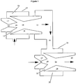
- Figure 1 is a sectional schematic diagram of tandem supersonic ejectors in accordance with the present invention.
- the first supersonic ejector comprises an enclosure 11, which is airtight or substantially airtight that encloses a suction port 12.
- the suction port 12 of the first supersonic ejector 10 may be annular.
- the motive gas enters the nozzle 17 of the first supersonic ejector, is expanded through a constricted throat 13, and is further expanded through the diverging section of the nozzle to a much lower pressure and high supersonic velocity.
- the combined motive gas and the off gas proceed to diffuser 18 of the first supersonic ejector having a larger throat 14 than that of the nozzle 17.
- the cross sectional area of the throat 14 of the diffuser of the first ejector is larger in size than the cross sectional area of the throat 13 of the nozzle 17. Due to the converging and then diverging sections of the cross section area of the channel through the diffuser the speed of the motive gas and entrained off gas decreases.
- the suction port 22 of the second supersonic ejector 20 may be annular.
- the motive gas enters the nozzle 27 of the second supersonic ejector and proceeds to the constricted throat 23, is expanded through the diverging section of the nozzle 27 exits the nozzle at exit 29 and proceeds to diffuser 28 having a larger throat 24 than throat 23 of nozzle 27.
- the cross sectional area of the channel through the second supersonic ejector also increases in size from throat 23 of the nozzle 27 to the throat 24 of the diffuser 28. This increases the velocity of the motive gas as it passes through throat 23 and the diverging section of the nozzle 27and reduces the pressure drawing the exit gas from the first supersonic ejector passing through port 16 into the ejector through suction port 22.
- a motive gas at a higher pressure than the off gas in the case of a pipeline the natural gas within the line and in the case of a chemical plant likely process steam is injected into nozzle 17 of the first supersonic ejector 10.
- the cross section area of the ejector narrows to a throat section 13 of the first supersonic ejector. This increases the velocity of the gas as it passes through the throat and continues to expand through the diverging section of nozzle 17 to exit 19, which creates a lower pressure at the suction inlet 12 of the first supersonic ejector 10.
- the off gas is drawn into and entrained with the motive gas passing through the first supersonic ejector.
- the cross section area of the throat 14 of the diffuser 18 is larger than throat 13 of the nozzle 17.
- the diffuser 18 expands to a discharge 15 into or is fed to the suction port 22 for the second supersonic ejector 20.
- a second motive gas is fed to the nozzle 27 of the second supersonic ejector, which narrows to throat 23.
- the gas velocity increases and the pressure drops drawing the off gas into the nozzle and leaves at exit 29.
- the cross section area of the second supersonic ejector also increases to a throat 24 of the diffuser 28 and further then expands to a discharge port 25.
- the discharge port 25 then feeds a line (not shown) which directs the recompressed off gas to subsequent processing at a higher pressure.
- the nozzles (17 and 27) of the supersonic ejectors are adjustable relative to the diffusers. Typically this is done by having the nozzle threaded and mounted on receiving threads on the enclosure or on a portion of the inlet to the diffuser in a manner not to close the suction port.
- the ejectors should be designed so that the first supersonic ejector is operated at an exit Mach number from 2.4 to 2.6 and the second supersonic ejector is operated at an exit Mach number from 1.6 to 1.8.
- the ratio of the cross section area of the nozzle exit 19 to the nozzle throat 13 is from 2.9 to 3.2, preferably from 3.0 to 3.1.
- the ratio of the cross section area of the nozzle exit 29 to the nozzle throat 23 is from 1.30 to 1.45, preferably from 1.35 to 1.40.
- the ratio of the area of the throat 14 of the diffuser 18 to the throat 13 of the nozzle 17 of the first supersonic ejector may range from about 4.60 to about 4.90, preferably from 4.70 to 4.80.
- the ratio of the area of the throat 24 of the diffuser 28 to the throat 23 of the nozzle 27 of the second supersonic ejector may range from about 1.70 to about 1.90, preferably from 1.80 to 1.90.
- the ratio of the motive gas flow rate to the first supersonic gas ejector to the off gas flow rate is from 32 to 45. (e.g. either g per g or Kg per Kg as this is a unitless ratio).
- the ratio between the motive gas flow rate to the second supersonic gas ejector and the discharge flow from the first supersonic ejector is from 20 to 25.
- Equations (1) and (4) are solved simultaneously along a known geometry-diverging nozzle to delineate the pressure profile along the nozzle as well as all other local flow parameters.
- a proper equation of state such as American Gas Association Report Number 8 equation of state for hydrocarbon gases (AGA-8), must be utilized to account for real gas properties.
- AGA-8 American Gas Association Report Number 8 equation of state for hydrocarbon gases
- the recompressed off gas - natural gas may be fed to a power means such as a gas fired turbine.
- a power means such as a gas fired turbine or it could be fed to a flare gas tower or it could be recycled back to the process.
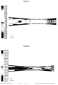
- FIGS. 2 and 3 show an example of CFD results showing the Mach number and stagnation pressure at nozzle exit and through the diffuser. This is an example of an optimized nozzle/diffuser arrangement showing that the nozzle is clear from a standing shock wave, which is good for suction. It is also shown that the shock wave region (which is the region were Mach number drops sharply from supersonic to subsonic - Fig. 2 ) is located at the throat of the diffuser or slightly downstream. This is also preferable for minimum stagnation pressure losses, as is also confirmed by the stagnation pressure contours of Fig. 3 .
- ⁇ m ⁇ 1 + m ⁇ 2 ⁇ 3 m ⁇ 1 ⁇ 1
- ⁇ is the thermodynamic availability (exergy)
- subscript 1,2,3 refer to motive, suction and discharge conditions.
- the above definition was used later in assessing the various nozzle geometry and respective position with respect to the diffuser.
- the supersonic diffuser has an inlet diameter of 4 mm, a throat diameter of 3.5 mm and length of 8 mm, and an exit diameter of 18 mm. Inlet 1 ⁇ 2-angle of the inlet section is 4.7°, while that of the exit section is 5°.
- Several supersonic converging/diverging nozzles were fabricated with different throat diameters and exit/throat area ratios as shown in Table 1. TABLE 1 Various Supersonic Nozzle Tested in the 1 st Stage Ejector Throat (mm) Exit (mm) Area Ratio 3 4.5 2.25 8 7.11 2 2.5 1.56 3 2.25 3.5 3.06 4 4.00 5 6.25 1.6 2.4 2.25 2.8 3.06
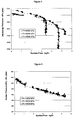
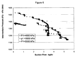
- the data shows that the present optimized configuration is capable of delivering the required discharge pressure (P out ) of 3300 kPa-g with a suction flow of 2-2.5 kg/hr and suction pressure (P 2 ) of 340 kPa-g.
- P out required discharge pressure
- P 2 suction pressure
- the ejectors of the present invention are useful in recovering lower pressure gases and injecting them back into a higher pressure system such as a pipeline or a chemical reactor.
Landscapes
- Engineering & Computer Science (AREA)
- Mechanical Engineering (AREA)
- General Engineering & Computer Science (AREA)
- Environmental & Geological Engineering (AREA)
- Physics & Mathematics (AREA)
- Fluid Mechanics (AREA)
- Chemical & Material Sciences (AREA)
- Combustion & Propulsion (AREA)
- Jet Pumps And Other Pumps (AREA)
- Lasers (AREA)
Claims (15)
- Procédé pour la repressurisation d'un effluent gazeux, ayant une pression comprise entre 68,94 kPa-g (10 psig) et 344,7 kPa-g (50 psig), à une pression comprise entre 2 068,2 kPa-g (300 psig) et 3 447 kPa-g (500 psig), comprenant :l'utilisation d'au moins deux éjecteurs de gaz supersoniques (10, 20) en tandem, dans lequelun éjecteur de gaz supersonique en amont (10) des au moins deux éjecteurs de gaz supersoniques fonctionne à un nombre de Mach de sortie de buse supérieur à un nombre de Mach de sortie de buse d'un éjecteur de gaz supersonique en aval suivant (20) des au moins deux éjecteurs de gaz supersoniques, etun rapport d'une aire de section transversale d'une sortie de buse (19) sur un col de buse (13) de l'éjecteur supersonique amont (10) est de 2,9 à 3,2, et un rapport d'une aire de section transversale d'une sortie de buse (29) sur un col de buse (23) d'au moins l'un des éjecteurs supersoniques en aval suivants (20) est de 1,30 à 1,45.
- Procédé selon la revendication 1, dans lequel l'éjecteur de gaz supersonique en amont (10) des au moins deux éjecteurs de gaz supersoniques (10,20) est actionné à un nombre de Mach de sortie de buse supérieur à 2, et l'éjecteur de gaz supersonique en aval (20) des au moins deux éjecteurs de gaz supersoniques est actionné à un nombre de Mach de sortie de buse inférieur à 2.
- Procédé selon la revendication 2, dans lequel la pression de l'effluent gazeux est comprise entre 172,3 kPa-g (25 psig) et 310,1 kPa-g (45 psig).
- Procédé selon la revendication 3, dans lequel la pression du gaz de repressurisé est comprise entre 2 412,9 kPag (350 psig) et 3 102,3 kPa-g (450 psig).
- Procédé selon la revendication 4, dans lequel une pression d'un gaz sortant de l'éjecteur de gaz supersonique en amont (10) est comprise entre 1 034,1 kPa-g (150 psig) et 1 240,9 kPa-g (180 psig).
- Procédé selon la revendication 5, dans lequel l'effluent gazeux est choisi dans le groupe constitué par des hydrocarbures aromatiques ou aliphatiques en C1-8, qui sont non substitués ou substitués par un ou plusieurs radicaux alkyles en C1-4, des gaz inertes, du CO, du CO2, du N2, du gaz naturel et des mélanges de ceux-ci.
- Procédé selon la revendication 6, dans lequel un rapport d'un débit d'écoulement de gaz moteur vers l'éjecteur de gaz supersonique en amont (10) sur un débit d'écoulement d'effluent gazeux est de 32 à 45.
- Procédé selon la revendication 7, dans lequel un rapport du débit d'écoulement de gaz moteur vers l'éjecteur de gaz supersonique en aval (20) sur un débit d'écoulement de décharge à partir de l'éjecteur de gaz supersonique en amont (10) est de 20 à 25.
- Procédé selon la revendication 8, dans lequel l'éjecteur de gaz supersonique en amont (10) est actionné à un nombre de Mach de sortie de buse de 2,4 à 2,6, et l'éjecteur de gaz supersonique en aval (20) est actionné à un nombre de Mach de sortie de buse de 1,6 à 1.8.
- Procédé selon la revendication 9, dans lequel l'effluent gazeux est un gaz tampon ou d'étanchéité pour un joint à gaz sec, ou un gaz naturel.
- Procédé selon la revendication 10, dans lequel le gaz tampon ou d'étanchéité est introduit dans le joint à gaz sec à une pression comprise entre 5 515,2 kPa-g (800 psig) à 6 894 kPa-g (1 000 psig).
- Procédé selon la revendication 11, dans lequel le débit d'écoulement de l'effluent gazeux à partir du joint à gaz sec est de 1 à 3 kg/heure.
- Procédé selon la revendication 12, dans lequel le gaz tampon ou d'étanchéité est introduit dans l'éjecteur de gaz supersonique en amont (10) à une pression comprise entre 68,94 kPa-g (10 psig) et 344,7-kPa g (50 psig).
- Procédé selon la revendication 13, dans lequel l'effluent gazeux repressurisé est alimenté vers une turbine au gaz naturel ou une chaudière au gaz naturel.
- Procédé selon la revendication 9, dans lequel l'effluent gazeux provient d'une réaction chimique ou d'un bac de purge, ou dans lequel le gaz repressurisé est introduit dans une torche ou dans le réacteur chimique.
Applications Claiming Priority (2)
| Application Number | Priority Date | Filing Date | Title |
|---|---|---|---|
| CA2560814A CA2560814C (fr) | 2006-09-25 | 2006-09-25 | Ejecteurs supersoniques en tandem |
| PCT/CA2007/001476 WO2008037059A1 (fr) | 2006-09-25 | 2007-08-27 | Éjecteurs supersoniques en tandem |
Publications (3)
| Publication Number | Publication Date |
|---|---|
| EP2094971A1 EP2094971A1 (fr) | 2009-09-02 |
| EP2094971A4 EP2094971A4 (fr) | 2012-05-16 |
| EP2094971B1 true EP2094971B1 (fr) | 2016-08-10 |
Family
ID=39229664
Family Applications (1)
| Application Number | Title | Priority Date | Filing Date |
|---|---|---|---|
| EP07800502.2A Not-in-force EP2094971B1 (fr) | 2006-09-25 | 2007-08-27 | Éjecteurs supersoniques en tandem |
Country Status (5)
| Country | Link |
|---|---|
| US (1) | US8100671B2 (fr) |
| EP (1) | EP2094971B1 (fr) |
| CA (1) | CA2560814C (fr) |
| NO (1) | NO20091650L (fr) |
| WO (1) | WO2008037059A1 (fr) |
Families Citing this family (25)
| Publication number | Priority date | Publication date | Assignee | Title |
|---|---|---|---|---|
| AU2009291925B2 (en) * | 2008-09-09 | 2015-11-19 | Dresser-Rand Company | Supersonic ejector package |
| KR20120093060A (ko) | 2009-03-25 | 2012-08-22 | 카이틴, 아이엔씨. | 초음파 냉각 시스템 |
| US8505322B2 (en) * | 2009-03-25 | 2013-08-13 | Pax Scientific, Inc. | Battery cooling |
| US8820114B2 (en) | 2009-03-25 | 2014-09-02 | Pax Scientific, Inc. | Cooling of heat intensive systems |
| US20110048048A1 (en) * | 2009-03-25 | 2011-03-03 | Thomas Gielda | Personal Cooling System |
| US20110048062A1 (en) * | 2009-03-25 | 2011-03-03 | Thomas Gielda | Portable Cooling Unit |
| US20110051549A1 (en) * | 2009-07-25 | 2011-03-03 | Kristian Debus | Nucleation Ring for a Central Insert |
| US8365540B2 (en) * | 2009-09-04 | 2013-02-05 | Pax Scientific, Inc. | System and method for heat transfer |
| GB201002666D0 (en) * | 2010-02-17 | 2010-04-07 | Pursuit Dynamics Plc | Apparatus and method for entraining fluids |
| US8925520B2 (en) * | 2010-03-10 | 2015-01-06 | Ford Global Technologies, Llc | Intake system including vacuum aspirator |
| WO2012097192A2 (fr) * | 2011-01-14 | 2012-07-19 | Caitin, Inc. | Système d'absorption de vapeur |
| US9869190B2 (en) | 2014-05-30 | 2018-01-16 | General Electric Company | Variable-pitch rotor with remote counterweights |
| US10072510B2 (en) | 2014-11-21 | 2018-09-11 | General Electric Company | Variable pitch fan for gas turbine engine and method of assembling the same |
| US10100653B2 (en) | 2015-10-08 | 2018-10-16 | General Electric Company | Variable pitch fan blade retention system |
| US10429067B2 (en) | 2016-11-30 | 2019-10-01 | Saudi Arabian Oil Company | Dynamic multi-legs ejector for use in emergency flare gas recovery system |
| DE102019109195A1 (de) * | 2019-04-08 | 2020-10-08 | Norma Germany Gmbh | Strahlpumpe |
| WO2022271824A1 (fr) * | 2021-06-25 | 2022-12-29 | Cummins Inc. | Configurations de piles à combustible à éjecteur multiple pendant des opérations transitoires |
| US11674435B2 (en) | 2021-06-29 | 2023-06-13 | General Electric Company | Levered counterweight feathering system |
| US11795964B2 (en) | 2021-07-16 | 2023-10-24 | General Electric Company | Levered counterweight feathering system |
| CA3192203A1 (fr) | 2022-03-08 | 2023-09-08 | Rem Technology Inc. | Methode, systeme de commande et systeme d'ejecteur pour faire penetrer un gaz evacue dans une unite |
| US12385604B2 (en) * | 2022-08-31 | 2025-08-12 | Dresser, Llc | Re-couping actuating media used to operate a control valve |
| US12601271B2 (en) | 2022-10-21 | 2026-04-14 | General Electric Company | Variable pitch fan of a gas turbine engine |
| US20240189785A1 (en) * | 2022-11-14 | 2024-06-13 | Dean Lee Millar | Measure to Improve Liquid-Gas Eductor Performance |
| US11835183B1 (en) | 2023-02-01 | 2023-12-05 | Flowserve Management Company | Booster-ejector system for capturing and recycling leakage fluids |
| CN118934759B (zh) * | 2024-08-08 | 2025-09-19 | 武汉安耐捷科技工程有限公司 | 一种大流量真空发生器 |
Citations (1)
| Publication number | Priority date | Publication date | Assignee | Title |
|---|---|---|---|---|
| US5839884A (en) * | 1994-08-18 | 1998-11-24 | Mannesmann Ag | Supersonic jet pump device with two drive nozzles |
Family Cites Families (19)
| Publication number | Priority date | Publication date | Assignee | Title |
|---|---|---|---|---|
| US1806941A (en) * | 1931-05-26 | Matic | ||
| US1449220A (en) * | 1919-05-10 | 1923-03-20 | Elliott Co | Ejector apparatus for exhausting air or other fluids |
| US1777239A (en) * | 1927-12-09 | 1930-09-30 | G & J Weir Ltd | Ejector in series |
| US2555812A (en) * | 1948-02-19 | 1951-06-05 | Ingersoll Rand Co | Thermocompressor |
| US2937140A (en) * | 1956-07-19 | 1960-05-17 | Phillips Petroleum Co | Treatment of petroleum well effluents |
| US3064878A (en) * | 1958-01-03 | 1962-11-20 | Nash Engineering Co | Method and apparatus for high performance evacuation system |
| US3932111A (en) * | 1974-10-29 | 1976-01-13 | Black, Sivalls & Bryson, Inc. | Apparatus for incinerating combustible wastes |
| US4430046A (en) * | 1980-06-18 | 1984-02-07 | Ctp Partners | Method and apparatus for total energy systems |
| US4379679A (en) * | 1980-12-01 | 1983-04-12 | United Technologies Corporation | Supersonic/supersonic fluid ejector |
| US5195587A (en) * | 1992-03-04 | 1993-03-23 | Conoco Inc. | Vapor recovery system |
| US5575894A (en) * | 1995-01-25 | 1996-11-19 | Gas Research Institute | Water and organic constituent separator and stripper system and method |
| US5647221A (en) * | 1995-10-10 | 1997-07-15 | The George Washington University | Pressure exchanging ejector and refrigeration apparatus and method |
| US6315000B1 (en) * | 2000-04-18 | 2001-11-13 | Mark A. Goodyear | Eductor system and method for vapor recovery |
| GB0204139D0 (en) * | 2002-02-21 | 2002-04-10 | Alpha Thames Ltd | Electric motor protection system |
| US6666027B1 (en) * | 2002-07-15 | 2003-12-23 | General Electric Company | Turbine power generation systems and methods using off-gas fuels |
| US7624564B2 (en) * | 2004-07-23 | 2009-12-01 | Power Systems Mfg., Llc | Apparatus and method for providing an off-gas to a combustion system |
| US8113181B2 (en) * | 2005-03-09 | 2012-02-14 | Rem Technology Inc. | Method and apparatus for capturing and controlling fugitive gases |
| US20090320478A1 (en) * | 2006-01-04 | 2009-12-31 | General Electric Company | Reduced boundary layer separation steam jet air ejector assembly and method |
| US8066023B2 (en) * | 2007-04-10 | 2011-11-29 | Black & Veatch Corporation | System and method for collecting and increasing the pressure of seal leak gas |
-
2006
- 2006-09-25 CA CA2560814A patent/CA2560814C/fr active Active
-
2007
- 2007-05-31 US US11/809,342 patent/US8100671B2/en not_active Expired - Fee Related
- 2007-08-27 EP EP07800502.2A patent/EP2094971B1/fr not_active Not-in-force
- 2007-08-27 WO PCT/CA2007/001476 patent/WO2008037059A1/fr not_active Ceased
-
2009
- 2009-04-24 NO NO20091650A patent/NO20091650L/no not_active Application Discontinuation
Patent Citations (1)
| Publication number | Priority date | Publication date | Assignee | Title |
|---|---|---|---|---|
| US5839884A (en) * | 1994-08-18 | 1998-11-24 | Mannesmann Ag | Supersonic jet pump device with two drive nozzles |
Non-Patent Citations (1)
| Title |
|---|
| N C BAINES ET AL: "THE AMERICAN SOCIETY OF MECHANICAL ENGINEERS THE USE OF TANDEM EJECTOR PUMPS IN AN INTERMITTENT BLOWDOWN TUNNEL", ASME 1984 INTERNATIONAL GAS TURBINE CONFERENCE AND EXHIBIT, vol. 5, 4 June 1984 (1984-06-04), pages 1 - 8, XP055204626, ISBN: 978-0-79-187950-4 * |
Also Published As
| Publication number | Publication date |
|---|---|
| EP2094971A1 (fr) | 2009-09-02 |
| CA2560814A1 (fr) | 2008-03-25 |
| EP2094971A4 (fr) | 2012-05-16 |
| NO20091650L (no) | 2009-06-19 |
| WO2008037059A1 (fr) | 2008-04-03 |
| US20080105315A1 (en) | 2008-05-08 |
| US8100671B2 (en) | 2012-01-24 |
| CA2560814C (fr) | 2014-08-26 |
Similar Documents
| Publication | Publication Date | Title |
|---|---|---|
| EP2094971B1 (fr) | Éjecteurs supersoniques en tandem | |
| US6877960B1 (en) | Lobed convergent/divergent supersonic nozzle ejector system | |
| US8672644B2 (en) | Supersonic ejector package | |
| US8066023B2 (en) | System and method for collecting and increasing the pressure of seal leak gas | |
| US8281600B2 (en) | Thimble, sleeve, and method for cooling a combustor assembly | |
| US8696793B2 (en) | Gas liquefaction and separation device utilizing subsonic and supersonic nozzles | |
| US8006961B1 (en) | Apparatus and method for treating process fluid | |
| CN112483479B (zh) | 一种静止式振荡射流引射增压装置 | |
| RU2135840C1 (ru) | Жидкостно-газовый струйный аппарат (варианты) | |
| US9545604B2 (en) | Solids combining system for a solid feedstock | |
| KR101200284B1 (ko) | 충격파 발생기를 이용한 진공 이젝터 성능개선 장치 | |
| US20070025862A1 (en) | Compressible gas ejector with unexpanded motive gas-load gas interface | |
| CN111120422A (zh) | 一种抽真空引射器及发动机抽真空方法 | |
| US6364626B1 (en) | Liquid-gas jet apparatus | |
| Green | Jet pumps and ejectors | |
| Botros et al. | Development of a Supersonic Ejector for Capturing Very Low-Pressure Vent Gases and Re-Injection Into a High-Pressure Gas Stream | |
| RU237199U1 (ru) | Устройство для принудительного удаления воздуха из временных герметизирующих устройств | |
| RU2567413C2 (ru) | Способ ремонта магистрального газопровода и передвижная газоперекачивающая установка для его осуществления | |
| CN115615066B (zh) | 一种碳减排制冷循环方法 | |
| Jansen et al. | Design and investigations of a three dimensionally twisted diffuser for centrifugal compressors | |
| WO2026020011A1 (fr) | Buse insérable pour diriger ou diffuser un écoulement dans un récipient séparateur | |
| CN116550485A (zh) | 一种降尘用终端发泡装置 | |
| RU1800135C (ru) | Способ работы изобарического эжектора | |
| CN202558270U (zh) | 压气送粉机 | |
| Biba et al. | Supersonic Ejectors for Hydrocarbon Emissions Capture |
Legal Events
| Date | Code | Title | Description |
|---|---|---|---|
| PUAI | Public reference made under article 153(3) epc to a published international application that has entered the european phase |
Free format text: ORIGINAL CODE: 0009012 |
|
| 17P | Request for examination filed |
Effective date: 20090427 |
|
| AK | Designated contracting states |
Kind code of ref document: A1 Designated state(s): AT BE BG CH CY CZ DE DK EE ES FI FR GB GR HU IE IS IT LI LT LU LV MC MT NL PL PT RO SE SI SK TR |
|
| DAX | Request for extension of the european patent (deleted) | ||
| A4 | Supplementary search report drawn up and despatched |
Effective date: 20120417 |
|
| RIC1 | Information provided on ipc code assigned before grant |
Ipc: F23G 7/08 20060101ALI20120411BHEP Ipc: F04F 5/46 20060101ALI20120411BHEP Ipc: F04F 5/18 20060101AFI20120411BHEP |
|
| 17Q | First examination report despatched |
Effective date: 20150803 |
|
| GRAP | Despatch of communication of intention to grant a patent |
Free format text: ORIGINAL CODE: EPIDOSNIGR1 |
|
| INTG | Intention to grant announced |
Effective date: 20160331 |
|
| GRAS | Grant fee paid |
Free format text: ORIGINAL CODE: EPIDOSNIGR3 |
|
| GRAA | (expected) grant |
Free format text: ORIGINAL CODE: 0009210 |
|
| AK | Designated contracting states |
Kind code of ref document: B1 Designated state(s): AT BE BG CH CY CZ DE DK EE ES FI FR GB GR HU IE IS IT LI LT LU LV MC MT NL PL PT RO SE SI SK TR |
|
| REG | Reference to a national code |
Ref country code: GB Ref legal event code: FG4D |
|
| REG | Reference to a national code |
Ref country code: CH Ref legal event code: EP Ref country code: AT Ref legal event code: REF Ref document number: 819329 Country of ref document: AT Kind code of ref document: T Effective date: 20160815 |
|
| REG | Reference to a national code |
Ref country code: IE Ref legal event code: FG4D |
|
| REG | Reference to a national code |
Ref country code: DE Ref legal event code: R096 Ref document number: 602007047404 Country of ref document: DE |
|
| REG | Reference to a national code |
Ref country code: LT Ref legal event code: MG4D |
|
| REG | Reference to a national code |
Ref country code: NL Ref legal event code: MP Effective date: 20160810 |
|
| REG | Reference to a national code |
Ref country code: AT Ref legal event code: MK05 Ref document number: 819329 Country of ref document: AT Kind code of ref document: T Effective date: 20160810 |
|
| PG25 | Lapsed in a contracting state [announced via postgrant information from national office to epo] |
Ref country code: FI Free format text: LAPSE BECAUSE OF FAILURE TO SUBMIT A TRANSLATION OF THE DESCRIPTION OR TO PAY THE FEE WITHIN THE PRESCRIBED TIME-LIMIT Effective date: 20160810 Ref country code: IS Free format text: LAPSE BECAUSE OF FAILURE TO SUBMIT A TRANSLATION OF THE DESCRIPTION OR TO PAY THE FEE WITHIN THE PRESCRIBED TIME-LIMIT Effective date: 20161210 Ref country code: IT Free format text: LAPSE BECAUSE OF FAILURE TO SUBMIT A TRANSLATION OF THE DESCRIPTION OR TO PAY THE FEE WITHIN THE PRESCRIBED TIME-LIMIT Effective date: 20160810 Ref country code: NL Free format text: LAPSE BECAUSE OF FAILURE TO SUBMIT A TRANSLATION OF THE DESCRIPTION OR TO PAY THE FEE WITHIN THE PRESCRIBED TIME-LIMIT Effective date: 20160810 Ref country code: LT Free format text: LAPSE BECAUSE OF FAILURE TO SUBMIT A TRANSLATION OF THE DESCRIPTION OR TO PAY THE FEE WITHIN THE PRESCRIBED TIME-LIMIT Effective date: 20160810 |
|
| PG25 | Lapsed in a contracting state [announced via postgrant information from national office to epo] |
Ref country code: PL Free format text: LAPSE BECAUSE OF FAILURE TO SUBMIT A TRANSLATION OF THE DESCRIPTION OR TO PAY THE FEE WITHIN THE PRESCRIBED TIME-LIMIT Effective date: 20160810 Ref country code: SE Free format text: LAPSE BECAUSE OF FAILURE TO SUBMIT A TRANSLATION OF THE DESCRIPTION OR TO PAY THE FEE WITHIN THE PRESCRIBED TIME-LIMIT Effective date: 20160810 Ref country code: GR Free format text: LAPSE BECAUSE OF FAILURE TO SUBMIT A TRANSLATION OF THE DESCRIPTION OR TO PAY THE FEE WITHIN THE PRESCRIBED TIME-LIMIT Effective date: 20161111 Ref country code: BE Free format text: LAPSE BECAUSE OF NON-PAYMENT OF DUE FEES Effective date: 20160831 Ref country code: ES Free format text: LAPSE BECAUSE OF FAILURE TO SUBMIT A TRANSLATION OF THE DESCRIPTION OR TO PAY THE FEE WITHIN THE PRESCRIBED TIME-LIMIT Effective date: 20160810 Ref country code: LV Free format text: LAPSE BECAUSE OF FAILURE TO SUBMIT A TRANSLATION OF THE DESCRIPTION OR TO PAY THE FEE WITHIN THE PRESCRIBED TIME-LIMIT Effective date: 20160810 Ref country code: PT Free format text: LAPSE BECAUSE OF FAILURE TO SUBMIT A TRANSLATION OF THE DESCRIPTION OR TO PAY THE FEE WITHIN THE PRESCRIBED TIME-LIMIT Effective date: 20161212 Ref country code: AT Free format text: LAPSE BECAUSE OF FAILURE TO SUBMIT A TRANSLATION OF THE DESCRIPTION OR TO PAY THE FEE WITHIN THE PRESCRIBED TIME-LIMIT Effective date: 20160810 |
|
| REG | Reference to a national code |
Ref country code: DE Ref legal event code: R119 Ref document number: 602007047404 Country of ref document: DE |
|
| REG | Reference to a national code |
Ref country code: CH Ref legal event code: PL |
|
| PG25 | Lapsed in a contracting state [announced via postgrant information from national office to epo] |
Ref country code: RO Free format text: LAPSE BECAUSE OF FAILURE TO SUBMIT A TRANSLATION OF THE DESCRIPTION OR TO PAY THE FEE WITHIN THE PRESCRIBED TIME-LIMIT Effective date: 20160810 Ref country code: EE Free format text: LAPSE BECAUSE OF FAILURE TO SUBMIT A TRANSLATION OF THE DESCRIPTION OR TO PAY THE FEE WITHIN THE PRESCRIBED TIME-LIMIT Effective date: 20160810 Ref country code: LI Free format text: LAPSE BECAUSE OF NON-PAYMENT OF DUE FEES Effective date: 20160831 Ref country code: CH Free format text: LAPSE BECAUSE OF NON-PAYMENT OF DUE FEES Effective date: 20160831 |
|
| PG25 | Lapsed in a contracting state [announced via postgrant information from national office to epo] |
Ref country code: SK Free format text: LAPSE BECAUSE OF FAILURE TO SUBMIT A TRANSLATION OF THE DESCRIPTION OR TO PAY THE FEE WITHIN THE PRESCRIBED TIME-LIMIT Effective date: 20160810 Ref country code: BG Free format text: LAPSE BECAUSE OF FAILURE TO SUBMIT A TRANSLATION OF THE DESCRIPTION OR TO PAY THE FEE WITHIN THE PRESCRIBED TIME-LIMIT Effective date: 20161110 Ref country code: CZ Free format text: LAPSE BECAUSE OF FAILURE TO SUBMIT A TRANSLATION OF THE DESCRIPTION OR TO PAY THE FEE WITHIN THE PRESCRIBED TIME-LIMIT Effective date: 20160810 Ref country code: DK Free format text: LAPSE BECAUSE OF FAILURE TO SUBMIT A TRANSLATION OF THE DESCRIPTION OR TO PAY THE FEE WITHIN THE PRESCRIBED TIME-LIMIT Effective date: 20160810 Ref country code: BE Free format text: LAPSE BECAUSE OF FAILURE TO SUBMIT A TRANSLATION OF THE DESCRIPTION OR TO PAY THE FEE WITHIN THE PRESCRIBED TIME-LIMIT Effective date: 20160810 |
|
| REG | Reference to a national code |
Ref country code: IE Ref legal event code: MM4A |
|
| PLBE | No opposition filed within time limit |
Free format text: ORIGINAL CODE: 0009261 |
|
| STAA | Information on the status of an ep patent application or granted ep patent |
Free format text: STATUS: NO OPPOSITION FILED WITHIN TIME LIMIT |
|
| PG25 | Lapsed in a contracting state [announced via postgrant information from national office to epo] |
Ref country code: MC Free format text: LAPSE BECAUSE OF FAILURE TO SUBMIT A TRANSLATION OF THE DESCRIPTION OR TO PAY THE FEE WITHIN THE PRESCRIBED TIME-LIMIT Effective date: 20160810 |
|
| REG | Reference to a national code |
Ref country code: FR Ref legal event code: ST Effective date: 20170602 |
|
| 26N | No opposition filed |
Effective date: 20170511 |
|
| GBPC | Gb: european patent ceased through non-payment of renewal fee |
Effective date: 20161110 |
|
| PG25 | Lapsed in a contracting state [announced via postgrant information from national office to epo] |
Ref country code: DE Free format text: LAPSE BECAUSE OF NON-PAYMENT OF DUE FEES Effective date: 20170301 Ref country code: FR Free format text: LAPSE BECAUSE OF NON-PAYMENT OF DUE FEES Effective date: 20161010 Ref country code: IE Free format text: LAPSE BECAUSE OF NON-PAYMENT OF DUE FEES Effective date: 20160827 |
|
| PG25 | Lapsed in a contracting state [announced via postgrant information from national office to epo] |
Ref country code: SI Free format text: LAPSE BECAUSE OF FAILURE TO SUBMIT A TRANSLATION OF THE DESCRIPTION OR TO PAY THE FEE WITHIN THE PRESCRIBED TIME-LIMIT Effective date: 20160810 Ref country code: LU Free format text: LAPSE BECAUSE OF NON-PAYMENT OF DUE FEES Effective date: 20160827 |
|
| PG25 | Lapsed in a contracting state [announced via postgrant information from national office to epo] |
Ref country code: GB Free format text: LAPSE BECAUSE OF NON-PAYMENT OF DUE FEES Effective date: 20161110 |
|
| PG25 | Lapsed in a contracting state [announced via postgrant information from national office to epo] |
Ref country code: CY Free format text: LAPSE BECAUSE OF FAILURE TO SUBMIT A TRANSLATION OF THE DESCRIPTION OR TO PAY THE FEE WITHIN THE PRESCRIBED TIME-LIMIT Effective date: 20160810 Ref country code: HU Free format text: LAPSE BECAUSE OF FAILURE TO SUBMIT A TRANSLATION OF THE DESCRIPTION OR TO PAY THE FEE WITHIN THE PRESCRIBED TIME-LIMIT; INVALID AB INITIO Effective date: 20070827 |
|
| PG25 | Lapsed in a contracting state [announced via postgrant information from national office to epo] |
Ref country code: TR Free format text: LAPSE BECAUSE OF FAILURE TO SUBMIT A TRANSLATION OF THE DESCRIPTION OR TO PAY THE FEE WITHIN THE PRESCRIBED TIME-LIMIT Effective date: 20160810 Ref country code: MT Free format text: LAPSE BECAUSE OF NON-PAYMENT OF DUE FEES Effective date: 20160831 |