EP2095144B1 - Appareil et procédé audio destinés à être utilisés à proximité d'un système d'imagerie par résonance magnétique - Google Patents
Appareil et procédé audio destinés à être utilisés à proximité d'un système d'imagerie par résonance magnétique Download PDFInfo
- Publication number
- EP2095144B1 EP2095144B1 EP07825684.9A EP07825684A EP2095144B1 EP 2095144 B1 EP2095144 B1 EP 2095144B1 EP 07825684 A EP07825684 A EP 07825684A EP 2095144 B1 EP2095144 B1 EP 2095144B1
- Authority
- EP
- European Patent Office
- Prior art keywords
- microphone
- speaker
- signal
- channel
- patient
- Prior art date
- Legal status (The legal status is an assumption and is not a legal conclusion. Google has not performed a legal analysis and makes no representation as to the accuracy of the status listed.)
- Not-in-force
Links
Images




Classifications
-
- G—PHYSICS
- G01—MEASURING; TESTING
- G01R—MEASURING ELECTRIC VARIABLES; MEASURING MAGNETIC VARIABLES
- G01R33/00—Arrangements or instruments for measuring magnetic variables
- G01R33/20—Arrangements or instruments for measuring magnetic variables involving magnetic resonance
- G01R33/28—Details of apparatus provided for in groups G01R33/44 - G01R33/64
- G01R33/283—Intercom or optical viewing arrangements, structurally associated with NMR apparatus
-
- A—HUMAN NECESSITIES
- A61—MEDICAL OR VETERINARY SCIENCE; HYGIENE
- A61F—FILTERS IMPLANTABLE INTO BLOOD VESSELS; PROSTHESES; DEVICES PROVIDING PATENCY TO, OR PREVENTING COLLAPSING OF, TUBULAR STRUCTURES OF THE BODY, e.g. STENTS; ORTHOPAEDIC, NURSING OR CONTRACEPTIVE DEVICES; FOMENTATION; TREATMENT OR PROTECTION OF EYES OR EARS; BANDAGES, DRESSINGS OR ABSORBENT PADS; FIRST-AID KITS
- A61F11/00—Methods or devices for treatment of the ears or hearing sense; Non-electric hearing aids; Methods or devices for enabling ear patients to achieve auditory perception through physiological senses other than hearing sense; Protective devices for the ears, carried on the body or in the hand
- A61F11/06—Protective devices for the ears
- A61F11/14—Protective devices for the ears external, e.g. earcaps or earmuffs
- A61F11/145—Protective devices for the ears external, e.g. earcaps or earmuffs electric, e.g. for active noise reduction
-
- G—PHYSICS
- G10—MUSICAL INSTRUMENTS; ACOUSTICS
- G10K—SOUND-PRODUCING DEVICES; METHODS OR DEVICES FOR PROTECTING AGAINST, OR FOR DAMPING, NOISE OR OTHER ACOUSTIC WAVES IN GENERAL; ACOUSTICS NOT OTHERWISE PROVIDED FOR
- G10K11/00—Methods or devices for transmitting, conducting or directing sound in general; Methods or devices for protecting against, or for damping, noise or other acoustic waves in general
- G10K11/16—Methods or devices for protecting against, or for damping, noise or other acoustic waves in general
- G10K11/175—Methods or devices for protecting against, or for damping, noise or other acoustic waves in general using interference effects; Masking sound
- G10K11/178—Methods or devices for protecting against, or for damping, noise or other acoustic waves in general using interference effects; Masking sound by electro-acoustically regenerating the original acoustic waves in anti-phase
-
- G—PHYSICS
- G10—MUSICAL INSTRUMENTS; ACOUSTICS
- G10K—SOUND-PRODUCING DEVICES; METHODS OR DEVICES FOR PROTECTING AGAINST, OR FOR DAMPING, NOISE OR OTHER ACOUSTIC WAVES IN GENERAL; ACOUSTICS NOT OTHERWISE PROVIDED FOR
- G10K11/00—Methods or devices for transmitting, conducting or directing sound in general; Methods or devices for protecting against, or for damping, noise or other acoustic waves in general
- G10K11/16—Methods or devices for protecting against, or for damping, noise or other acoustic waves in general
- G10K11/175—Methods or devices for protecting against, or for damping, noise or other acoustic waves in general using interference effects; Masking sound
- G10K11/178—Methods or devices for protecting against, or for damping, noise or other acoustic waves in general using interference effects; Masking sound by electro-acoustically regenerating the original acoustic waves in anti-phase
- G10K11/1785—Methods, e.g. algorithms; Devices
- G10K11/17857—Geometric disposition, e.g. placement of microphones
-
- G—PHYSICS
- G10—MUSICAL INSTRUMENTS; ACOUSTICS
- G10K—SOUND-PRODUCING DEVICES; METHODS OR DEVICES FOR PROTECTING AGAINST, OR FOR DAMPING, NOISE OR OTHER ACOUSTIC WAVES IN GENERAL; ACOUSTICS NOT OTHERWISE PROVIDED FOR
- G10K11/00—Methods or devices for transmitting, conducting or directing sound in general; Methods or devices for protecting against, or for damping, noise or other acoustic waves in general
- G10K11/16—Methods or devices for protecting against, or for damping, noise or other acoustic waves in general
- G10K11/175—Methods or devices for protecting against, or for damping, noise or other acoustic waves in general using interference effects; Masking sound
- G10K11/178—Methods or devices for protecting against, or for damping, noise or other acoustic waves in general using interference effects; Masking sound by electro-acoustically regenerating the original acoustic waves in anti-phase
- G10K11/1787—General system configurations
- G10K11/17879—General system configurations using both a reference signal and an error signal
- G10K11/17881—General system configurations using both a reference signal and an error signal the reference signal being an acoustic signal, e.g. recorded with a microphone
-
- G—PHYSICS
- G10—MUSICAL INSTRUMENTS; ACOUSTICS
- G10K—SOUND-PRODUCING DEVICES; METHODS OR DEVICES FOR PROTECTING AGAINST, OR FOR DAMPING, NOISE OR OTHER ACOUSTIC WAVES IN GENERAL; ACOUSTICS NOT OTHERWISE PROVIDED FOR
- G10K11/00—Methods or devices for transmitting, conducting or directing sound in general; Methods or devices for protecting against, or for damping, noise or other acoustic waves in general
- G10K11/16—Methods or devices for protecting against, or for damping, noise or other acoustic waves in general
- G10K11/175—Methods or devices for protecting against, or for damping, noise or other acoustic waves in general using interference effects; Masking sound
- G10K11/178—Methods or devices for protecting against, or for damping, noise or other acoustic waves in general using interference effects; Masking sound by electro-acoustically regenerating the original acoustic waves in anti-phase
- G10K11/1787—General system configurations
- G10K11/17885—General system configurations additionally using a desired external signal, e.g. pass-through audio such as music or speech
-
- G—PHYSICS
- G10—MUSICAL INSTRUMENTS; ACOUSTICS
- G10K—SOUND-PRODUCING DEVICES; METHODS OR DEVICES FOR PROTECTING AGAINST, OR FOR DAMPING, NOISE OR OTHER ACOUSTIC WAVES IN GENERAL; ACOUSTICS NOT OTHERWISE PROVIDED FOR
- G10K2210/00—Details of active noise control [ANC] covered by G10K11/178 but not provided for in any of its subgroups
- G10K2210/10—Applications
- G10K2210/116—Medical; Dental
- G10K2210/1161—NMR or MRI
Definitions
- the present invention relates to a sound system for use within the fields associated with magnetic resonance equipment, a noise cancellation system for use within the fields of magnetic resonance equipment and a method of performing error correction of auditory signals presented to a patient within the fields of magnetic resonance equipment.
- the present invention relates to devices that are used in conjunction with Magnetic Resonance Imaging (“MRI”) equipment to provide stimuli or entertainment for a patient and to facilitate communication with a patient during an MRI diagnostic treatment or imaging process.
- MRI Magnetic Resonance Imaging
- MRI has become a preferred technology for generation of high quality images of different tissue types within the human body.
- Headphone devices to provide auditory stimulation or entertainment for the patient have been developed and improved for use with MRI equipment.
- the signals that are to be reproduced by the headphones may originate as music or similar entertainment content, communications from the MRI operator to the patient, or patient auditory stimuli used in functional MRI ("fMRI”) and other brain function imaging.
- fMRI functional MRI
- the headphone devices must be able to operate within the MRI environment.
- the MRI environment typically produces intense magnetic fields and further relies on measurement of small radio-frequency signals created by the response of human tissue to stimulation by radio-frequency signals and other magnetic fields.
- the MRI environment is also confined by the dimensions of the MRI equipment. More specifically, most MRI equipment includes a bore into which the patient is moved during the imaging operation.
- Devices operable to sense sound made by the patient are also implemented in the MRI environment. These devices are generally adapted to allow the patient to communicate with the operator of the MRI equipment and provide a way for the operator to confirm that the patient is relaxed and comfortable. Devices used to receive the sound from the patient must also be compatible with the MRI environment.
- the MRI equipment is prone to generating significant amounts of noise during operation. This noise may be created in part by the rapid changes in the current that cause vibration such that knocking can be heard by the patient.
- the noise generated by MRI equipment is typically loud and is generated across a broad frequency spectrum. Additionally, the noise generated varies in intensity during operation of the MRI equipment. The presence of this noise presents the possibility of injury to the patient's hearing, which has been avoided through use of headphones and/or earplugs.
- US-A-2005/0197565 discloses an audio communication apparatus for an MRI apparatus which performs unidirectional or bidirectional audio communication between a subject in a gantry provided in an examination room and an operator in a control room.
- An acoustic transducer for transmission and/or reception provided on the subject side is formed by a bone conduction microphone and/or speaker.
- the bone conduction microphone/speaker transmits a sound to or from the subject by contacting the subject directly or via a protection member, without relying on air as a transmission medium.
- the apparatus carries out audio transmission without being affected by noise, even in a high-noise environment.
- EP-A-0655730 discloses a communication system for use with a magnetic resonance system.
- the communication system comprises means for generating a reference signal which is dependent on the gradient noise and a microphone which is arranged in a region close to the MRI apparatus so as to pick up a mixture of sound information and gradient noise.
- the communication system also comprises a noise suppression device, comprising a filter device for converting the reference signal into a signal which corresponds substantially to the gradient noise at the area of the microphone, and a summing device for adding the output signal of the filter device to the output signal of the microphone in phase opposition, the output of the summing device being connected to one or more further sound reproduction devices. Between the microphone and the summing device are inserted signal delay means which delay the microphone signal for a predetermined period of time.
- the sound reproduction device is provided with means for attenuating sound which does not originate from the sound reproduction device.
- a sound system for use within the fields associated with magnetic resonance equipment comprising:
- a noise cancellation system for use within the fields associated with magnetic resonance equipment, comprising:
- a method of performing error correction of auditory signals presented to a patient located within the fields associated with MRI equipment comprising:
- the following detailed description outlines an MRI-compatible audio system for reproducing and recording sound within the magnetic and RF fields generated by MRI equipment using an earphone device.
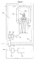
- the MRI equipment is typically installed in at least two rooms.
- the magnet room 101 houses the magnet portion of the MRI equipment 103 along with the RF head coil 105 when necessary and the patient 106.
- the magnet room 101 is typically surrounded by a Faraday cage 116 that effectively insulates the interior of the magnet room from electromagnetic fields and signals from the outside environment.
- the control room 102 houses at least a portion of the control electronics (not shown) and provides means for the operator to observe the patient while supervising the procedure.
- the control electronics within the control room include user interfaces (not shown) to facilitate control of the procedure.
- FIG. 1 includes the earphones 104 that are worn by the patient 106 during the operation of the MRI equipment.
- the earphones 104 may be positioned inside the bore and include an electrical connection through shielded cable 107 to a housing 110 that is comprised of a Faraday cage to effectively isolate the contents of the housing from the magnet room 101.
- a housing 110 that is comprised of a Faraday cage to effectively isolate the contents of the housing from the magnet room 101.
- an audio system control unit 108 Within the housing 110, there is an audio system control unit 108 that receives an electrical signal from the fiber optic transceiver unit 109, which converts a light signal from the control room 102 into an electrical signal.
- the fiber optic transceiver unit 109 is connected to another fiber optic transceiver unit 114 through a fiber optic cable 111 that is passed through a wave guide 112.
- the dimensions of the wave guide 112 are calculated so that only non-disturbing frequencies will enter the magnet room 101.
- the wave guide 112 is typically a tube mounted on the Faraday cage 116 that surrounds the magnet room 101.
- the fiber optic transceiver 114 is electrically connected to the audio input/output source 115 for the system.
- an earplug 104 is formed by a housing 201-202.
- the earplug housing optimally is shaped for placement adjacent to the head of the patient to have minimal obstruction of the RF head coil, if one is used.
- Within the earplug housing there is a speaker element 203 that reproduces sound for the patient.
- the speaker element 203 may be formed from a membrane 208 and two stators 209.
- the stators 209 are reference points for the moveable membrane 208.
- the audio signal is transformed into two high-voltage signals within the audio system control unit 108. These signals will typically have identical power and phase and are connected to each stator 209 which results in the generation of an electrostatic field. This field will work either with or against the membrane 208 to generate sound.
- Other speaker elements that reduce the use of magnetic materials and that are sufficiently shielded may be substituted for the electrostatic speaker element 203.
- the housing 201, 202 also contains at least one microphone 205.
- the microphone 205 may be placed inboard of the speaker 203 toward the patient 106 in the housing part 201, 202, thus ensuring best performance in picking up patient communication.
- Microphone 205 records the patient's voice and otherwise provides a signal for use in error correction of the active noise cancellation process discussed with reference to FIGs. 5 and 6 .
- the microphone 205 is positioned within the housing 201, 202 such that it is within a channel 207 that is defined when the earplug 104 is put in contact with the patient's ear.
- This channel 207 is formed whether the housing 201, 202 is formed to be inserted into the ear canal or is outside of the ear canal but is otherwise in contact with the ear of the patient.
- This channel 207 is any space that is defined by the contours of the patient's ear, the material implemented for noise attenuation 206 and the components of the earplug such as the speaker element 203 and microphone 205.
- a second microphone 204 may also be implemented to record background noise.
- the second microphone 204 may be placed in the housing 201, 202 facing outwards. This is done so it can pick up the environmental noise related to the surrounding sound from the MRI equipment with best performance, and with minimal disturbance from the speaker element 203.
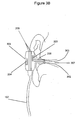
- This microphone 204 may simply be positioned within the housing 201, 202 without any aperture to the environment, or may be implemented with a dedicated aperture 303 (see FIGs. 3A and 3B ) to more directly receive noise generated by the MRI equipment.
- the microphones 204, 205 that can be in this environment include micro-machined silicon (“MEMS”) microphones.
- MEMS microphones are made of poly-silicon and manufactured using semiconductor manufacturing processes that result in a robust microphone that yields a high degree of repeatability and stable acoustic performance.
- Other microphones that reduce the use of magnetic materials and that are sufficiently shielded may also be used.
- FIG. 2 shows replaceable material 206 that is shaped to contact the patient's ear.
- the replaceable material 206 may be formed from foam with known acoustic properties or from other materials, including soft plastic that can seal within the patient's ear and provide noise attenuation.
- the material 206 may be shaped such that it defines a channel 207 when put in contact with the patient's ear within which environmental noise is effectively attenuated.
- Channel 207 may be a single path to the patient's ear with equal access by the speaker element 203 and the microphone 205 as shown in FIG. 2 .
- FIGs. 3A and 3B show an embodiment wherein the channel 207 is formed of two tubes, one tube 302 being coupled to the speaker element and the other tube being coupled to the microphone 205. These tubes may be kept separate as long as possible to achieve minimal disturbance between the auditory stimulus presented by the speaker 203 and the patient's communication picked up by the microphone 205.
- active noise cancellation and error correction constitutes a portion of the audio system control unit 108.
- audio cancellation electronics 402, 403 and an amplifier 401 that amplifies the electrical signal.
- the audio system control unit may produce if necessary the positive and negative high voltage delivered to the speaker element 203 described above.
- the signal enters the speaker element 203 through a shielded cable 107, which may be split into two shielded cables, one for the left and one for the right.
- Active noise cancellation is accomplished by adding filtered and inverted sound from the microphone 204 to the auditory stimuli presented to the patient.
- the sound from the microphone 204 can be filtered to remove high frequency portions of the signal.
- the signal recorded by the microphone 204 represents the noise generated by the MRI equipment. Thus the surrounding sound can effectively be taken out of the auditory signal presented to the patient.
- the sound from the inner microphone 205 may be used as a feedback to the noise cancellation unit 402.
- An error correction for this active noise cancellation is performed by using the signal from the microphone 205 to correct for the mismatch between the noise picked up by the outer microphone 204 and the noise recorded inside the channel 207 formed by contact with the ear of the patient. Because of the distance between the two microphones and their positioning, the sound from the microphone 205 is time-delayed and filtered before it is compared with the microphone 204 for error correction.
- the noise processing component 403 also is operative on the signal that is recorded by the microphone 205 that represents the voice of the patient 106. Before the signal from the microphone 205 is sent to the optic transceiver unit 109 it is cleared of the auditory stimuli presented to the patient coming from the auditory input output source 115. Cancellation is achieved by subtracting the auditory stimuli from the signal from microphone 205 before it is sent to the optic transceiver 109. By this, active noise cancellation of the signal representing the patient's voice is achieved and a clearer representation of the patient's communication is accomplished.
- the auditory stimulation that is to be provided to the patient is processed consistent with the operation of the audio control unit 108.
- the auditory stimuli is first input 501 through the fiber optic transceiver 109.
- the recorded signal from the microphone 204 located outside of the noise attenuation material 206 is provided 502.
- the signal from the microphone 204 is then subtracted from the stimuli 501 such that the signal will include active noise cancellation.
- the resulting signal is then evaluated 504 to determine whether outside noise is still present. This evaluation may be accomplished by comparing the sound output to the patient within the channel 207 which is recorded by microphone 205 to the signal that is desired to be reproduced.
- the noise signal may be amplified to achieve an improved result. As the signal is determined to have achieved the desired amount of noise reduction, the signal resulting from the subtraction 503 is presented to the patient 505.
- the recorded sound that includes the patient's voice is processed to remove an effective amount of the auditory stimuli that is presented to the patient.
- the recorded signal has the benefit of being recorded in the channel 207 that provides noise attenuation and noise cancellation through the process described in FIG. 5 . Additionally, this processing will evaluate whether auditory stimulation was present 602. If so, the process will subtract the auditory stimuli signal from the recorded signal 603. The resulting signal that contains the voice of the patient can be forwarded to MRI equipment operator 604 with benefits of having removed undesired portions of the signal.
Landscapes
- Physics & Mathematics (AREA)
- Engineering & Computer Science (AREA)
- Acoustics & Sound (AREA)
- Multimedia (AREA)
- Health & Medical Sciences (AREA)
- General Health & Medical Sciences (AREA)
- Audiology, Speech & Language Pathology (AREA)
- Condensed Matter Physics & Semiconductors (AREA)
- General Physics & Mathematics (AREA)
- Life Sciences & Earth Sciences (AREA)
- Biophysics (AREA)
- Otolaryngology (AREA)
- Psychology (AREA)
- Biomedical Technology (AREA)
- Heart & Thoracic Surgery (AREA)
- Vascular Medicine (AREA)
- Animal Behavior & Ethology (AREA)
- Public Health (AREA)
- Veterinary Medicine (AREA)
- Magnetic Resonance Imaging Apparatus (AREA)
Claims (9)
- Système sonore destiné à être utilisé dans les champs associés à un équipement à résonance magnétique, comprenant :un logement rigide (201, 202) ;un microphone (205) pour détecter un son émis par un patient ;un haut-parleur (203) ; etun circuit de commande audio (108), caractérisé par :un matériau pliable moulé (206) façonné de telle sorte qu'un canal (207) soit formé avec l'oreille humaine du patient lorsque ledit matériau est placé en contact avec l'oreille humaine, le canal (207) étant un espace défini par des contours de l'oreille humaine, le matériau pliable moulé (206) et le logement rigide (201, 202) ;dans lequel le microphone (205) est positionné à l'intérieur du canal (207) et le haut-parleur (203) est positionné à l'intérieur du canal (207), etdans lequel le circuit de commande (108) est configuré pour recevoir, en utilisation, un signal en provenance du microphone (205) et traiter ce signal en soustrayant un signal utilisé pour faire fonctionner le haut-parleur (203) de sorte que le son du haut-parleur (203) soit partiellement supprimé.
- Système sonore selon la revendication 1, comprenant en outre :un deuxième microphone (204) positionné à l'extérieur du canal (207).
- Système sonore selon la revendication 2, comprenant en outre :un deuxième circuit de commande audio (108) relié électriquement au dit deuxième microphone (204) et au dit haut-parleur (203) utilisable pour soustraire un signal reçu en provenance dudit deuxième microphone (204) à un signal d'entrée pour ledit haut-parleur (203) afin d'engendrer un signal d'entrée modifié à destination dudit haut-parleur (203) qui réduit le son à l'extérieur dudit canal (207) présenté à l'oreille humaine.
- Système sonore selon la revendication 3, comprenant en outre :un troisième circuit de commande audio (108) relié électriquement au dit microphone (205) positionné à l'intérieur du canal (207), au signal d'entrée pour ledit haut-parleur (203) et au deuxième microphone (204) pour comparer le signal reçu en provenance dudit deuxième microphone (204) au signal en provenance dudit microphone (205) positionné à l'intérieur du canal pour déterminer si le bruit présenté à l'oreille humaine est sensiblement réduit.
- Système sonore selon la revendication 4, dans lequel ledit matériau pliable moulé est formé pour fournir un premier tube (302) associé au dit haut-parleur (203) et un deuxième tube (301) associé au dit microphone (205) à l'intérieur du canal.
- Système d'annulation de bruit destiné à être utilisé dans les champs associés à un équipement à résonance magnétique, comprenant :un premier microphone (204) pour détecter un bruit environnemental ;un haut-parleur (203) ; etune unité de commande (108) pour traiter des signaux acoustiques entre un patient et un opérateur ;caractérisé par :un atténuateur (206) pour fournir un degré d'isolation acoustique qui est formé pour créer un canal (207) avec l'oreille d'un patient, dans lequel le premier microphone (204) est positionné à l'extérieur dudit canal (207) et le haut-parleur (203) est positionné à l'intérieur dudit canal (207) ; etun deuxième microphone (205) positionné à l'intérieur dudit canal (207) pour détecter un son émis par le patient,dans lequel l'unité de commande (108) est configurée pour recevoir, en utilisation, un signal destiné à être présenté au patient par l'intermédiaire du haut-parleur et pour traiter ce signal en fonction des signaux reçus en provenance du premier microphone (204) et du deuxième microphone (205) afin de produire un signal modifié à destination du haut-parleur (203) dans lequel le bruit environnemental est réduit.
- Système selon la revendication 6, dans lequel l'unité de commande (108) est agencée pour traiter un son enregistré comprenant la voix du patient en supprimant une quantité efficace de stimuli auditifs présentés au patient, en ce qu'elle est configurée pour soustraire le signal de haut-parleur modifié à un signal en provenance du microphone (205) positionné à l'intérieur dudit atténuateur pour une sortie à destination de l'opérateur.
- Système selon la revendication 6, dans lequel ledit atténuateur (206) est formé pour fournir un premier tube (302) associé au dit haut-parleur (303) et un deuxième tube (301) associé au dit deuxième microphone (205) à l'intérieur dudit atténuateur.
- Procédé d'exécution d'une correction d'erreur de signaux auditifs présentés à un patient situé dans les champs associés à un équipement d'imagerie à résonance magnétique, comprenant :la réception d'un signal de sortie destiné à être présenté au patient par l'intermédiaire d'un haut-parleur (203) positionné dans un canal (207) formé avec une oreille humaine lorsqu'un matériau d'atténuation de bruit (206) d'un système sonore est placé en contact avec l'oreille humaine ;la création d'un premier signal d'entrée en détectant un son émis par l'équipement d'imagerie à résonance magnétique avec un premier microphone (204) positionné à l'extérieur du canal ;la combinaison du premier signal d'entrée au signal de sortie de sorte que le signal de sortie annule sensiblement le son émis par l'équipement d'imagerie à résonance magnétique ;la création d'un deuxième signal d'entrée en détectant le son émis par le haut-parleur (203) avec un deuxième microphone (205) positionné dans le canal (207) ; etla comparaison du deuxième signal d'entrée au premier signal d'entrée pour ajuster la combinaison afin d'annuler davantage le son émis par l'équipement d'imagerie à résonance magnétique.
Priority Applications (1)
| Application Number | Priority Date | Filing Date | Title |
|---|---|---|---|
| PL07825684T PL2095144T3 (pl) | 2006-11-22 | 2007-11-09 | Aparat audio przeznaczony do użytku wraz z systemami obrazowania rezonansem magnetycznym |
Applications Claiming Priority (2)
| Application Number | Priority Date | Filing Date | Title |
|---|---|---|---|
| US11/562,752 US8085942B2 (en) | 2006-11-22 | 2006-11-22 | Audio apparatus and method for use in proximity to a magnetic resonance imaging system |
| PCT/IB2007/003521 WO2008062275A1 (fr) | 2006-11-22 | 2007-11-09 | Appareil et procédé audio destinés à être utilisés à proximité d'un système d'imagerie par résonance magnétique |
Publications (2)
| Publication Number | Publication Date |
|---|---|
| EP2095144A1 EP2095144A1 (fr) | 2009-09-02 |
| EP2095144B1 true EP2095144B1 (fr) | 2014-03-19 |
Family
ID=39190299
Family Applications (1)
| Application Number | Title | Priority Date | Filing Date |
|---|---|---|---|
| EP07825684.9A Not-in-force EP2095144B1 (fr) | 2006-11-22 | 2007-11-09 | Appareil et procédé audio destinés à être utilisés à proximité d'un système d'imagerie par résonance magnétique |
Country Status (6)
| Country | Link |
|---|---|
| US (1) | US8085942B2 (fr) |
| EP (1) | EP2095144B1 (fr) |
| CN (1) | CN101535829B (fr) |
| CA (1) | CA2669925A1 (fr) |
| PL (1) | PL2095144T3 (fr) |
| WO (1) | WO2008062275A1 (fr) |
Cited By (2)
| Publication number | Priority date | Publication date | Assignee | Title |
|---|---|---|---|---|
| DE102014214265A1 (de) * | 2014-07-22 | 2016-01-28 | Siemens Aktiengesellschaft | Verfahren zu einem Einstellen eines Lautstärkenwerts einer Kommunikationseinheit sowie eine Kommunikationseinheit |
| EP3315985A1 (fr) * | 2016-10-26 | 2018-05-02 | Siemens Healthcare GmbH | Unité audio mr |
Families Citing this family (29)
| Publication number | Priority date | Publication date | Assignee | Title |
|---|---|---|---|---|
| WO2010018534A1 (fr) * | 2008-08-14 | 2010-02-18 | Koninklijke Philips Electronics N.V. | Masquage de bruit de bobines de gradient pour un dispositif irm |
| US8325951B2 (en) * | 2009-01-20 | 2012-12-04 | General Mems Corporation | Miniature MEMS condenser microphone packages and fabrication method thereof |
| US8363861B2 (en) * | 2009-03-20 | 2013-01-29 | Brian Hughes | Entertainment system for use during the operation of a magnetic resonance imaging device |
| US8942389B2 (en) * | 2011-08-10 | 2015-01-27 | Robert Bosch Gmbh | Trim method for CMOS-MEMS microphones |
| JP5823850B2 (ja) | 2011-12-21 | 2015-11-25 | ジーイー・メディカル・システムズ・グローバル・テクノロジー・カンパニー・エルエルシー | 通信連絡システムおよび磁気共鳴装置 |
| KR101499831B1 (ko) * | 2012-09-25 | 2015-03-18 | 삼성전자 주식회사 | 자기공명영상장치 및 그 제어방법 |
| US9660336B2 (en) * | 2013-02-07 | 2017-05-23 | Kevan ANDERSON | Systems, devices and methods for transmitting electrical signals through a faraday cage |
| WO2014134424A2 (fr) * | 2013-02-28 | 2014-09-04 | The Johns Hopkins University | Câblage de système de déclenchement de résonance magnétique pour imagerie dynamique |
| KR20140125969A (ko) | 2013-04-19 | 2014-10-30 | 삼성전자주식회사 | 소음 제거를 위한 헤드셋 |
| CN104347063B (zh) * | 2013-07-31 | 2019-12-17 | Ge医疗系统环球技术有限公司 | 计算机x射线断层成像系统上消除噪声的方法和装置 |
| CN104519447B (zh) | 2013-10-08 | 2018-12-14 | 三星电子株式会社 | 降噪设备和方法以及具有无磁性扬声器的音频播放设备 |
| GB2519976A (en) * | 2013-11-03 | 2015-05-13 | Carine Henriette Wood | Improvements in and relating to noise cancelling devices |
| CN103856835B (zh) * | 2014-01-29 | 2017-06-13 | 包头市稀宝博为医疗系统有限公司 | 一种用于mri系统的无线多功能呼讲控制台 |
| CN104605854A (zh) * | 2015-02-06 | 2015-05-13 | 李世俊 | 一种32通道儿童专用核磁共振视觉-听觉刺激线圈系统 |
| US10091574B2 (en) | 2015-11-25 | 2018-10-02 | Neocoil, Llc | Method and apparatus for delivering audio signals and providing hearing protection during medical imaging |
| CN105852803A (zh) * | 2016-03-18 | 2016-08-17 | 夏士桀 | 一种用于磁共振视觉传输的高保真音频输出电路 |
| CN107334577B (zh) * | 2016-10-31 | 2023-07-04 | 赵宁 | 用于核磁共振检查的消音耳机 |
| AU2017365735A1 (en) | 2016-11-28 | 2019-07-11 | Innovere Medical Inc. | Systems, methods and devices for communication in noisy environments |
| CN107320241B (zh) * | 2017-07-25 | 2019-01-15 | 青岛大学附属医院 | 一种用于磁共振扫描的头戴式降噪耳罩 |
| CN107822635A (zh) * | 2017-11-27 | 2018-03-23 | 佛山市恒爱网络科技有限公司 | 磁共振扫描刺激机 |
| US11012788B2 (en) * | 2018-03-27 | 2021-05-18 | Sony Corporation | Loudspeaker system |
| CN111654303B (zh) * | 2019-02-18 | 2022-02-08 | 诸爱道 | 一种核磁共振通话设备 |
| JP2020163098A (ja) * | 2019-03-26 | 2020-10-08 | 日東電工株式会社 | 耳栓、集音装置、及び、音量測定システム |
| WO2020196017A1 (fr) * | 2019-03-26 | 2020-10-01 | 日東電工株式会社 | Bouchon d'oreille, dispositif de collecte de sons et système de mesure de volume sonore |
| CN111785240B (zh) * | 2020-08-03 | 2021-04-09 | 上海全景医学影像诊断中心有限公司 | 用于pet-mr工作噪音的反相干涉滤波主动波防护设备 |
| JP7091412B2 (ja) * | 2020-09-25 | 2022-06-27 | ジーイー・プレシジョン・ヘルスケア・エルエルシー | 医用装置およびプログラム |
| CN113782224A (zh) * | 2021-09-13 | 2021-12-10 | 上海联影医疗科技股份有限公司 | 交互装置、核磁共振系统和控制方法 |
| NO20211478A1 (en) * | 2021-12-08 | 2023-04-11 | Nordicneurolab As | Audio System for MRI |
| EP4420601A1 (fr) | 2023-02-23 | 2024-08-28 | Koninklijke Philips N.V. | Sélection guidée par résonance magnétique de commandes de commande de stimulus sensoriel pour acouphène |
Family Cites Families (20)
| Publication number | Priority date | Publication date | Assignee | Title |
|---|---|---|---|---|
| US4696030A (en) * | 1985-12-16 | 1987-09-22 | Elscint Ltd. | Patient operator intercom arrangements for magnetic resonance imaging systems |
| US5432544A (en) * | 1991-02-11 | 1995-07-11 | Susana Ziarati | Magnet room display of MRI and ultrasound images |
| US5412419A (en) * | 1991-02-11 | 1995-05-02 | Susana Ziarati | Magnetic resonance imaging compatible audio and video system |
| JP3114074B2 (ja) * | 1991-06-21 | 2000-12-04 | 株式会社日立製作所 | 医療用診断装置 |
| GB2265790A (en) | 1992-04-02 | 1993-10-06 | Polural Limited | Earphone apparatus with active noise reduction |
| US5251263A (en) * | 1992-05-22 | 1993-10-05 | Andrea Electronics Corporation | Adaptive noise cancellation and speech enhancement system and apparatus therefor |
| WO1994000089A1 (fr) * | 1992-06-19 | 1994-01-06 | Joseph Sylvester Chang | Protection antibruit pour les oreilles |
| US5339813A (en) * | 1993-08-06 | 1994-08-23 | The Mcw Research Foundation, Inc. | Patient video system for medical imaging equipment |
| GB9319498D0 (en) | 1993-09-21 | 1993-11-03 | Marconi Gec Ltd | Magentic resonance apparatus |
| BE1007806A3 (nl) * | 1993-11-30 | 1995-10-24 | Philips Electronics Nv | Magnetisch resonantie apparaat bevattende een communicatiesysteem. |
| US5877732A (en) * | 1994-04-13 | 1999-03-02 | Resonance Technology Co. | Three-dimensional high resolution MRI video and audio system and method |
| US5861865A (en) * | 1995-08-14 | 1999-01-19 | General Electric Company | Audio/visual entertainment system for use with a magnetic resonance imaging device with adjustable video signal |
| US6567524B1 (en) * | 2000-09-01 | 2003-05-20 | Nacre As | Noise protection verification device |
| US7039195B1 (en) * | 2000-09-01 | 2006-05-02 | Nacre As | Ear terminal |
| DE10112305B4 (de) * | 2001-03-14 | 2004-01-08 | Siemens Ag | Gehörschutz und Verfahren zum Betrieb einer geräuschemittierenden Einrichtung |
| DE10151033B4 (de) * | 2001-10-16 | 2012-11-29 | Siemens Ag | Magnetresonanzgerät mit einem ersten und wenigstens drei zweiten Mikrofonen |
| JP2005245580A (ja) * | 2004-03-02 | 2005-09-15 | Azden Corp | Mri装置における音声通信装置 |
| DE102004059678B3 (de) * | 2004-12-10 | 2006-06-01 | Siemens Ag | Gehörschutz zur Verwendung in Magnetresonanzanlagen |
| US7571006B2 (en) * | 2005-07-15 | 2009-08-04 | Brian Gordon | Wearable alarm system for a prosthetic hearing implant |
| US7801319B2 (en) * | 2006-05-30 | 2010-09-21 | Sonitus Medical, Inc. | Methods and apparatus for processing audio signals |
-
2006
- 2006-11-22 US US11/562,752 patent/US8085942B2/en not_active Expired - Fee Related
-
2007
- 2007-11-09 CN CN200780042820.5A patent/CN101535829B/zh not_active Expired - Fee Related
- 2007-11-09 CA CA002669925A patent/CA2669925A1/fr not_active Abandoned
- 2007-11-09 WO PCT/IB2007/003521 patent/WO2008062275A1/fr not_active Ceased
- 2007-11-09 PL PL07825684T patent/PL2095144T3/pl unknown
- 2007-11-09 EP EP07825684.9A patent/EP2095144B1/fr not_active Not-in-force
Cited By (4)
| Publication number | Priority date | Publication date | Assignee | Title |
|---|---|---|---|---|
| DE102014214265A1 (de) * | 2014-07-22 | 2016-01-28 | Siemens Aktiengesellschaft | Verfahren zu einem Einstellen eines Lautstärkenwerts einer Kommunikationseinheit sowie eine Kommunikationseinheit |
| US10091578B2 (en) | 2014-07-22 | 2018-10-02 | Siemens Aktiengesellschaft | Method for adjusting a volume level of a communications unit and a communications unit |
| EP3315985A1 (fr) * | 2016-10-26 | 2018-05-02 | Siemens Healthcare GmbH | Unité audio mr |
| US10520562B2 (en) | 2016-10-26 | 2019-12-31 | Siemens Healthcare Gmbh | MR audio unit |
Also Published As
| Publication number | Publication date |
|---|---|
| CN101535829A (zh) | 2009-09-16 |
| PL2095144T3 (pl) | 2015-01-30 |
| CN101535829B (zh) | 2014-01-29 |
| WO2008062275A1 (fr) | 2008-05-29 |
| US8085942B2 (en) | 2011-12-27 |
| CA2669925A1 (fr) | 2008-05-29 |
| US20080118077A1 (en) | 2008-05-22 |
| EP2095144A1 (fr) | 2009-09-02 |
Similar Documents
| Publication | Publication Date | Title |
|---|---|---|
| EP2095144B1 (fr) | Appareil et procédé audio destinés à être utilisés à proximité d'un système d'imagerie par résonance magnétique | |
| US5313945A (en) | Active attenuation system for medical patients | |
| CN114846819A (zh) | 用于个人音频设备诊断的方法、装置和系统 | |
| US20090067661A1 (en) | Device and method for remote acoustic porting and magnetic acoustic connection | |
| EP2202998A1 (fr) | Dispositif et procédé pour le traitement de données audio | |
| US20050157895A1 (en) | Hearing aid having acoustical feedback protection | |
| US20050197565A1 (en) | Audio communication apparatus for MRI apparatus | |
| Chambers et al. | Active control of the volume acquisition noise in functional magnetic resonance imaging: method and psychoacoustical evaluation | |
| EP1479264A1 (fr) | Appareil auditif pour supprimer les sons se propageant a travers le boitier de l'appareil auditif | |
| JPH07194578A (ja) | 通信装置を有する磁気共鳴画像化装置 | |
| JP2025170262A (ja) | アクティブノイズリダクションイヤホン | |
| Kumamoto et al. | Active noise control system for reducing MR noise | |
| JP2010227500A (ja) | ノイズキャンセルシステム、ノイズキャンセル方法、及びプログラム | |
| US11862138B2 (en) | Hearing device comprising an active emission canceller | |
| Otsuka et al. | Improved low-frequency crosstalk cancellation in bone conduction using bone transducers and probe microphone | |
| JP3947524B2 (ja) | 補聴器用マイク付きイヤホン | |
| WO1990002513A1 (fr) | Systeme d'attenuation actif pour patients | |
| Moelker et al. | Importance of bone‐conducted sound transmission on patient hearing in the MR scanner | |
| US20250039586A1 (en) | Audio system for mri | |
| Usagawa | In-ear microphone measures in the ear canal with bone conduction stimulation: An application for estimating a cross-talk compensation filter | |
| KR102175163B1 (ko) | 소음 제거 방법 및 장치와 무자석 스피커를 사용하는 음향 재생 장치 | |
| EP4531036A1 (fr) | Suppression active du bruit dans un dispositif pouvant être porté sur l'oreille utilisant un capteur de vibrations | |
| Nadon et al. | Use of passive hearing protectors and adaptive noise reduction for field recording of otoacoustic emissions in industrial noise | |
| CN114501236A (zh) | 降噪拾音设备和降噪拾音方法 | |
| WO2024252569A1 (fr) | Dispositif acoustique type oreille libre, et système acoustique |
Legal Events
| Date | Code | Title | Description |
|---|---|---|---|
| PUAI | Public reference made under article 153(3) epc to a published international application that has entered the european phase |
Free format text: ORIGINAL CODE: 0009012 |
|
| 17P | Request for examination filed |
Effective date: 20090429 |
|
| AK | Designated contracting states |
Kind code of ref document: A1 Designated state(s): AT BE BG CH CY CZ DE DK EE ES FI FR GB GR HU IE IS IT LI LT LU LV MC MT NL PL PT RO SE SI SK TR |
|
| DAX | Request for extension of the european patent (deleted) | ||
| 17Q | First examination report despatched |
Effective date: 20110310 |
|
| GRAP | Despatch of communication of intention to grant a patent |
Free format text: ORIGINAL CODE: EPIDOSNIGR1 |
|
| RIC1 | Information provided on ipc code assigned before grant |
Ipc: A61B 5/055 20060101ALI20130919BHEP Ipc: G01R 33/28 20060101AFI20130919BHEP Ipc: G10K 11/178 20060101ALI20130919BHEP Ipc: A61F 11/14 20060101ALN20130919BHEP |
|
| RIC1 | Information provided on ipc code assigned before grant |
Ipc: A61F 11/14 20060101ALN20130926BHEP Ipc: A61B 5/055 20060101ALI20130926BHEP Ipc: G10K 11/178 20060101ALI20130926BHEP Ipc: G01R 33/28 20060101AFI20130926BHEP |
|
| RIC1 | Information provided on ipc code assigned before grant |
Ipc: A61F 11/14 20060101ALN20130930BHEP Ipc: A61B 5/055 20060101ALI20130930BHEP Ipc: G01R 33/28 20060101AFI20130930BHEP Ipc: G10K 11/178 20060101ALI20130930BHEP |
|
| INTG | Intention to grant announced |
Effective date: 20131022 |
|
| GRAS | Grant fee paid |
Free format text: ORIGINAL CODE: EPIDOSNIGR3 |
|
| GRAA | (expected) grant |
Free format text: ORIGINAL CODE: 0009210 |
|
| AK | Designated contracting states |
Kind code of ref document: B1 Designated state(s): AT BE BG CH CY CZ DE DK EE ES FI FR GB GR HU IE IS IT LI LT LU LV MC MT NL PL PT RO SE SI SK TR |
|
| REG | Reference to a national code |
Ref country code: GB Ref legal event code: FG4D |
|
| REG | Reference to a national code |
Ref country code: CH Ref legal event code: EP |
|
| REG | Reference to a national code |
Ref country code: IE Ref legal event code: FG4D |
|
| REG | Reference to a national code |
Ref country code: AT Ref legal event code: REF Ref document number: 658009 Country of ref document: AT Kind code of ref document: T Effective date: 20140415 |
|
| REG | Reference to a national code |
Ref country code: DE Ref legal event code: R096 Ref document number: 602007035686 Country of ref document: DE Effective date: 20140424 |
|
| REG | Reference to a national code |
Ref country code: NL Ref legal event code: T3 |
|
| PG25 | Lapsed in a contracting state [announced via postgrant information from national office to epo] |
Ref country code: LT Free format text: LAPSE BECAUSE OF FAILURE TO SUBMIT A TRANSLATION OF THE DESCRIPTION OR TO PAY THE FEE WITHIN THE PRESCRIBED TIME-LIMIT Effective date: 20140319 |
|
| REG | Reference to a national code |
Ref country code: AT Ref legal event code: MK05 Ref document number: 658009 Country of ref document: AT Kind code of ref document: T Effective date: 20140319 |
|
| REG | Reference to a national code |
Ref country code: LT Ref legal event code: MG4D |
|
| PG25 | Lapsed in a contracting state [announced via postgrant information from national office to epo] |
Ref country code: SE Free format text: LAPSE BECAUSE OF FAILURE TO SUBMIT A TRANSLATION OF THE DESCRIPTION OR TO PAY THE FEE WITHIN THE PRESCRIBED TIME-LIMIT Effective date: 20140319 Ref country code: FI Free format text: LAPSE BECAUSE OF FAILURE TO SUBMIT A TRANSLATION OF THE DESCRIPTION OR TO PAY THE FEE WITHIN THE PRESCRIBED TIME-LIMIT Effective date: 20140319 Ref country code: CY Free format text: LAPSE BECAUSE OF FAILURE TO SUBMIT A TRANSLATION OF THE DESCRIPTION OR TO PAY THE FEE WITHIN THE PRESCRIBED TIME-LIMIT Effective date: 20140319 |
|
| PG25 | Lapsed in a contracting state [announced via postgrant information from national office to epo] |
Ref country code: LV Free format text: LAPSE BECAUSE OF FAILURE TO SUBMIT A TRANSLATION OF THE DESCRIPTION OR TO PAY THE FEE WITHIN THE PRESCRIBED TIME-LIMIT Effective date: 20140319 |
|
| PG25 | Lapsed in a contracting state [announced via postgrant information from national office to epo] |
Ref country code: EE Free format text: LAPSE BECAUSE OF FAILURE TO SUBMIT A TRANSLATION OF THE DESCRIPTION OR TO PAY THE FEE WITHIN THE PRESCRIBED TIME-LIMIT Effective date: 20140319 Ref country code: BE Free format text: LAPSE BECAUSE OF FAILURE TO SUBMIT A TRANSLATION OF THE DESCRIPTION OR TO PAY THE FEE WITHIN THE PRESCRIBED TIME-LIMIT Effective date: 20140319 Ref country code: IS Free format text: LAPSE BECAUSE OF FAILURE TO SUBMIT A TRANSLATION OF THE DESCRIPTION OR TO PAY THE FEE WITHIN THE PRESCRIBED TIME-LIMIT Effective date: 20140719 Ref country code: BG Free format text: LAPSE BECAUSE OF FAILURE TO SUBMIT A TRANSLATION OF THE DESCRIPTION OR TO PAY THE FEE WITHIN THE PRESCRIBED TIME-LIMIT Effective date: 20140619 Ref country code: RO Free format text: LAPSE BECAUSE OF FAILURE TO SUBMIT A TRANSLATION OF THE DESCRIPTION OR TO PAY THE FEE WITHIN THE PRESCRIBED TIME-LIMIT Effective date: 20140319 Ref country code: CZ Free format text: LAPSE BECAUSE OF FAILURE TO SUBMIT A TRANSLATION OF THE DESCRIPTION OR TO PAY THE FEE WITHIN THE PRESCRIBED TIME-LIMIT Effective date: 20140319 |
|
| PG25 | Lapsed in a contracting state [announced via postgrant information from national office to epo] |
Ref country code: SK Free format text: LAPSE BECAUSE OF FAILURE TO SUBMIT A TRANSLATION OF THE DESCRIPTION OR TO PAY THE FEE WITHIN THE PRESCRIBED TIME-LIMIT Effective date: 20140319 Ref country code: ES Free format text: LAPSE BECAUSE OF FAILURE TO SUBMIT A TRANSLATION OF THE DESCRIPTION OR TO PAY THE FEE WITHIN THE PRESCRIBED TIME-LIMIT Effective date: 20140319 Ref country code: AT Free format text: LAPSE BECAUSE OF FAILURE TO SUBMIT A TRANSLATION OF THE DESCRIPTION OR TO PAY THE FEE WITHIN THE PRESCRIBED TIME-LIMIT Effective date: 20140319 |
|
| REG | Reference to a national code |
Ref country code: DE Ref legal event code: R097 Ref document number: 602007035686 Country of ref document: DE |
|
| PG25 | Lapsed in a contracting state [announced via postgrant information from national office to epo] |
Ref country code: PT Free format text: LAPSE BECAUSE OF FAILURE TO SUBMIT A TRANSLATION OF THE DESCRIPTION OR TO PAY THE FEE WITHIN THE PRESCRIBED TIME-LIMIT Effective date: 20140721 |
|
| PLBE | No opposition filed within time limit |
Free format text: ORIGINAL CODE: 0009261 |
|
| STAA | Information on the status of an ep patent application or granted ep patent |
Free format text: STATUS: NO OPPOSITION FILED WITHIN TIME LIMIT |
|
| PG25 | Lapsed in a contracting state [announced via postgrant information from national office to epo] |
Ref country code: DK Free format text: LAPSE BECAUSE OF FAILURE TO SUBMIT A TRANSLATION OF THE DESCRIPTION OR TO PAY THE FEE WITHIN THE PRESCRIBED TIME-LIMIT Effective date: 20140319 |
|
| REG | Reference to a national code |
Ref country code: PL Ref legal event code: T3 |
|
| 26N | No opposition filed |
Effective date: 20141222 |
|
| PG25 | Lapsed in a contracting state [announced via postgrant information from national office to epo] |
Ref country code: IT Free format text: LAPSE BECAUSE OF FAILURE TO SUBMIT A TRANSLATION OF THE DESCRIPTION OR TO PAY THE FEE WITHIN THE PRESCRIBED TIME-LIMIT Effective date: 20140319 |
|
| REG | Reference to a national code |
Ref country code: DE Ref legal event code: R097 Ref document number: 602007035686 Country of ref document: DE Effective date: 20141222 |
|
| REG | Reference to a national code |
Ref country code: NL Ref legal event code: V1 Effective date: 20150601 |
|
| PG25 | Lapsed in a contracting state [announced via postgrant information from national office to epo] |
Ref country code: LU Free format text: LAPSE BECAUSE OF FAILURE TO SUBMIT A TRANSLATION OF THE DESCRIPTION OR TO PAY THE FEE WITHIN THE PRESCRIBED TIME-LIMIT Effective date: 20141109 Ref country code: MC Free format text: LAPSE BECAUSE OF FAILURE TO SUBMIT A TRANSLATION OF THE DESCRIPTION OR TO PAY THE FEE WITHIN THE PRESCRIBED TIME-LIMIT Effective date: 20140319 |
|
| REG | Reference to a national code |
Ref country code: CH Ref legal event code: PL |
|
| PG25 | Lapsed in a contracting state [announced via postgrant information from national office to epo] |
Ref country code: CH Free format text: LAPSE BECAUSE OF NON-PAYMENT OF DUE FEES Effective date: 20141130 Ref country code: SI Free format text: LAPSE BECAUSE OF FAILURE TO SUBMIT A TRANSLATION OF THE DESCRIPTION OR TO PAY THE FEE WITHIN THE PRESCRIBED TIME-LIMIT Effective date: 20140319 Ref country code: LI Free format text: LAPSE BECAUSE OF NON-PAYMENT OF DUE FEES Effective date: 20141130 |
|
| REG | Reference to a national code |
Ref country code: IE Ref legal event code: MM4A |
|
| PG25 | Lapsed in a contracting state [announced via postgrant information from national office to epo] |
Ref country code: NL Free format text: LAPSE BECAUSE OF NON-PAYMENT OF DUE FEES Effective date: 20150601 |
|
| REG | Reference to a national code |
Ref country code: CH Ref legal event code: AECN Free format text: DAS PATENT IST AUFGRUND DES WEITERBEHANDLUNGSANTRAGS VOM 28. AUGUST 2015 REAKTIVIERT WORDEN. |
|
| PG25 | Lapsed in a contracting state [announced via postgrant information from national office to epo] |
Ref country code: IE Free format text: LAPSE BECAUSE OF NON-PAYMENT OF DUE FEES Effective date: 20141109 |
|
| PGFP | Annual fee paid to national office [announced via postgrant information from national office to epo] |
Ref country code: CH Payment date: 20150828 Year of fee payment: 8 |
|
| PGRI | Patent reinstated in contracting state [announced from national office to epo] |
Ref country code: CH Effective date: 20150901 Ref country code: LI Effective date: 20150901 |
|
| REG | Reference to a national code |
Ref country code: FR Ref legal event code: PLFP Year of fee payment: 9 |
|
| PGFP | Annual fee paid to national office [announced via postgrant information from national office to epo] |
Ref country code: GB Payment date: 20151104 Year of fee payment: 9 |
|
| PGFP | Annual fee paid to national office [announced via postgrant information from national office to epo] |
Ref country code: FR Payment date: 20151110 Year of fee payment: 9 |
|
| PG25 | Lapsed in a contracting state [announced via postgrant information from national office to epo] |
Ref country code: GR Free format text: LAPSE BECAUSE OF FAILURE TO SUBMIT A TRANSLATION OF THE DESCRIPTION OR TO PAY THE FEE WITHIN THE PRESCRIBED TIME-LIMIT Effective date: 20140620 |
|
| REG | Reference to a national code |
Ref country code: CH Ref legal event code: PL |
|
| PG25 | Lapsed in a contracting state [announced via postgrant information from national office to epo] |
Ref country code: MT Free format text: LAPSE BECAUSE OF FAILURE TO SUBMIT A TRANSLATION OF THE DESCRIPTION OR TO PAY THE FEE WITHIN THE PRESCRIBED TIME-LIMIT Effective date: 20140319 Ref country code: HU Free format text: LAPSE BECAUSE OF FAILURE TO SUBMIT A TRANSLATION OF THE DESCRIPTION OR TO PAY THE FEE WITHIN THE PRESCRIBED TIME-LIMIT; INVALID AB INITIO Effective date: 20071109 Ref country code: LI Free format text: LAPSE BECAUSE OF NON-PAYMENT OF DUE FEES Effective date: 20151130 Ref country code: CH Free format text: LAPSE BECAUSE OF NON-PAYMENT OF DUE FEES Effective date: 20151130 Ref country code: TR Free format text: LAPSE BECAUSE OF FAILURE TO SUBMIT A TRANSLATION OF THE DESCRIPTION OR TO PAY THE FEE WITHIN THE PRESCRIBED TIME-LIMIT Effective date: 20140319 |
|
| PGFP | Annual fee paid to national office [announced via postgrant information from national office to epo] |
Ref country code: PL Payment date: 20151109 Year of fee payment: 9 |
|
| GBPC | Gb: european patent ceased through non-payment of renewal fee |
Effective date: 20161109 |
|
| REG | Reference to a national code |
Ref country code: FR Ref legal event code: ST Effective date: 20170731 |
|
| PG25 | Lapsed in a contracting state [announced via postgrant information from national office to epo] |
Ref country code: FR Free format text: LAPSE BECAUSE OF NON-PAYMENT OF DUE FEES Effective date: 20161130 |
|
| PG25 | Lapsed in a contracting state [announced via postgrant information from national office to epo] |
Ref country code: GB Free format text: LAPSE BECAUSE OF NON-PAYMENT OF DUE FEES Effective date: 20161109 |
|
| PG25 | Lapsed in a contracting state [announced via postgrant information from national office to epo] |
Ref country code: PL Free format text: LAPSE BECAUSE OF NON-PAYMENT OF DUE FEES Effective date: 20161109 |
|
| PGFP | Annual fee paid to national office [announced via postgrant information from national office to epo] |
Ref country code: DE Payment date: 20181030 Year of fee payment: 12 |
|
| REG | Reference to a national code |
Ref country code: DE Ref legal event code: R119 Ref document number: 602007035686 Country of ref document: DE |
|
| PG25 | Lapsed in a contracting state [announced via postgrant information from national office to epo] |
Ref country code: DE Free format text: LAPSE BECAUSE OF NON-PAYMENT OF DUE FEES Effective date: 20200603 |