EP2095203B1 - Système d'alimentation géré par utilisateur comportant une sécurité - Google Patents
Système d'alimentation géré par utilisateur comportant une sécurité Download PDFInfo
- Publication number
- EP2095203B1 EP2095203B1 EP20070869041 EP07869041A EP2095203B1 EP 2095203 B1 EP2095203 B1 EP 2095203B1 EP 20070869041 EP20070869041 EP 20070869041 EP 07869041 A EP07869041 A EP 07869041A EP 2095203 B1 EP2095203 B1 EP 2095203B1
- Authority
- EP
- European Patent Office
- Prior art keywords
- server
- power
- security protocol
- administrator
- user
- Prior art date
- Legal status (The legal status is an assumption and is not a legal conclusion. Google has not performed a legal analysis and makes no representation as to the accuracy of the status listed.)
- Active
Links
Images


Classifications
-
- G—PHYSICS
- G06—COMPUTING OR CALCULATING; COUNTING
- G06F—ELECTRIC DIGITAL DATA PROCESSING
- G06F1/00—Details not covered by groups G06F3/00 - G06F13/00 and G06F21/00
- G06F1/26—Power supply means, e.g. regulation thereof
- G06F1/266—Arrangements to supply power to external peripherals either directly from the computer or under computer control, e.g. supply of power through the communication port, computer controlled power-strips
-
- G—PHYSICS
- G06—COMPUTING OR CALCULATING; COUNTING
- G06F—ELECTRIC DIGITAL DATA PROCESSING
- G06F21/00—Security arrangements for protecting computers, components thereof, programs or data against unauthorised activity
- G06F21/30—Authentication, i.e. establishing the identity or authorisation of security principals
- G06F21/305—Authentication, i.e. establishing the identity or authorisation of security principals by remotely controlling device operation
-
- G—PHYSICS
- G06—COMPUTING OR CALCULATING; COUNTING
- G06F—ELECTRIC DIGITAL DATA PROCESSING
- G06F21/00—Security arrangements for protecting computers, components thereof, programs or data against unauthorised activity
- G06F21/70—Protecting specific internal or peripheral components, in which the protection of a component leads to protection of the entire computer
- G06F21/81—Protecting specific internal or peripheral components, in which the protection of a component leads to protection of the entire computer by operating on the power supply, e.g. enabling or disabling power-on, sleep or resume operations
-
- H—ELECTRICITY
- H05—ELECTRIC TECHNIQUES NOT OTHERWISE PROVIDED FOR
- H05K—PRINTED CIRCUITS; CASINGS OR CONSTRUCTIONAL DETAILS OF ELECTRIC APPARATUS; MANUFACTURE OF ASSEMBLAGES OF ELECTRICAL COMPONENTS
- H05K7/00—Constructional details common to different types of electric apparatus
- H05K7/14—Mounting supporting structure in casing or on frame or rack
- H05K7/1485—Servers; Data center rooms, e.g. 19-inch computer racks
- H05K7/1488—Cabinets therefor, e.g. chassis or racks or mechanical interfaces between blades and support structures
- H05K7/1492—Cabinets therefor, e.g. chassis or racks or mechanical interfaces between blades and support structures having electrical distribution arrangements, e.g. power supply or data communications
-
- Y—GENERAL TAGGING OF NEW TECHNOLOGICAL DEVELOPMENTS; GENERAL TAGGING OF CROSS-SECTIONAL TECHNOLOGIES SPANNING OVER SEVERAL SECTIONS OF THE IPC; TECHNICAL SUBJECTS COVERED BY FORMER USPC CROSS-REFERENCE ART COLLECTIONS [XRACs] AND DIGESTS
- Y04—INFORMATION OR COMMUNICATION TECHNOLOGIES HAVING AN IMPACT ON OTHER TECHNOLOGY AREAS
- Y04S—SYSTEMS INTEGRATING TECHNOLOGIES RELATED TO POWER NETWORK OPERATION, COMMUNICATION OR INFORMATION TECHNOLOGIES FOR IMPROVING THE ELECTRICAL POWER GENERATION, TRANSMISSION, DISTRIBUTION, MANAGEMENT OR USAGE, i.e. SMART GRIDS
- Y04S40/00—Systems for electrical power generation, transmission, distribution or end-user application management characterised by the use of communication or information technologies, or communication or information technology specific aspects supporting them
- Y04S40/20—Information technology specific aspects, e.g. CAD, simulation, modelling, system security
Definitions
- the invention disclosed and taught herein relates generally to management of remote power systems; and more specifically related to user managed power systems.
- a data center is a facility used for housing electronic equipment, typically a large number of computers, communications, and peripheral equipment.
- a data center is usually maintained by an organization for the purpose of handling the data necessary for its operations.
- a bank for example, may have a data center, where all of its customers' account information is maintained and transactions involving these accounts are carried out.
- Practically every company that is mid-sized or larger has some kind of data center and larger companies often have dozens of data centers.
- Most large cities have many purpose-built data center buildings in secure locations close to telecommunications services.
- a data center may occupy one room of a building, one or more floors, or an entire building.
- Most of the equipment is often in the form of servers organized in rack and/or cabinets, which are usually placed in single rows forming corridors between them. This allows people access to the front and rear of each cabinet.
- Servers differ greatly in size from 1U servers to huge storage silos that occupy many tiles on the floor.
- Some equipment such as mainframe computers, blade chassis and storage devices are often as big as the racks themselves, and are placed alongside them.
- IP Internet protocol
- Data centers typically contain routers and switches that transport data traffic between the servers and the outside world. Redundancy is sometimes provided by sourcing the network connections from multiple vendors.
- Some of the servers at the data center are used for running the basic Internet and intranet services needed by internal users in the organization; such as email servers, proxy servers, DNS servers, etc.
- Network security elements are also usually deployed, such as firewalls, VPN gateways, Intrusion detection systems, etc.
- monitoring systems for the network and some of the applications are also typical, in case of a failure of communications inside the data center.
- IT and Facility Managers have the basic need to reliably and efficiently distribute power in the rack or cabinet to their networking equipment. There may be some differences depending on application and requirements these users have with respect to the functionality and connectivity of their devices. In general, these needs are classified by the capabilities of the physical device, its functional behavior, its network infrastructure and its software management models. Furthermore, market needs are addressed by certain expected product requirements.
- Each data center is often equipped with controllable and configurable power strips.
- One such example is the MP Advanced power strip with OpenComms EM PDU.
- Another prior art example is the MP Advanced power strip with the MP Advanced Access Server. Both products are available from Liebert Corporation.
- One of the more troublesome and risky practices in data centers occurs when a server or system locks up and a system administrator requests a power-off reboot.
- the system administrator has individual access to the device and should be able to control the device directly, including power.
- a power input cord is provided at one end, and this supplies AC-operating power to relays associated with each of the power outlet sockets.
- the relays are each addressably controlled by a microprocessor connected to an internal I2C-bus serial communications channel. The power-on status of each relay output to the power outlet sockets is sensed and communicated back on the internal I2C-bus.
- a device-networking communications processor with an embedded operating system translates messages, status, and controls between the internal I2C-bus and an Ethernet port, and other external networks.
- US 2005/259383 relates to a power distribution apparatus that is adaptable to be readily mounted within a variety of differing types of electronic equipment racks are herein described.
- One such embodiment provides power distribution apparatus having an upper mounting adapter.
- the upper mounting adapter may be attachable to a housing of the power distribution apparatus or may be integrally formed therein.
- Another embodiment provides power distribution apparatus having a lower mounting adapter.
- the lower mounting adapter may be attachable to the housing of the power distribution apparatus or may be integrally formed in the housing.
- a further embodiment provides power distribution apparatus having at least one mounting peg mounting in mating holes formed in a rack.
- the mounting pegs may be attachable to a housing of the power distribution apparatus or may be integrally formed therein.
- Other embodiments provide power distribution apparatus having rack mounting channels or access openings formed in at least one of a plurality of sides.
- the present inventions are directed to improve methods and apparatuses allowing end users to manage power to their servers directly and more efficiently.
- a method of managing a power to a remote device comprises determining whether manipulation of a remote power supply assigned to a specific device is permitted; accessing the remote power supply through a security protocol; and manipulating the power supplied to the device.
- a user managed power system comprising a powered user device at a first location; an interface at a second location remote from the first location and connected to the first location for data communication between the interface and the device with a security protocol; a power distribution device supplying power to the user device and in data communication with the user device and interface; and wherein the a command entered at the interface causes manipulation of the power supplied to the device.
- Figure 1 illustrates one embodiment of an IP configurable power strip for utilization in the present system.
- Figure 2 illustrates a server controlled according to the present invention.
- FIG. 3 illustrates a flow chart embodying the present invention.
- Figure 4 illustrates an embodiment of the present invention with a mid-level asset manager.
- Figure 5 illustrates a method of sending email alerts to a client from the system.
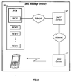
- Figure 6 illustrates a method of sending SMS messages to a client from the system.
- a user managed power system may comprise a powered user device at a first location; an interface at a second location remote from the first location and connected to the first location for data communication between the interface and the device with a security protocol; a power distribution device supplying power to the user device and in data communication with the user device and interface; and wherein the a command entered at the interface causes manipulation of the power supplied to the device.
- One embodiment of the present invention comprises an IP configurable and manageable power strip 10 as shown in FIG. 1 , although any IP configurable power strip is contemplated. Power is supplied to the strip, such as by cord 12.
- the configurable power strip 10 further comprises at least one communications port 14.
- the communications port may be adapted to provide support for both IEEE 802.3 compliant 10 Base T, 100 BaseT Ethernet and Gigabit Ethernet networks, or some other communication protocol.
- the communications port 10 is preferably a dual RJ-45 modular connector.
- the power strip 10 may be adapted to provide support as a powered device (PD) for Power-Over-Ethernet operation for the 10 Base T, 100 BaseT Ethernet and Gigabit Ethernet, or other communication protocol, port.
- the power strip is further comprised of at least one power socket 16.
- a commercial example of an IP configurable and manageable power strip is the MP Advanced power strips as sold by the Liebert Corporation. Monitoring and controlling of the MP Advanced power strips is accomplished using the OpenComms EM PDU or the Liebert IntelliSlot Asset Manager and IntelliRack, which includes a basic web interface.
- Another commercial embodiment is an MP Advanced power strip with the MP Advanced Access Server. Both products are available from Liebert Corporation.
- the Web interface of the MP Advanced Access Server offers summary status of the control module, power strip and each module installed in the access server. The Web interface also permits the user to access information about the individual power strips and controls for each receptacle on any power strip connected to the MP Advanced Access Server.
- FIG. 2 illustrates a typical setup at a data center.
- Data center 20 comprises multiple power strips 22 and 24. Each power strip is given an individual IP Address and is connected a communications protocol 26, such as the Internet, a Web, SNMP, or a local network. Each power strip comprises multiple power sockets 28.
- the data center further comprises a server 30, such as, but not limited to, an e-mail server. The server draws its power from the individual power sockets 32 and 34 of the power strips.
- the present invention allows the individual power sockets to be controlled remotely by the server user by the same method and security methodology as the user controls the server.
- the present invention allows for a power strip design that allows for the complete management of the power strip to be performed using the same security methodology employed by the server being powered. If the owner of a rack space in a data center has control access on, or privilege to, a piece of equipment, then the security software will enable them and grant them direct control of the particular power socket that supplies power to the system by the same method.
- SAN Storage Area Network
- Radius authentication server For example, and without limitation, if a Storage Area Network (SAN) is controlled and managed via a Radius authentication server, then this invention provides Web-based interface that ties the same SAN authentication to the power strip receptacle that supplies that product.
- SANs are distinguished from other forms of network storage by the low-level access method that they use. Access methods on SANs are very similar to those used for internal disk drives, like ATA and SCSI.
- a server issues a request for specific blocks, or data segments, from specific disk drives. This method is known as block storage.
- the device acts in a similar fashion to an internal drive, accessing the specified block, and sending the response across the network.
- RADIUS Authentication is known in the art.
- Remote Authentication Dial In User Service is an AAA (authentication, authorization and accounting) protocol for applications such as network access or IP mobility developed by Interlink Networks. It is intended to work in both local and roaming situations.
- Some ISPs commonly modem, DSL, or wireless 802.11 services
- NAS Network Access Server
- RADIUS server checks that the information is correct using authentication schemes like PAP, CHAP or EAP.
- the server will then authorize access to the ISP system and select an IP address, L2TP parameters, etc.
- the RADIUS server will also be notified if and when the session starts and stops, so that the user can be billed accordingly; or the data can be used for statistical purposes. Additionally RADIUS is widely used by VoIP service providers. It is used to pass login credentials of a SIP end point (like a broadband phone) to a SIP Registrar using digest authentication, and then to RADIUS server using RADIUS.
- Another embodiment of the present invention is adapted for a power socket running a Windows 2003 system.
- the load utilizing that socket is controlled by an Active Directory Secured Microsoft Windows Server.
- An Active Directory Secured Microsoft Windows Server is an implementation of LDAP directory services by Microsoft for use in Windows environments.
- An Active Directory Secured Microsoft Windows Server allows administrators to assign enterprise-wide policies, deploy programs to many computers, and apply critical updates to an entire organization.
- An Active Directory Secured Microsoft Windows Server stores information and settings relating to an organization in a central, organized, accessible database.
- An Active Directory Secured Microsoft Windows Server networks can vary from a small installation with a few hundred objects, to a large installation with millions of objects.
- the Active Directory Secured Microsoft Windows Server may be used to control and manage the power to the load.
- Kerberos Another typical security service that allows the consumer to control the power sockets is Kerberos, which is freely available from the Massachusetts Institute of Technology. Kerberos is a computer network authentication protocol, which allows individuals communicating over an insecure network to prove their identity to one another in a secure manner. Kerberos prevents eavesdropping or replay attacks, and ensures the integrity of the transmitted data. It provides mutual authentication - both the user and the server verify each other's identity. Kerberos builds on symmetric key cryptography and uses, as its basis, the Needham-Schroeder protocol. It makes use of a trusted third party, termed a Key Distribution Center (KDC), which consists of two logically separate parts: an Authentication Server (AS) and a Ticket Granting Server (TGS).
- KDC Key Distribution Center
- Kerberos works on the basis of "tickets" which serve to prove the identity of users. Kerberos maintains a database of secret keys; each entity on the network - whether a client or a server - shares a secret key known only to itself and to Kerberos. Knowledge of this key serves to prove an entity's identity. For communication between two entities, Kerberos generates a session key, which they can use to secure their interactions. In this embodiment of the invention the user access and control are managed by the Kerberos systems.
- Data center 50 comprises one or more power strips 52 and 54. Each power strip is given an individual IP Address and is connected a mid-level manager 56. The mid-level manager is in turn connected to a communications protocol 58, such as the Internet, a Web, SNMP, or a local network. Each power strip comprises multiple power sockets 60.
- the data center further comprises a server 62, such as, but not limited to, an e-mail server.
- the midlevel manager may consist of a serial interface card and a web card.
- the web card can provide web-management capability for enhanced communications and control.
- the mid-level manager allows the system of adaptive power strips to be operated over the network using a web browser running on a computer.
- the web interface can be used by a client computer running any modem operating system (e.g. Windows, Mac OS X, Linux, etc) since web browser programs are available for all of them.
- FIG. 3 illustrates an embodiment of a method utilizing the current invention.
- an administrator of an email server desires to control the power output of the email server.
- the administrator logs into the email server through a typical security protocol, such as Active Directory, RADIUS, or Kerberos.
- the administrator gains control over the email server. He is also given access to control the power socket to that server.
- the interface with the power control only shows the strips and the sockets associated with his email server.
- the administrator performs a reboot, such as by momentarily interrupting power to the email server, or other necessary power control and monitoring.
- Another advantage of the current invention is that systems utilizing this invention will not require personnel at the data center to be directly involved in the day to day operation of the power sockets running a piece of equipment.
- the security for controlling the power strip socket is kept up-to-date with the security access for the server or item managed. For example, if a user loses their access rights to a server, their access rights to control the power to the server are automatically removed also and kept synchronized with the power strips.
- a further embodiment of the current invention is a system that is able to notify the user of events, errors, and warnings via short message service (SMS) or email.
- Figure 5 is a block diagram that shows how an email message is sent to a recipient in a preferred embodiment. The following steps are taken to deliver an email message.
- the email is sent by the adaptable power strip 70 to the configured SMTP server 72.
- the SMTP server 72 delivers the email to the email server 74 specified in the email address.
- the email is delivered to an email account specified in the email address.
- the client computer 76 retrieves the email message from the mail server.
- POP3, Microsoft Exchange, and web interfaces are examples of how a client may retrieve an email message from the destination email server.
- FIG. 6 illustrates a block diagram that shows how a SMS message is sent to a mobile device.
- a SMS message is initiated by sending an email message to one or more configured email addresses. The following steps are taken to deliver a SMS message.
- the SMS email is sent by the adaptable power strip 80 to the configured SMTP server 82.
- the SMTP server 82 delivers the SMS email to the specified email address.
- This SMS email is delivered to an email account monitored by a SMS Center 84.
- the SMS Center 84 delivers the SMS message to the mobile device specified in the "to" address of the SMS email.
Landscapes
- Engineering & Computer Science (AREA)
- Theoretical Computer Science (AREA)
- Computer Hardware Design (AREA)
- General Engineering & Computer Science (AREA)
- Computer Security & Cryptography (AREA)
- Physics & Mathematics (AREA)
- General Physics & Mathematics (AREA)
- Software Systems (AREA)
- Microelectronics & Electronic Packaging (AREA)
- Power Sources (AREA)
- Remote Monitoring And Control Of Power-Distribution Networks (AREA)
- Cable Transmission Systems, Equalization Of Radio And Reduction Of Echo (AREA)
- Small-Scale Networks (AREA)
Claims (10)
- Procédé de gestion de l'alimentation vers un dispositif de serveur à distance comprenant les étapes consistant à :permettre à un administrateur de commander le serveur lorsque l'administrateur se connecte au serveur en utilisant un protocole de sécurité ;permettre en outre à l'administrateur de commander une prise d'alimentation d'une barre d'alimentation,la prise d'alimentation étant associée au serveur, lorsque l'administrateur se connecte au serveur en utilisant le protocole de sécurité ;autoriser l'administrateur à commander et contrôler l'alimentation au serveur via la prise d'alimentation associée au serveur ; etgarder un accès de sécurité à la prise d'alimentation de la barre d'alimentation à jour avec un accès de sécurité au serveur.
- Procédé selon la revendication 1, dans lequel le serveur est un serveur d'ordinateur ou un serveur d'hébergement Web.
- Procédé selon la revendication 1, dans lequel la commande et le contrôle de l'alimentation comprend la désactivation puis l'activation ou la désactivation ensuite de l'alimentation fournie au serveur.
- Procédé selon la revendication 1, dans lequel le protocole de sécurité est Kerberos ; ou dans lequel le protocole de sécurité est Active Desktop ; ou dans lequel le protocole de sécurité est un protocole de sécurité externe tel que RADIUS.
- Procédé selon la revendication 1, dans lequel l'administrateur ne voit que la barre d'alimentation et la prise d'alimentation associées au serveur auquel l'administrateur s'est connecté.
- Procédé selon la revendication 5, dans lequel la commande et le contrôle de l'alimentation comprennent la désactivation puis l'activation ou la désactivation ensuite de l'alimentation fournie au serveur.
- Procédé selon la revendication 1, comprenant en outre le retrait automatique des droits d'accès d'un utilisateur de commander l'alimentation au serveur lorsque l'utilisateur perd ses droits d'accès au serveur.
- Système d'alimentation géré par l'utilisateur comprenant :un serveur administré par un administrateur ;une barre d'alimentation configurée pour recevoir une demande de l'administrateur qu'une action soit réalisée par rapport à l'alimentation qui est fournie au serveur ;des prises d'alimentations individuelles sur la barre d'alimentation, la barre d'alimentation étant en outre configurée pour permettre aux prises d'alimentations individuelles d'être commandées à distance par un utilisateur, comprenant la réalisation d'un redémarrage hors tension du serveur, en utilisant le même protocole de sécurité que le protocole de sécurité que l'utilisateur utilise pour commander le serveur.
- Système d'alimentation géré par l'utilisateur selon la revendication 8, dans lequel le serveur est un serveur de courrier électronique.
- Système d'alimentation géré par l'utilisateur selon la revendication 8, dans lequel le protocole de sécurité est Kerberos ; ou dans lequel le protocole de sécurité est Active Desktop ; ou dans lequel le protocole de sécurité est un protocole de sécurité externe, tel que RADIUS.
Applications Claiming Priority (2)
| Application Number | Priority Date | Filing Date | Title |
|---|---|---|---|
| US86921506P | 2006-12-08 | 2006-12-08 | |
| PCT/US2007/086809 WO2008073833A2 (fr) | 2006-12-08 | 2007-12-07 | Système d'alimentation géré par utilisateur comportant une sécurité |
Publications (2)
| Publication Number | Publication Date |
|---|---|
| EP2095203A2 EP2095203A2 (fr) | 2009-09-02 |
| EP2095203B1 true EP2095203B1 (fr) | 2013-02-13 |
Family
ID=39431004
Family Applications (1)
| Application Number | Title | Priority Date | Filing Date |
|---|---|---|---|
| EP20070869041 Active EP2095203B1 (fr) | 2006-12-08 | 2007-12-07 | Système d'alimentation géré par utilisateur comportant une sécurité |
Country Status (3)
| Country | Link |
|---|---|
| US (1) | US8450874B2 (fr) |
| EP (1) | EP2095203B1 (fr) |
| WO (1) | WO2008073833A2 (fr) |
Families Citing this family (20)
| Publication number | Priority date | Publication date | Assignee | Title |
|---|---|---|---|---|
| WO2009117500A2 (fr) * | 2008-03-19 | 2009-09-24 | Liebert Corporation | Bande d'alimentation adaptative |
| US20230132380A9 (en) * | 2008-03-26 | 2023-04-27 | Zonit Structured Solutions, Llc | Power distribution systems and methodology |
| WO2009124053A1 (fr) * | 2008-03-31 | 2009-10-08 | Panduit Corp. | Unité de prise de courant |
| US9178768B2 (en) * | 2009-01-07 | 2015-11-03 | Ixia | Methods, systems, and computer readable media for combining voice over internet protocol (VoIP) call data with geographical information |
| GB0910025D0 (en) * | 2009-06-10 | 2009-07-22 | Bgm Group The Ltd | Apparatus and method for power management |
| WO2012011982A2 (fr) * | 2010-04-07 | 2012-01-26 | The Wiremold Company | Systèmes de bus personnalisable |
| US9640960B2 (en) | 2010-04-07 | 2017-05-02 | The Wiremold Company | Customizable bus systems |
| US8627118B2 (en) | 2010-05-24 | 2014-01-07 | International Business Machines Corporation | Chassis power allocation using expedited power permissions |
| US10205319B2 (en) | 2010-06-11 | 2019-02-12 | Eaton Intelligent Power Limited | Automatic matching of sources to loads |
| US8805998B2 (en) | 2010-06-11 | 2014-08-12 | Eaton Corporation | Automatic matching of sources to loads |
| CN201904797U (zh) * | 2010-12-20 | 2011-07-20 | 特通科技有限公司 | 具有开关功能的网络连接器模块 |
| CA2830283C (fr) | 2011-03-25 | 2016-11-01 | Certicom Corp. | Interrogation d'un dispositif d'authentification |
| EP2705725B1 (fr) | 2011-05-06 | 2017-07-19 | Certicom Corp. | Gestion de données pour dispositifs d'authentification |
| US8949053B2 (en) | 2011-07-29 | 2015-02-03 | Schneider Electric It Corporation | Systems and methods for current and voltage monitoring |
| US9800031B2 (en) * | 2012-07-26 | 2017-10-24 | Server Technology, Inc. | Multi-position input cord assembly for a power distribution unit |
| AU2013295604B2 (en) | 2012-07-26 | 2016-06-23 | Chris CONNOLLY | Multi-position input cord assembly for a power distribution unit |
| US9369290B2 (en) * | 2012-11-30 | 2016-06-14 | Certicom Corp. | Challenge-response authentication using a masked response value |
| US9727720B2 (en) | 2012-11-30 | 2017-08-08 | Certicom Corp. | Challenge-response authentication using a masked response value |
| US9736051B2 (en) | 2014-04-30 | 2017-08-15 | Ixia | Smartap arrangement and methods thereof |
| US9804210B2 (en) | 2015-08-31 | 2017-10-31 | Comcast Cable Communications, Llc | Authentication, authorization, and/or accounting of power-consuming devices |
Family Cites Families (28)
| Publication number | Priority date | Publication date | Assignee | Title |
|---|---|---|---|---|
| US5281859A (en) * | 1991-06-13 | 1994-01-25 | Molex Incorporated | Automatically switched power receptacle |
| WO1993010615A1 (fr) | 1991-11-15 | 1993-05-27 | Server Technology, Inc. | Systeme servant a proteger et a faire redemarrer des ordinateurs et des peripheriques a des endroits eloignes accessibles par communication telephonique |
| US5424903A (en) * | 1993-01-12 | 1995-06-13 | Tandy Corporation | Intelligent power switcher |
| US7099934B1 (en) * | 1996-07-23 | 2006-08-29 | Ewing Carrel W | Network-connecting power manager for remote appliances |
| US6711613B1 (en) * | 1996-07-23 | 2004-03-23 | Server Technology, Inc. | Remote power control system |
| US7171461B2 (en) * | 1996-07-23 | 2007-01-30 | Server Technology, Inc. | Network remote power management outlet strip |
| US7043543B2 (en) * | 1996-07-23 | 2006-05-09 | Server Technology, Inc. | Vertical-mount electrical power distribution plugstrip |
| US5862393A (en) * | 1996-10-07 | 1999-01-19 | Lxe, Inc. | System for managing power of a computer with removable devices |
| US5901067A (en) * | 1996-11-15 | 1999-05-04 | Kim Y. Kao | System for interactively selecting and activating groups of electrically powered devices |
| US20020057206A1 (en) | 1999-05-11 | 2002-05-16 | Charles H. Reynolds | Method and appparatus for an improved remotely switchable power supply |
| US6410994B1 (en) * | 1999-05-11 | 2002-06-25 | Fellowes Manufacturing Company | Modular power strip |
| DE19942465C2 (de) | 1999-09-06 | 2002-12-05 | Phoenix Contact Gmbh & Co | Verfahren zur Vergabe von IP-Adressen in Kommunikationsnetzen |
| US6608406B2 (en) * | 1999-12-21 | 2003-08-19 | S+S Power Engineering | Rack mountable power distribution apparatus |
| TW459425B (en) * | 2000-06-23 | 2001-10-11 | Primax Electronics Ltd | Power socket apparatus |
| US6741442B1 (en) * | 2000-10-13 | 2004-05-25 | American Power Conversion Corporation | Intelligent power distribution system |
| US6937461B1 (en) * | 2001-11-28 | 2005-08-30 | Donahue, Iv William F. | Modular power distribution unit, module for the power distribution unit, and method of using the same |
| US6744150B2 (en) * | 2001-12-03 | 2004-06-01 | Neven V. Rendic | Outlet strip controlled by PC using low voltage powertap |
| US6724315B2 (en) * | 2002-01-02 | 2004-04-20 | International Business Machines Corporation | Identification of mounting locations of sub-systems in mounting units |
| US6826036B2 (en) * | 2002-06-28 | 2004-11-30 | Hewlett-Packard Development Company, L.P. | Modular power distribution system for use in computer equipment racks |
| US6785142B1 (en) * | 2003-02-26 | 2004-08-31 | Dell Products L.P. | System and method for detecting blank modules |
| US6796506B1 (en) * | 2003-03-10 | 2004-09-28 | Hewlett-Packard Development Company, L.P. | Tracking electronic devices |
| TWM245684U (en) * | 2003-07-21 | 2004-10-01 | Rocom Electric Company Ltd | Power protection device capable of being controlled via IP address |
| TW200505186A (en) * | 2003-07-21 | 2005-02-01 | Rocom Electric Company Ltd | Control system implementing control over power protector via IP address |
| JP3918827B2 (ja) * | 2004-01-21 | 2007-05-23 | 株式会社日立製作所 | セキュアリモートアクセスシステム |
| US7196900B2 (en) | 2004-05-21 | 2007-03-27 | Server Technology, Inc. | Adaptable rack mountable power distribution apparatus |
| US7268998B2 (en) * | 2004-11-01 | 2007-09-11 | Server Technology, Inc. | Ganged outlet power distribution apparatus |
| US20070089163A1 (en) * | 2005-10-18 | 2007-04-19 | International Business Machines Corporation | System and method for controlling security of a remote network power device |
| US7280931B1 (en) * | 2006-05-18 | 2007-10-09 | International Business Machines Corporation | Method and system for calibrating an electrical device |
-
2007
- 2007-12-07 EP EP20070869041 patent/EP2095203B1/fr active Active
- 2007-12-07 WO PCT/US2007/086809 patent/WO2008073833A2/fr not_active Ceased
- 2007-12-07 US US11/952,756 patent/US8450874B2/en active Active
Also Published As
| Publication number | Publication date |
|---|---|
| WO2008073833A2 (fr) | 2008-06-19 |
| WO2008073833A3 (fr) | 2008-07-31 |
| US20080136607A1 (en) | 2008-06-12 |
| US8450874B2 (en) | 2013-05-28 |
| EP2095203A2 (fr) | 2009-09-02 |
Similar Documents
| Publication | Publication Date | Title |
|---|---|---|
| EP2095203B1 (fr) | Système d'alimentation géré par utilisateur comportant une sécurité | |
| US8898315B2 (en) | Remote access to resources | |
| EP2442492B1 (fr) | Système et procédé pour la gestion distribuée d'ordinateurs partagés | |
| JP4709214B2 (ja) | データネットワークのノードに対するアウトオブバンド・アクセスを統合化し安全化し自動化するシステム及び方法 | |
| KR101883146B1 (ko) | 서비스로서 디바이스들을 제공하는 방법 | |
| US20110055367A1 (en) | Serial port forwarding over secure shell for secure remote management of networked devices | |
| US20030041085A1 (en) | Management system and method for network devices using information recordable medium | |
| US20110055899A1 (en) | Secure remote management of network devices with local processing and secure shell for remote distribution of information | |
| WO2003100638A1 (fr) | Systemes de gestion de ressources de reseaux | |
| CN101488857B (zh) | 认证服务虚拟化 | |
| US20210377018A1 (en) | Secure remote access to industrial control systems using hardware based authentication | |
| WO2003100563A2 (fr) | Gestionnaire de mise a jour de reseau | |
| US8365253B2 (en) | Method and system for secure management of co-located customer premises equipment | |
| EP1724701A2 (fr) | Solution aux problèmes concernant les logiciels malveillants dans l'internet | |
| EP3698519B1 (fr) | Système et procédé de communication avec un processeur de service | |
| CN113709157A (zh) | 基于云路由和安全控制中心的电力安全研发网络结构 | |
| JP2026031038A (ja) | ネットワーク接続システムおよびネットワークに接続可能なlan収容装置 | |
| Tanwongsval | Sun Ray™ Thin-Client and Smart Cards: An Old Concept With New Muscle | |
| David | The Internet—Gateway to your information assets | |
| Greene | 3Com quarantines malicious traffic | |
| Gunderson | Network security for a communications company | |
| HK1096740A (en) | Solution to the malware problems of the internet |
Legal Events
| Date | Code | Title | Description |
|---|---|---|---|
| PUAI | Public reference made under article 153(3) epc to a published international application that has entered the european phase |
Free format text: ORIGINAL CODE: 0009012 |
|
| 17P | Request for examination filed |
Effective date: 20090708 |
|
| AK | Designated contracting states |
Kind code of ref document: A2 Designated state(s): AT BE BG CH CY CZ DE DK EE ES FI FR GB GR HU IE IS IT LI LT LU LV MC MT NL PL PT RO SE SI SK TR |
|
| DAX | Request for extension of the european patent (deleted) | ||
| 17Q | First examination report despatched |
Effective date: 20100407 |
|
| GRAP | Despatch of communication of intention to grant a patent |
Free format text: ORIGINAL CODE: EPIDOSNIGR1 |
|
| GRAS | Grant fee paid |
Free format text: ORIGINAL CODE: EPIDOSNIGR3 |
|
| GRAA | (expected) grant |
Free format text: ORIGINAL CODE: 0009210 |
|
| AK | Designated contracting states |
Kind code of ref document: B1 Designated state(s): AT BE BG CH CY CZ DE DK EE ES FI FR GB GR HU IE IS IT LI LT LU LV MC MT NL PL PT RO SE SI SK TR |
|
| REG | Reference to a national code |
Ref country code: GB Ref legal event code: FG4D |
|
| REG | Reference to a national code |
Ref country code: AT Ref legal event code: REF Ref document number: 596809 Country of ref document: AT Kind code of ref document: T Effective date: 20130215 |
|
| REG | Reference to a national code |
Ref country code: IE Ref legal event code: FG4D |
|
| REG | Reference to a national code |
Ref country code: DE Ref legal event code: R096 Ref document number: 602007028489 Country of ref document: DE Effective date: 20130411 |
|
| REG | Reference to a national code |
Ref country code: AT Ref legal event code: MK05 Ref document number: 596809 Country of ref document: AT Kind code of ref document: T Effective date: 20130213 |
|
| REG | Reference to a national code |
Ref country code: NL Ref legal event code: VDEP Effective date: 20130213 |
|
| REG | Reference to a national code |
Ref country code: LT Ref legal event code: MG4D |
|
| PG25 | Lapsed in a contracting state [announced via postgrant information from national office to epo] |
Ref country code: IS Free format text: LAPSE BECAUSE OF FAILURE TO SUBMIT A TRANSLATION OF THE DESCRIPTION OR TO PAY THE FEE WITHIN THE PRESCRIBED TIME-LIMIT Effective date: 20130613 Ref country code: LT Free format text: LAPSE BECAUSE OF FAILURE TO SUBMIT A TRANSLATION OF THE DESCRIPTION OR TO PAY THE FEE WITHIN THE PRESCRIBED TIME-LIMIT Effective date: 20130213 Ref country code: BG Free format text: LAPSE BECAUSE OF FAILURE TO SUBMIT A TRANSLATION OF THE DESCRIPTION OR TO PAY THE FEE WITHIN THE PRESCRIBED TIME-LIMIT Effective date: 20130513 Ref country code: AT Free format text: LAPSE BECAUSE OF FAILURE TO SUBMIT A TRANSLATION OF THE DESCRIPTION OR TO PAY THE FEE WITHIN THE PRESCRIBED TIME-LIMIT Effective date: 20130213 Ref country code: ES Free format text: LAPSE BECAUSE OF FAILURE TO SUBMIT A TRANSLATION OF THE DESCRIPTION OR TO PAY THE FEE WITHIN THE PRESCRIBED TIME-LIMIT Effective date: 20130524 Ref country code: SE Free format text: LAPSE BECAUSE OF FAILURE TO SUBMIT A TRANSLATION OF THE DESCRIPTION OR TO PAY THE FEE WITHIN THE PRESCRIBED TIME-LIMIT Effective date: 20130213 |
|
| PG25 | Lapsed in a contracting state [announced via postgrant information from national office to epo] |
Ref country code: LV Free format text: LAPSE BECAUSE OF FAILURE TO SUBMIT A TRANSLATION OF THE DESCRIPTION OR TO PAY THE FEE WITHIN THE PRESCRIBED TIME-LIMIT Effective date: 20130213 Ref country code: PT Free format text: LAPSE BECAUSE OF FAILURE TO SUBMIT A TRANSLATION OF THE DESCRIPTION OR TO PAY THE FEE WITHIN THE PRESCRIBED TIME-LIMIT Effective date: 20130613 Ref country code: SI Free format text: LAPSE BECAUSE OF FAILURE TO SUBMIT A TRANSLATION OF THE DESCRIPTION OR TO PAY THE FEE WITHIN THE PRESCRIBED TIME-LIMIT Effective date: 20130213 Ref country code: PL Free format text: LAPSE BECAUSE OF FAILURE TO SUBMIT A TRANSLATION OF THE DESCRIPTION OR TO PAY THE FEE WITHIN THE PRESCRIBED TIME-LIMIT Effective date: 20130213 Ref country code: BE Free format text: LAPSE BECAUSE OF FAILURE TO SUBMIT A TRANSLATION OF THE DESCRIPTION OR TO PAY THE FEE WITHIN THE PRESCRIBED TIME-LIMIT Effective date: 20130213 Ref country code: FI Free format text: LAPSE BECAUSE OF FAILURE TO SUBMIT A TRANSLATION OF THE DESCRIPTION OR TO PAY THE FEE WITHIN THE PRESCRIBED TIME-LIMIT Effective date: 20130213 Ref country code: GR Free format text: LAPSE BECAUSE OF FAILURE TO SUBMIT A TRANSLATION OF THE DESCRIPTION OR TO PAY THE FEE WITHIN THE PRESCRIBED TIME-LIMIT Effective date: 20130514 |
|
| PG25 | Lapsed in a contracting state [announced via postgrant information from national office to epo] |
Ref country code: SK Free format text: LAPSE BECAUSE OF FAILURE TO SUBMIT A TRANSLATION OF THE DESCRIPTION OR TO PAY THE FEE WITHIN THE PRESCRIBED TIME-LIMIT Effective date: 20130213 Ref country code: RO Free format text: LAPSE BECAUSE OF FAILURE TO SUBMIT A TRANSLATION OF THE DESCRIPTION OR TO PAY THE FEE WITHIN THE PRESCRIBED TIME-LIMIT Effective date: 20130213 Ref country code: NL Free format text: LAPSE BECAUSE OF FAILURE TO SUBMIT A TRANSLATION OF THE DESCRIPTION OR TO PAY THE FEE WITHIN THE PRESCRIBED TIME-LIMIT Effective date: 20130213 Ref country code: CZ Free format text: LAPSE BECAUSE OF FAILURE TO SUBMIT A TRANSLATION OF THE DESCRIPTION OR TO PAY THE FEE WITHIN THE PRESCRIBED TIME-LIMIT Effective date: 20130213 Ref country code: EE Free format text: LAPSE BECAUSE OF FAILURE TO SUBMIT A TRANSLATION OF THE DESCRIPTION OR TO PAY THE FEE WITHIN THE PRESCRIBED TIME-LIMIT Effective date: 20130213 Ref country code: DK Free format text: LAPSE BECAUSE OF FAILURE TO SUBMIT A TRANSLATION OF THE DESCRIPTION OR TO PAY THE FEE WITHIN THE PRESCRIBED TIME-LIMIT Effective date: 20130213 |
|
| PLBE | No opposition filed within time limit |
Free format text: ORIGINAL CODE: 0009261 |
|
| STAA | Information on the status of an ep patent application or granted ep patent |
Free format text: STATUS: NO OPPOSITION FILED WITHIN TIME LIMIT |
|
| PG25 | Lapsed in a contracting state [announced via postgrant information from national office to epo] |
Ref country code: IT Free format text: LAPSE BECAUSE OF FAILURE TO SUBMIT A TRANSLATION OF THE DESCRIPTION OR TO PAY THE FEE WITHIN THE PRESCRIBED TIME-LIMIT Effective date: 20130213 |
|
| 26N | No opposition filed |
Effective date: 20131114 |
|
| REG | Reference to a national code |
Ref country code: DE Ref legal event code: R097 Ref document number: 602007028489 Country of ref document: DE Effective date: 20131114 |
|
| REG | Reference to a national code |
Ref country code: CH Ref legal event code: PL |
|
| PG25 | Lapsed in a contracting state [announced via postgrant information from national office to epo] |
Ref country code: MC Free format text: LAPSE BECAUSE OF FAILURE TO SUBMIT A TRANSLATION OF THE DESCRIPTION OR TO PAY THE FEE WITHIN THE PRESCRIBED TIME-LIMIT Effective date: 20130213 Ref country code: LU Free format text: LAPSE BECAUSE OF FAILURE TO SUBMIT A TRANSLATION OF THE DESCRIPTION OR TO PAY THE FEE WITHIN THE PRESCRIBED TIME-LIMIT Effective date: 20131207 |
|
| REG | Reference to a national code |
Ref country code: IE Ref legal event code: MM4A |
|
| REG | Reference to a national code |
Ref country code: FR Ref legal event code: ST Effective date: 20140829 |
|
| PG25 | Lapsed in a contracting state [announced via postgrant information from national office to epo] |
Ref country code: IE Free format text: LAPSE BECAUSE OF NON-PAYMENT OF DUE FEES Effective date: 20131207 Ref country code: CH Free format text: LAPSE BECAUSE OF NON-PAYMENT OF DUE FEES Effective date: 20131231 Ref country code: LI Free format text: LAPSE BECAUSE OF NON-PAYMENT OF DUE FEES Effective date: 20131231 |
|
| PG25 | Lapsed in a contracting state [announced via postgrant information from national office to epo] |
Ref country code: FR Free format text: LAPSE BECAUSE OF NON-PAYMENT OF DUE FEES Effective date: 20131231 |
|
| PG25 | Lapsed in a contracting state [announced via postgrant information from national office to epo] |
Ref country code: CY Free format text: LAPSE BECAUSE OF FAILURE TO SUBMIT A TRANSLATION OF THE DESCRIPTION OR TO PAY THE FEE WITHIN THE PRESCRIBED TIME-LIMIT Effective date: 20130213 Ref country code: TR Free format text: LAPSE BECAUSE OF FAILURE TO SUBMIT A TRANSLATION OF THE DESCRIPTION OR TO PAY THE FEE WITHIN THE PRESCRIBED TIME-LIMIT Effective date: 20130213 |
|
| PG25 | Lapsed in a contracting state [announced via postgrant information from national office to epo] |
Ref country code: HU Free format text: LAPSE BECAUSE OF FAILURE TO SUBMIT A TRANSLATION OF THE DESCRIPTION OR TO PAY THE FEE WITHIN THE PRESCRIBED TIME-LIMIT; INVALID AB INITIO Effective date: 20071207 |
|
| PG25 | Lapsed in a contracting state [announced via postgrant information from national office to epo] |
Ref country code: MT Free format text: LAPSE BECAUSE OF FAILURE TO SUBMIT A TRANSLATION OF THE DESCRIPTION OR TO PAY THE FEE WITHIN THE PRESCRIBED TIME-LIMIT Effective date: 20130213 |
|
| REG | Reference to a national code |
Ref country code: DE Ref legal event code: R082 Ref document number: 602007028489 Country of ref document: DE Representative=s name: WESTPHAL, MUSSGNUG & PARTNER PATENTANWAELTE MI, DE Ref country code: DE Ref legal event code: R081 Ref document number: 602007028489 Country of ref document: DE Owner name: VERTIV CORP., COLUMBUS, US Free format text: FORMER OWNER: LIEBERT CORPORATION, COLUMBUS, OH 43085, US |
|
| P01 | Opt-out of the competence of the unified patent court (upc) registered |
Effective date: 20230621 |
|
| PGFP | Annual fee paid to national office [announced via postgrant information from national office to epo] |
Ref country code: GB Payment date: 20251229 Year of fee payment: 19 |
|
| PGFP | Annual fee paid to national office [announced via postgrant information from national office to epo] |
Ref country code: DE Payment date: 20251229 Year of fee payment: 19 |