EP2095441B1 - Entraînement à ultrasons - Google Patents
Entraînement à ultrasons Download PDFInfo
- Publication number
- EP2095441B1 EP2095441B1 EP07847102A EP07847102A EP2095441B1 EP 2095441 B1 EP2095441 B1 EP 2095441B1 EP 07847102 A EP07847102 A EP 07847102A EP 07847102 A EP07847102 A EP 07847102A EP 2095441 B1 EP2095441 B1 EP 2095441B1
- Authority
- EP
- European Patent Office
- Prior art keywords
- layers
- friction
- oscillator
- elastic
- drive according
- Prior art date
- Legal status (The legal status is an assumption and is not a legal conclusion. Google has not performed a legal analysis and makes no representation as to the accuracy of the status listed.)
- Active
Links
Images








Classifications
-
- H—ELECTRICITY
- H02—GENERATION; CONVERSION OR DISTRIBUTION OF ELECTRIC POWER
- H02N—ELECTRIC MACHINES NOT OTHERWISE PROVIDED FOR
- H02N2/00—Electric machines in general using piezoelectric effect, electrostriction or magnetostriction
- H02N2/0005—Electric machines in general using piezoelectric effect, electrostriction or magnetostriction producing non-specific motion; Details common to machines covered by H02N2/02 - H02N2/16
- H02N2/005—Mechanical details, e.g. housings
- H02N2/0065—Friction interface
-
- H—ELECTRICITY
- H02—GENERATION; CONVERSION OR DISTRIBUTION OF ELECTRIC POWER
- H02N—ELECTRIC MACHINES NOT OTHERWISE PROVIDED FOR
- H02N2/00—Electric machines in general using piezoelectric effect, electrostriction or magnetostriction
- H02N2/0005—Electric machines in general using piezoelectric effect, electrostriction or magnetostriction producing non-specific motion; Details common to machines covered by H02N2/02 - H02N2/16
- H02N2/005—Mechanical details, e.g. housings
- H02N2/0055—Supports for driving or driven bodies; Means for pressing driving body against driven body
-
- H—ELECTRICITY
- H02—GENERATION; CONVERSION OR DISTRIBUTION OF ELECTRIC POWER
- H02N—ELECTRIC MACHINES NOT OTHERWISE PROVIDED FOR
- H02N2/00—Electric machines in general using piezoelectric effect, electrostriction or magnetostriction
- H02N2/0005—Electric machines in general using piezoelectric effect, electrostriction or magnetostriction producing non-specific motion; Details common to machines covered by H02N2/02 - H02N2/16
- H02N2/005—Mechanical details, e.g. housings
- H02N2/0055—Supports for driving or driven bodies; Means for pressing driving body against driven body
- H02N2/006—Elastic elements, e.g. springs
-
- H—ELECTRICITY
- H02—GENERATION; CONVERSION OR DISTRIBUTION OF ELECTRIC POWER
- H02N—ELECTRIC MACHINES NOT OTHERWISE PROVIDED FOR
- H02N2/00—Electric machines in general using piezoelectric effect, electrostriction or magnetostriction
- H02N2/02—Electric machines in general using piezoelectric effect, electrostriction or magnetostriction producing linear motion, e.g. actuators; Linear positioners ; Linear motors
- H02N2/026—Electric machines in general using piezoelectric effect, electrostriction or magnetostriction producing linear motion, e.g. actuators; Linear positioners ; Linear motors by pressing one or more vibrators against the driven body
-
- H—ELECTRICITY
- H02—GENERATION; CONVERSION OR DISTRIBUTION OF ELECTRIC POWER
- H02N—ELECTRIC MACHINES NOT OTHERWISE PROVIDED FOR
- H02N2/00—Electric machines in general using piezoelectric effect, electrostriction or magnetostriction
- H02N2/02—Electric machines in general using piezoelectric effect, electrostriction or magnetostriction producing linear motion, e.g. actuators; Linear positioners ; Linear motors
- H02N2/06—Drive circuits; Control arrangements or methods
- H02N2/065—Large signal circuits, e.g. final stages
-
- H—ELECTRICITY
- H02—GENERATION; CONVERSION OR DISTRIBUTION OF ELECTRIC POWER
- H02N—ELECTRIC MACHINES NOT OTHERWISE PROVIDED FOR
- H02N2/00—Electric machines in general using piezoelectric effect, electrostriction or magnetostriction
- H02N2/10—Electric machines in general using piezoelectric effect, electrostriction or magnetostriction producing rotary motion, e.g. rotary motors
- H02N2/103—Electric machines in general using piezoelectric effect, electrostriction or magnetostriction producing rotary motion, e.g. rotary motors by pressing one or more vibrators against the rotor
Definitions
- the invention belongs to the field of high precision linear and rotary ultrasonic systems and can be used in microscope stages, in integrated circuit manufacturing tables, in precise optical systems, and in other devices where high positioning accuracy and smooth running (uniformity of movement) are required become.
- Ultrasonic drive systems are known (eg. DE 199 38 954 A1 ), in which an ultrasonic oscillator causes the movement of a movable platform.
- a friction layer is placed directly on the side surface of the platform. Between the side surface of the platform and the friction layer is a damping layer.
- the disadvantage of such a system is that the thin damping layer can not completely decouple the platform from the vibrating ultrasonic oscillator. Therefore, ultrasonic waves are generated in the platform, which can propagate in it. These waves cause vibrations of the surface of the platform. It is not possible to bring the vibration amplitude of the surface below 50 nanometers. This makes it impossible to more accurately determine the position of the moving platform. This reduces the positioning accuracy of the moving platform and deteriorates the smoothness. This is particularly true at low speeds of the moving platform.
- the propagating in the moving platform ultrasonic wave causes an energy drain of the ultrasonic oscillator. This leads to additional energy losses.
- the ultrasonic wave entering the ball bearing generates low-frequency vibrations of the balls in the bearing. This leads to low-frequency acoustic noise through the ball bearing.
- an ultrasonic drive system (see EP 1 267 425 A2 ), in which the ultrasonic oscillator causes movement of the movable platform with damping openings in it.
- the apertures may be elongated, round, oval or otherwise, and prevent the propagation of ultrasonic waves in the platform.
- a disadvantage of this drive system is that the damping openings worsen the constancy of the force generated by the ultrasonic oscillator.
- a disadvantage of this drive system is, as in the previous case, that because of the transverse grooves, the force generated by the ultrasonic oscillator is variable.
- the object of the invention is to provide an improved ultrasonic actuator which offers one or more of the following advantages: increased positioning accuracy, improved smoothness (uniformity of movement), higher focusing accuracy of the optical system, longer life, reduced power consumption, lower generated noise and the ability to build stable excitation devices of the oscillators, which operate as self-exciting generators.
- the invention includes the idea of providing a high-precision ultrasonic drive in such a structural design that by special constructions of its main parts it is possible to realize a complete isolation of the movable holding device and the other drive parts from the ultrasonic vibrations, the high resolution (accuracy) of the drive is maintained.
- the thin elastic plate of the central layer may be made of, for example, steel, beryllium bronze, durable plastic or another elastic material
- the friction layers are made as thin plates of oxide ceramics, metal ceramics, monocrystalline material, heat treated steel or other abrasion resistant material
- the viscous layers are made as layers of adhesive rubber, viscous adhesive polymer material, adhesive paper or other viscous adhesive material
- the friction layers as thin plates made of oxide ceramics, metal ceramics, monocrystalline material, heat-treated steel or other abrasion-resistant material
- the elastic layers are designed as plates or rings of steel, titanium, copper, aluminum, oxide ceramics or other elastic material.
- the elastic layers may be parts of the friction layers. This simplifies the drive design.
- each of the ultrasonic oscillators may be disposed in opposed resilient mounts, the outer portions of which hold the ultrasonic oscillator at its opposite end surfaces in its maximum vibration velocities, the central portions of the elastic supports being fixed to the oscillator support, and wherein elastic supports are designed so that increases the cross-sectional area of each carrier from the outer part of the carrier towards the central part of the carrier. This prevents ultrasonic vibrations of the base plate of the drive.
- each of the oscillators can be mounted in two or four elastic support frames arranged in parallel with the side surfaces of the oscillator, each support frame being fixed to the side surface of the piezoelectric plate at minimum of its oscillation speeds and the oscillator support , This prevents ultrasonic vibrations in the base plate of the drive and significantly improves the transverse stability of the ultrasonic oscillators.
- the exciting device of the ultrasonic oscillators may be designed as a self-exciting generator whose excitation frequency is predetermined by the mechanical parameters of one of the active ultrasonic oscillators, the other ultrasonic oscillators being connected to the excitation device as passive elements. This increases the functional stability of the drive.
- the excitation device may be equipped with an analog controlled PWM DC converter.
- an analog controlled PWM DC converter As a result, the realization of an analog control for the drive is possible.
- the self-exciting generator of the exciter device may include a balanced PWM controller or an analog controlled symmetrical phase shifting controller. This increases the speed of the drive.
- the high-precision ultrasonic actuator can be equipped with a high-resolution measuring system and a processor controller for position or speed of the movable holder. This allows a high precision positioning or a high precision stable speed of the drive.
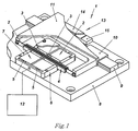
- a high-precision ultrasonic drive 1 (see Fig. 1 ) consists of two or more oppositely arranged identical ultrasonic oscillators 2 with friction elements 3. Between the ultrasonic oscillators 2 is a multi-layer friction rail 4, to which by means of elastic elements 5, the friction elements 3 of the oscillators 2 are pressed. The oscillators 2 are arranged in a holder 6 and are held in the longitudinal direction of walls 7.
- the drive 1 comprises a base plate 8, on which one or more guide rails 9 are arranged with one or more slides 10, the are connected to the movable holding device 11.
- the holding device 11 is used for arrangement or attachment of the displaceable parts (in the Fig. 1 Not shown).
- the drive has an excitation device 12.
- the drive 1 can also, as in Fig. 1 shown, a high-resolution measuring system 13 with a measuring ruler 14 and a read head 15 include.
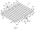
- the friction rail 4 consists of an odd number of longitudinally arranged alternating layers 16.
- a thin elastic plate 18 represents the central layer 17.
- the two outer layers 19 constitute frictional layers in the form of plates 20.
- the plate 18 has on the two opposite sides 23 attachment points 24, at which the friction rail 4 with the movable holding device 11th is attached.
- a variant of the invention provides a rotating construction (in Fig. 1 and 2 Not shown).
- the friction rail 4 has a multilayer ring (see Fig. 3 ), in which the central layer 17 as a thin elastic disk 25 and the friction layers 19, the viscous layers 21 and the elastic layers 22 as rings 26, 27, 28 are executed.
- the plate 18 or disk 25 (as the respective central layer 17) is made of steel, beryllium bronze, elastic plastic or other elastic material.
- the thickness of the plate 18 or the disk 25 is selected to be approximately equal to 0.01 ⁇ , wherein the length ⁇ is the excited in the oscillator 2 ultrasonic wave.
- the plates 20 or the rings 26 are made of oxide ceramics, metal ceramics, monocrystalline material, heat-treated steel or other abrasion-resistant material.
- the thickness of the plates 20 or discs 26 is selected to be approximately equal to 0.1 ⁇ .
- the viscous layers 21 (27) are made as layers of adhesive rubber, viscous adhesive polymeric material, adhesive paper tapes, or any other viscous adhesive material.
- the thickness of the viscous layers 21 (27) is selected to be approximately equal to 0.005 ⁇ .
- the elastic layers 22 (28) are made as plates or rings of steel, copper, aluminum, oxide ceramics, or other elastic material.
- the thickness of these layers is chosen to be approximately equal to 0.05 ⁇ .
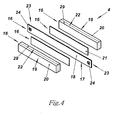
- Fig. 4 shows a variant of the friction rail 4, in which the elastic layers 22 are designed as parts 29 of the plate 20 of the friction layers 19.
- FIG. 2 shows a variant of the ultrasonic oscillator 2 of the drive 1 according to the invention.
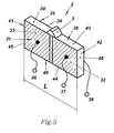
- the oscillator 2 is in the form of a piezoelectric plate 30 with two exciter electrodes 31, 32 on one of their large sides 33 and the collecting electrode 34 on the other large side 35. 34 have the outputs 36, 37, 38.
- the plate 30 is polarized perpendicular to the electrodes 31, 32 and 34.
- In the central part of one of the side surfaces 39 of the plate 30 is the friction element 3 of the oscillator 2.
- the other side surface 40 of the plate 30 is free.
- the plate 30 has the end faces 41 and 42.
- the sides 39, 40 and 41, 42 have the surfaces 43, 44 and 45, 46 on.
- an asymmetric ultrasonic standing wave is excited in the oscillator 2 whose wavelength ⁇ is equal to or a multiple of the length L of the plate 30 along the side surface 39 or 40 (see Fig. 5 ).
- the proposed invention also provides other constructional embodiments of the ultrasonic oscillators 2, which contain a plurality of exciter electrodes 31 and a plurality of exciter electrodes 32. These constructions of the oscillators 2 will not be considered further in the description.
- the layers 16 of the multilayer friction rail 4 are arranged parallel to the side surfaces 39 and 40 of the plate 30 of the oscillator 2.
- the positions 47, 48 in the Fig. 6 show the deformation of the plate 30 of the oscillator 2.
- the graphs show them with a time shift by a half oscillation period of the oscillator 2.
- the positions 49, 50, 51, 52 show the trajectories 53 of the points 54 of the surfaces 43, 44, 45, 46 the sides 39, 40, 41, 42 of the plate 30.
- the surfaces 43, 44 have minima (55, 56) of the vibration velocities.
- the surfaces 45, 46 have maxima (57, 58) of the vibration velocities.
- the graphs show the state at a time shift by a half oscillation period of the oscillator 2.
- the arrow 61 shows the moving direction of the dots 50 upon compression and elongation of the disk 30 of the oscillator 2.
- This force F o is formed.
- This force F o consists of the contact force generated by the elastic elements 5 and of the force generated by the ultrasonic oscillator 2.
- the inclination angle of the force F o to the friction layer 19 (20, 26) is ⁇ . This force can be decomposed into the normal force F n and the tangential force F t .
- the arrow 62 indicates the direction of movement of the friction rail 4.
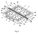
- Fig. 8 shows one of the mounting variants of the oscillator 2 in the holding device 6.
- the oscillator 2 by the two opposing (C-shaped) elastic support 63 is held.
- the outer parts 64 of the elastic supports 63 hold the oscillator 2 at its opposite end faces 41, 42 in its maxima of the vibration velocities 57, 58.
- the central parts 65 of the elastic supports 63 are fastened to the holding device 6 of the oscillator 2.
- the elastic supports 63 may be made of various types of elastic plastics filled with glass fibers or carbon threads. They can be cast together with the holding device 6 of the oscillator 2.
- the pressing elastic element 5 is designed as a leaf spring.
- Paragraph 66 in Fig. 9 schematically shows the graphs of the two deformation phases of one of the surfaces 45 or 46 of the end faces 41 or 42 of the plate 30 of the oscillator 2.
- numeral 67 of Fig. 9 shows one of the elastic support 63, which engages in one of the end faces 41 or 42 of the plate 30 of the oscillator 2.
- Position 68 shows the dependence of the cross-sectional area S of the elastic support 63 (dotted line) and the vibration velocity V of this cross-section (dashed dotted line) from the distance X of this cross-section to the central line 69 passing through the plate center 30 of the oscillator.
- Fig. 10 shows a second mounting variant of the oscillators 2 in the housing 6.
- the oscillators 2 are arranged in four elastic frame members 70.
- Each of the frame supports 70 is arranged parallel to the side surfaces 39, 40 of the oscillator 2.
- each support frame 70 is disposed on the side surface 39 or 40 of the oscillator 2 at its minimum of the oscillation speed 55 or 56.
- a second side 72 of the support frame is on the fixture 6 of the oscillator 2 attached.
- elastic pressing elements 5 are designed as a cylindrical spring.
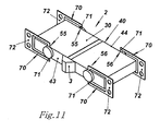
- Fig. 11 shows the oscillator 2 with attached to it support frame 70th
- the support frames 70 are made of thin metal bands or thin metal sheets by stamping, laser cutting or eroding.
- As the material for the support frames 70 heat-treated steels, beryllium bronze, titanium or other aluminum alloys may be used.
- the thickness of the support frame is selected to be approximately equal to 0.01 ⁇ .
- Paragraphs 73 and 74 of the Fig. 12 show variants of the attachment of the support frame 70 to the plate 30 of the oscillator 2.
- one side of the support 70 is glued to the surface 43 or 44 by means of the adhesive drop 75.
- bonding takes place by means of the transitional shell 76.
- Fig. 13 shows the deformation of the oscillator 2 with mounted on it support frame 70th
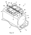
- Fig. 14 shows the proposed drive, in which the holding device 11 holds an optical lens group 77.
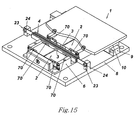
- Fig. 15 shows a variant of the proposed drive, in which the friction rail 4 is connected with its attachment points 24 with the base plate 8.
- the holding device 6 of the oscillator 2 is mounted on the movable holder 11.
- Fig. 16 shows a further mounting variant of the oscillator 2.
- the elastic elements 5 are designed as thin tension springs which are glued with glue 75 or soldered by means of a solder drop 75 on the electrodes 31, 32, 34 of the oscillator 2.
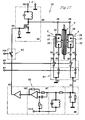
- Fig. 17 shows the electrical circuit of an exciter device 12, designed as a self-exciting generator with the excitation frequency ⁇ o, which is determined by the mechanical parameters of an active ultrasonic oscillator 78, wherein a second passive ultrasonic oscillator 79 is connected to the excitation device 12 as a passive element.
- This device consists of a power amplifier 80, a direction selector switch 81, a feedback circuit 82 and an off switch 83.
- the power amplifier 80 has a control input 84 and an amplifier output 85.
- the direction selector 81 has control inputs 86, 87, switching inputs 88, 89, 90, 91 and Outputs 92, 93 on.
- the feedback circuit 82 has a control input 94 and an output 95 and consists of an element 96 of the feedback circuit, a filter 97, a phase shifter 98 and an amplifier 99.
- the element of the feedback circuit may be designed as a resistor or as a capacitor or of these two connected in parallel Elements exist.
- the switch 83 has a control input 100.
- the power supply is provided by a power supply with the voltage E, which is connected to a feed input 101.
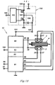
- Fig. 18 shows the electrical circuit of the excitation device 12, implemented as a self-exciting generator and additionally equipped with a regulated PWM converter 102 for DC voltage.
- the PWM converter 102 consists of a controlled PWM generator 103 with analog control input 104 and power amplifier 105 with a filter 106, an output 107 and a power supply input 108.
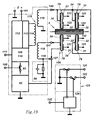
- Fig. 19 12 shows the electrical circuit of the excitation device 12, implemented as a self-exciting generator, including a balanced PWM controller 109, or as a balanced phase-shifting controller 110 with analog control input 111.
- the balanced PWM controller 109 or the balanced phase-shifting controller 110 are connected to inputs 112 of the power bridge amplifier connected, wherein a filter 113 and a first winding 114 of a transformer 115 form their load.
- a first secondary winding 116 of the transformer 115 is connected at one of its outputs 117 to the collecting electrode 34 of the active oscillator 78. Its second output 118 is connected to the element 96 of the feedback loop.
- a second secondary winding 119 of the transformer 115 is connected at its output 120 to the collecting electrode 34 of the passive oscillators 79.
- the excitation electrodes 31, 32 of the oscillators 78, 79 are connected to switching inputs 121, 122 of a direction selector 123, which consists of an inverter 124 with Umschalteingang 125.
- an additional electrode 126 or an additional piezo element can be used which is connected to the input 127 of the feedback circuit 82 - as in FIG Fig. 19 shown with dotted line - is connected.
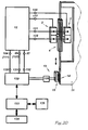
- Fig. 20 shows the electrical circuit of the proposed drive, which is equipped with a high-resolution measuring system 13 with the measuring ruler 14, the optical reading head 15 and an interpolator 128.
- this drive has a processor controller 129 for position or speed of the movable holder 11 with control inputs 130, 131, 132.
- the process controller 129 may be connected to a control computer 133, a keyboard 134 and a display 135.
- the points 54 of the surface 43 of the side surface 39 move on inclined trajectories 53, shown with numeral 43, Fig. 6 , Since the central parts of the surface 43 of the side surfaces 39 are at the maximum of the vibration velocities, the friction element 3 located on the plate 30 oscillates with maximum amplitude.
- the friction element 3 moves on an inclined track whose direction at the numbers 59 and 60 of the Fig. 7 indicated by the arrow 61.
- the friction element 3 presses on movement in the direction of the friction rail 4 (position 59) on the friction layer 19 (20, 26) with the force F o .
- This force is inclined at an angle ⁇ to the friction layer 19 (20, 26) and can therefore be decomposed into a normal force component F n and a tangential component F t .
- the normal force component F n pushes the friction element 3 against the friction layer 19 (20, 26), whereby a toothing between the friction element 3 and the friction layer 19 (20, 26) takes place.
- the tangential component F t transmits to the friction rail 4 a longitudinal or rotational movement.
- the friction rail 4 moves the movable holding device 11 in motion. The exact direction of movement of the holding device 11 is determined by the carriage 10, which moves on the mounted on the base plate of the drive 1 guide rail 9.
- this layer - based on the unstressed state (free mobility) - something bent.
- the amount of deflection depends on the elasticity of the friction layers 19 (20, 26) and the elastic layers 22 (28) as well as the viscosity of the viscous layers 21 (27). In a first approximation, the deflection of the friction layer 19 (20, 26) is 1... 4 microns.
- the layers 19 (20, 26), 22 (28) and 17 (18, 25) have a substantially smaller thickness than the wavelength ⁇ , no ultrasonic wave is propagated in any of the layers along the thickness of the layer.
- the vibration amplitude of the friction layer 19 (20, 26) is much smaller than the vibration amplitude of the friction element 3. Since the friction layer 4 consists of several viscous layers (21, 27), each subsequent elastic layer 22 (28) has a substantial one lower vibration amplitude than the previous layer. Therefore, even with 2... 3 elastic layers 22 (28), no ultrasonic waves occur in the central layer 17 (18, 25). This makes it possible to completely isolate the attachment points of the plate 18 (25) from ultrasonic vibrations in these locations. Therefore, the friction rail 4 does not generate ultrasonic vibrations in the movable holder 11.
- a certain effect of suppression of the ultrasonic wave also occurs when the elastic layers 22 as parts 29 of the plates 20 of the friction layers 19, as shown in FIG Fig. 4 shown are executed.
- Fig. 1 shown variant of the proposed high-precision ultrasonic drive, a small penetration of the ultrasonic vibrations from the oscillator 2 to the movable holding device 11 via the wall 7 of the holding device 6 of the oscillator 2 done. Therefore, the proposed invention provides some variants for complete acoustic isolation of the oscillator 2.
- each of the ultrasonic oscillators 2 in opposing elastic supports 63 as in Fig. 8 and 9 shown, mounted.
- the carrier of the oscillator 2 is held securely, since they engage on the ends of its end faces 41, 42 in the oscillator 2.
- the sides 41 and 42 swing in with the numbers 47, 48, 51, 52 in Fig. 6 and with the number 66 in Fig. 9 shown form.
- the outer parts 64 of the elastic supports 63 engage in the end faces 41, 42 in the maxima 57, 58 of the vibration velocities of the surfaces 41, 42. Therefore, the outer parts 64 of the carriers 63 vibrate at maximum vibration speed.
- the elastic straps 63 are designed so that the cross-sectional area S of each of the straps 63 increases from the outer portion 64 of the wearer towards the central portion 65 of the wearer, as indicated by the dotted line with numeral 68 in FIG Fig. 9 is pictured.
- the increase in the cross-sectional area S results in a quadratic reduction in the vibration velocity V (running cross-section) of the beam 63.
- the vibration velocity V of the current cross section of the beam 63 decreases linearly due to the reduction in the distance from the running cross-section of the beam
- the speed of oscillation of the running cross-section of the carrier 63 is reduced as shown in position 68, to the central line 69 passing through the center of the plate 30.
- Fig. 9 represented by the dash-dotted line.
- the vibration velocity V of the central part 65 of the carrier 63 is practically zero. This means that the carriers 63 do not transmit ultrasonic vibrations to the holding device 6.
- each of the oscillators 2 is mounted in two or four frame rails 70, as shown in FIG Fig. 10 . 11 . 12 shown.
- the first side 71 of each of the support frames 70 is mounted at a minimum of the oscillation speeds 55, 56 of the surfaces 43, 44.
- the points 54 of these surfaces vibrate in the minima of the vibration velocities 55 perpendicular to the surface of the carrier 70 (see Fig. 6 , Numerals 49, 50).
- These vibrations generate a low amplitude bending wave in the carrier 70 (see Fig. 13 ).
- the second side 72 of the carrier 70 is fixed in the holding device 6, which has a larger cross-sectional area than the cross-sectional area of the carrier 70. Therefore, the bending shaft is reflected by the holding device 6 and does not penetrate into it. This means that the carrier frame 70 isolates the oscillator 2 from the holding device 6 of the oscillator 2.
- the support frames 70 have a high strength in the longitudinal direction. Therefore, they allow high rigidity of the drive in the longitudinal direction. As a result, a high positioning accuracy is possible even when moving heavy moving parts as well as at high speeds of movement of the movable holding device.
- the embodiment of the carrier 70 as a frame allows a high stability of the oscillator 2 in its direction of movement. This also increases the positioning accuracy.
- the movable holding device 11 holds the optical lens group 77.
- the design of the drive makes it possible to completely isolate the holding device 11 from the penetration of ultrasonic vibrations in it.
- the holding device 6 of the oscillators 2 is fixed in the movable holding device 11. This construction of the drive makes it possible to completely protect the movable holding device 11 from the penetration of ultrasonic vibrations.
- each of the elastic elements 5 (designed as coil springs) in the side surfaces 39, 40 of the plate 30 of the oscillator 2 is fixed.
- the elastic elements 5 firmly hold the two oscillators 2 together by pressing the friction elements 3 against the friction rail 4. Since the elastic members 5 have no contact with the holding device 6 of the oscillator 2, it is possible to prevent the movable holder 11 from penetrating ultrasonic vibrations.
- the synchronous function of the two opposed oscillators 2 is very important. This means that the friction elements 3 of the oscillator 2 must synchronously approach each other and move away from each other. Only in this case does the drive develop its maximum speed and maximum traction.
- the frequency of the exciter voltage must correspond to the operating frequency ⁇ o of the oscillator 2.
- Fig. 17 shows the electrical circuit of the excitation device 12 through which the synchronous work of the two or more oppositely arranged oscillators 2 ensured.
- the exciter device 12 is a self-exciting generator whose frequency is determined by the mechanical. Parameter of the active ultrasonic oscillator 78 (2) is predetermined.
- This exciter device works as follows:
- the transistor of the power amplifier 80 When the switch 83 is turned on, the transistor of the power amplifier 80 is opened. The electrode 34 of the oscillator 78 is connected to the electrode 31 (or 32). As a result, a pulse of static capacitance discharge current flows through the feedback loop element 96 of the oscillator 2. At the input 94 of the element of the feedback loop, a pulse is formed in the feedback loop. This pulse passes through the feedback 82, is inverted and passes from the output 95 via the switch 83 to the input 84 of the amplifier 80. The transistor of the power amplifier 80 closes. This results in the charging of the static capacitance of the oscillator 2. At the element 96 of the feedback circuit, a second voltage pulse is formed, which closes the feedback circuit through the transistor of the power amplifier 80. The result is a vibration process whose oscillation frequency is determined by the phase shift in the entire closed feedback loop.
- the circuit is balanced so that the working frequency where the total phase shift is zero degrees. This is achieved by adjusting the corresponding phase shift of the phase shifter 98. With a phase shift equal to zero, the excitation frequency is determined by the mechanical parameters of the oscillator 78.
- the oscillator Since the current of the oscillator 79 does not flow through the element 96 of the feedback loop, the oscillator is passive and has no influence on the frequency of the excitation device. Since similar oscillators are used with the same dimensions in the proposed drive, the excitation frequency ⁇ o at the same time represents the operating frequency for the oscillator 79. Therefore, the friction elements of the oscillators 78 and 79 oscillate synchronously.
- the application of voltage pulses to the control input 100 of the switch 83 allows the pulse-controlled movement of the drive 1.
- the application of voltage pulses to the inputs 76, 87 of the direction selector switch 81 allows the pulse-controlled change of the direction of movement of the drive 1.
- the excitation device 12 comprises a DC voltage PWM converter 102, as in FIG Fig. 18 shown.
- the drive works as follows:
- the width of the PWM pulses provided by the PWM generator 103 changes. These pulses reach the input of the power amplifier 105, are amplified and smoothed by the filter 106. As a result, an analogous voltage that forms at the output 107 of the power amplifier 80 of the excitation device 12 is formed at the output 107.
- the voltage change at the feed input 101 results in a proportional change in the excitation level of the ultrasonic oscillators 2 and consequently in the proportional change of the moving speed of the friction rail 4 and the movable holding device 11.
- the Fig. 19 shows the electrical circuit of another excitation device 12. This variant of the exciter device operates as follows:
- Balanced PWM controller 109 provides two PWM signals whose angular position remains constant with respect to the feedback pulses. These two PWM signals reach the inputs of the power bridge amplifier 112 and control the function of this amplifier.
- the symmetrical phase shifting controller 110 provides two balanced phase shifting square wave signals whose phase shift symmetry remains constant with respect to the feedback pulses. These two signals go to the inputs of the power amplifier 112 and control the function of this amplifier.
- a bipolar PWM signal is formed in the diagonal of the bridge amplifier 112. This signal is applied to the transformer 115 via the filter 113. At the secondary windings 116 (outputs 117, 118) and 119 (output 120) of the transformer 115 forms a sinusoidal voltage. The phase shift of this voltage remains, based on the signal of the feedback when changing the control signal voltage at the analog input 111, constant. It only changes the amplitude of this voltage.
- the PWM controller 109 and the symmetrical phase shift controller 110 do not generate a delay in the control signal. This makes it possible to control the drive 1 in an analogous manner without delay.
- each of the variants of the excitation device can be used as an element of the feedback, an additional electrode or an additional arranged on the oscillator 2 piezoelectric element 126, as Fig. 19 is shown.
- inverter 124 in the direction selector 123 ( Fig. 19 ) makes it possible to switch with the aid of a Umschalteingangs 125, the direction of movement of the drive 1.
- the proposed drive can be equipped with a high-resolution measuring system 13 and a position and speed processor controller 129 of the movable holding device 11 (FIG. Fig. 20 ).
- the coordinates of the holding device 11 are determined by means of the reading head 15 with the interpolator 128 and the measuring ruler 14 of the measuring system 13.
- the coordinate values reach the processor controller 129, which provides with its outputs 130, 131, 132 the control signal for the speed of movement and the signal or the signals for switching the direction of movement.
- These signals are applied to the inputs 104 (11), 86 (125), 87 of the excitation device 12 and control the movement or the stop of the movable holder 11.
- the computer 133 with the keyboard 134 and the display 135 serves to specify the position or Movement parameters of the movable holding device 11 and the specification of the control parameters for the processor controller 129th
- Modern optical measuring systems allow the measurement of the position of the movable holding device 11 with an accuracy of +/- 2 nanometers.
- the absence of ultrasonic vibrations in the movable holder 11 and the base plate 8 of the proposed drive makes it possible to position the movable holder 11 with the same accuracy.
- Such a drive ensures a smooth running (uniformity) of the movable holding device 11 even at low speeds of movement, so that at a speed of 1 micrometer / second, the drive enables a uniformity of the speed of better than 1%.
- the proposed drive makes it possible to precisely focus the optical systems, so that it is possible to follow the accuracy of the focus during the time of movement of the movable holding device 11.
Landscapes
- General Electrical Machinery Utilizing Piezoelectricity, Electrostriction Or Magnetostriction (AREA)
- Surgical Instruments (AREA)
- Ultra Sonic Daignosis Equipment (AREA)
Claims (15)
- Entraînement à ultrasons (1) comprenant au moins deux oscillateurs à ultrasons (2) agencés à l'opposé l'un de l'autre, qui comprennent des plaques piézo-électriques avec des éléments de friction (3) agencés sur celles-ci, un rail à friction (4) avec deux couches de friction sur lui-même, un dispositif de maintien mobile (6), et une plaque de base (8) pour l'entraînement et un dispositif excitateur (12) des oscillateurs à ultrasons,
caractérisé en ce que
le rail à friction est réalisé sous la forme d'un barreau multicouche ou d'une bague multicouche présentant respectivement un nombre impair de couches (16) présentant les éléments de friction et agencées parallèlement aux surfaces latérales (39) des plaques piézo-électriques, dans lequel une couche centrale (17) comprend une plaque ou un disque porteur et deux couches extérieures (19), qui forment des couches de friction, et entre la couche centrale et les couches extérieures sont agencées des couches visqueuses (21) et des couches élastiques (22), et la plaque ou le disque porteur comporte des points de fixation (24) au moyen desquels le rail à friction est agencé sur le dispositif de maintien mobile ou sur la plaque de base. - Entraînement à ultrasons selon la revendication 1,
caractérisé en ce que la couche centrale (17) présente une épaisseur plus faible par rapport aux deux autres dimensions et/ou présente une élasticité prédéterminée, en particulier une élasticité en flexion prédéterminée. - Entraînement à ultrasons selon la revendication 1 et 2,
caractérisé en ce que plusieurs couches visqueuses (21) et plusieurs couches élastiques (22) sont agencées respectivement en alternance entre la couche centrale (17) et les deux couches extérieures (19). - Entraînement à ultrasons selon l'une des revendications précédentes,
caractérisé en ce que l'une au moins des couches élastiques (22) est réalisée en tant que partie d'une couche de friction. - Entraînement à ultrasons selon l'une des revendications précédentes,
caractérisé en ce que la couche centrale (17) est en acier ou en bronze au béryllium ou en matière plastique. - Entraînement à ultrasons selon l'une des revendications précédentes,
caractérisé en ce que les couches de friction sont en céramique à base d'oxyde, en céramique à base de métal ou en acier. - Entraînement à ultrasons selon l'une des revendications précédentes,
caractérisé en ce que les couches visqueuses (21) sont en caoutchouc, en matériau polymère ou en papier, en particulier à effet collant. - Entraînement à ultrasons selon l'une des revendications précédentes,
caractérisé en ce que les couches élastiques (22) sont en acier, en titane, en cuivre, en aluminium ou en céramique à base d'oxyde. - Entraînement à ultrasons selon l'une des revendications précédentes,
caractérisé en ce que chacun des oscillateurs à ultrasons (2) est agencé dans des supports élastiques opposés (63), les parties extérieures du support élastique tiennent l'oscillateur à ultrasons respectifs au niveau de ses faces frontales opposées à ses maxima des vitesses d'oscillation, et des parties centrales du support élastique sont reliées au dispositif de maintien (6) de l'oscillateur. - Entraînement à ultrasons selon la revendication 9,
caractérisé en ce que les supports élastiques (63) sont réalisés de telle façon que la surface de section transversale (S) de chaque support augmente de la région extérieure vers la région intérieure du support. - Entraînement à ultrasons selon l'une des revendications précédentes,
caractérisé en ce que chacun des oscillateurs à ultrasons (2) est fixé dans deux ou quatre cadres porteurs élastiques (70), qui sont agencés parallèlement aux faces latérales de l'oscillateur à ultrasons respectif, et chacun des cadres porteurs est tenu sur la face latérale respective au minimum de la vitesse d'oscillation de l'oscillateur à ultrasons et est relié au dispositif de maintien de l'oscillateur. - Entraînement à ultrasons selon l'une des revendications précédentes,
caractérisé en ce que le dispositif excitateur (12) des oscillateurs à ultrasons (2) est réalisé comme un générateur à auto-excitation, dont la fréquence d'excitation est imposée par les paramètres mécaniques de l'un des oscillateurs à ultrasons actifs, et les autres oscillateurs à ultrasons sont reliés au dispositif excitateur comme des éléments passifs. - Entraînement à ultrasons selon la revendication 12,
caractérisé en ce que le dispositif excitateur (12) est équipé d'un convertisseur à modulation de largeur d'impulsion (102) régulé pour une tension continue. - Entraînement à ultrasons selon la revendication 12 ou 13,
caractérisé en ce que le générateur à auto-excitation comprend un contrôleur symétrique à modulation de largeur d'impulsion (109) ou un contrôleur symétrique (110) à décalage de phase. - Entraînement à ultrasons selon l'une des revendications précédentes, caractérisé en ce qu'il est équipé d'un système de mesure (13) à haute résolution et d'un moyen de régulation (129) pour la position et/ou pour la vitesse du dispositif de maintien mobile.
Applications Claiming Priority (3)
| Application Number | Priority Date | Filing Date | Title |
|---|---|---|---|
| DE102006055923 | 2006-11-27 | ||
| DE102007008252A DE102007008252A1 (de) | 2006-11-27 | 2007-02-20 | Ultaschallantrieb |
| PCT/EP2007/061817 WO2008064974A1 (fr) | 2006-11-27 | 2007-11-02 | Entraînement à ultrasons |
Publications (2)
| Publication Number | Publication Date |
|---|---|
| EP2095441A1 EP2095441A1 (fr) | 2009-09-02 |
| EP2095441B1 true EP2095441B1 (fr) | 2010-08-11 |
Family
ID=39156537
Family Applications (1)
| Application Number | Title | Priority Date | Filing Date |
|---|---|---|---|
| EP07847102A Active EP2095441B1 (fr) | 2006-11-27 | 2007-11-02 | Entraînement à ultrasons |
Country Status (4)
| Country | Link |
|---|---|
| EP (1) | EP2095441B1 (fr) |
| AT (1) | ATE477593T1 (fr) |
| DE (2) | DE102007008252A1 (fr) |
| WO (1) | WO2008064974A1 (fr) |
Cited By (1)
| Publication number | Priority date | Publication date | Assignee | Title |
|---|---|---|---|---|
| DE102015004208A1 (de) | 2015-03-31 | 2016-10-06 | Physik Instrumente (Pi) Gmbh & Co. Kg | Verfahren zur Steuerung eines Ultraschallmotors und entsprechende Steueranordnung |
Families Citing this family (3)
| Publication number | Priority date | Publication date | Assignee | Title |
|---|---|---|---|---|
| DE102008016684B4 (de) | 2008-04-01 | 2015-10-08 | Minebea Co., Ltd. | Elektromechanischer Motor |
| DE102011087801B4 (de) | 2011-02-22 | 2013-04-25 | Physik Instrumente (Pi) Gmbh & Co. Kg | Ultraschallmotor |
| CN115589519B (zh) * | 2022-10-19 | 2024-12-06 | Oppo广东移动通信有限公司 | 压电致动器、摄像头模组及电子设备 |
Family Cites Families (4)
| Publication number | Priority date | Publication date | Assignee | Title |
|---|---|---|---|---|
| JPS60174074A (ja) * | 1984-01-30 | 1985-09-07 | Canon Inc | 振動波モ−タ |
| JPS63316676A (ja) * | 1987-06-19 | 1988-12-23 | Mitsubishi Electric Corp | 圧電リニアモ−タ |
| JPH11299269A (ja) * | 1998-04-14 | 1999-10-29 | Koganei Corp | リニアアクチュエータ |
| DE19938954A1 (de) * | 1999-08-17 | 2001-03-08 | Pi Ceramic Gmbh Keramische Tec | Piezoelektrischer Antrieb, insbesondere zur Erzeugung von Rotations- oder Translationsbewegungen, die stetig oder schrittweise erfolgen können |
-
2007
- 2007-02-20 DE DE102007008252A patent/DE102007008252A1/de not_active Ceased
- 2007-11-02 DE DE502007004746T patent/DE502007004746D1/de active Active
- 2007-11-02 WO PCT/EP2007/061817 patent/WO2008064974A1/fr not_active Ceased
- 2007-11-02 AT AT07847102T patent/ATE477593T1/de active
- 2007-11-02 EP EP07847102A patent/EP2095441B1/fr active Active
Cited By (3)
| Publication number | Priority date | Publication date | Assignee | Title |
|---|---|---|---|---|
| DE102015004208A1 (de) | 2015-03-31 | 2016-10-06 | Physik Instrumente (Pi) Gmbh & Co. Kg | Verfahren zur Steuerung eines Ultraschallmotors und entsprechende Steueranordnung |
| DE102015004208B4 (de) * | 2015-03-31 | 2016-12-22 | Physik Instrumente (Pi) Gmbh & Co. Kg | Verfahren zur Steuerung eines Ultraschallmotors und entsprechende Steueranordnung |
| US10312831B2 (en) | 2015-03-31 | 2019-06-04 | Physik Instrumente (Pi) Gmbh & Co. Kg | Method for controlling an ultrasound motor and corresponding control arrangement |
Also Published As
| Publication number | Publication date |
|---|---|
| WO2008064974A1 (fr) | 2008-06-05 |
| DE102007008252A1 (de) | 2008-05-29 |
| EP2095441A1 (fr) | 2009-09-02 |
| DE502007004746D1 (de) | 2010-09-23 |
| ATE477593T1 (de) | 2010-08-15 |
Similar Documents
| Publication | Publication Date | Title |
|---|---|---|
| DE19945042C2 (de) | Piezoelektrischer Antrieb, insbesondere piezoelektrischer Motor sowie Schaltungsanordnung zum Betreiben eines piezoelektrischen Motors | |
| EP1656705B1 (fr) | Moteur a ultrasons lineaire | |
| DE3587940T2 (de) | Piezoelektrischer Motor. | |
| EP1761999B1 (fr) | Unite d'entrainement | |
| EP2731256B1 (fr) | Actionneur à ultrasons pour un moteur linéaire à ultrasons et moteur linéaire à ultrasons doté d'un actionneur à ultrasons | |
| DE10154526B4 (de) | Piezoelektrisches Stellelement | |
| DE69734132T2 (de) | Trägheits-Positionierer | |
| DE19938954A1 (de) | Piezoelektrischer Antrieb, insbesondere zur Erzeugung von Rotations- oder Translationsbewegungen, die stetig oder schrittweise erfolgen können | |
| EP2497129B1 (fr) | Actionneur | |
| EP2095441B1 (fr) | Entraînement à ultrasons | |
| EP2258004B1 (fr) | Moteur à ultrasons de haute précision | |
| EP1812975A1 (fr) | Moteur a ultrasons lineaire | |
| EP3469703B1 (fr) | Moteur à ultrasons | |
| DE69709739T2 (de) | Piezoelektrischer motor mit unabhängigen statormodulen | |
| EP2208243B1 (fr) | Mécanisme d'entraînement linéaire ultrasonore comprenant un oscillateur en forme de cylindre creux | |
| EP2678934B1 (fr) | Moteur à ultrasons | |
| EP2608286B1 (fr) | Actionneur à ultrasons | |
| DE102014111168A1 (de) | Schwingförderer zur zweidimensionalen Bewegung von Objekten sowie Verfahren zum Betrieb des Schwingförderers | |
| EP2422379A1 (fr) | Moteur à ultrasons | |
| DE4435882C2 (de) | Ultraschallmotor | |
| DE3851781T2 (de) | Wanderwellenmotor. | |
| WO2010083813A1 (fr) | Palier à air généré par ultrasons | |
| DE19811025B4 (de) | Mechanischer Oszillator und Verfahren zum Erzeugen einer mechanischen Schwingung | |
| WO2023227171A1 (fr) | Entraînement à inertie piézoélectrique | |
| EP0413111B1 (fr) | Moteur à onde progressive ultra-sonore à deux ou plusieurs plots |
Legal Events
| Date | Code | Title | Description |
|---|---|---|---|
| PUAI | Public reference made under article 153(3) epc to a published international application that has entered the european phase |
Free format text: ORIGINAL CODE: 0009012 |
|
| 17P | Request for examination filed |
Effective date: 20081113 |
|
| AK | Designated contracting states |
Kind code of ref document: A1 Designated state(s): AT BE BG CH CY CZ DE DK EE ES FI FR GB GR HU IE IS IT LI LT LU LV MC MT NL PL PT RO SE SI SK TR |
|
| 17Q | First examination report despatched |
Effective date: 20090925 |
|
| GRAP | Despatch of communication of intention to grant a patent |
Free format text: ORIGINAL CODE: EPIDOSNIGR1 |
|
| DAX | Request for extension of the european patent (deleted) | ||
| GRAS | Grant fee paid |
Free format text: ORIGINAL CODE: EPIDOSNIGR3 |
|
| GRAA | (expected) grant |
Free format text: ORIGINAL CODE: 0009210 |
|
| AK | Designated contracting states |
Kind code of ref document: B1 Designated state(s): AT BE BG CH CY CZ DE DK EE ES FI FR GB GR HU IE IS IT LI LT LU LV MC MT NL PL PT RO SE SI SK TR |
|
| REG | Reference to a national code |
Ref country code: GB Ref legal event code: FG4D Free format text: NOT ENGLISH |
|
| REG | Reference to a national code |
Ref country code: CH Ref legal event code: EP |
|
| REG | Reference to a national code |
Ref country code: IE Ref legal event code: FG4D Free format text: LANGUAGE OF EP DOCUMENT: GERMAN |
|
| REF | Corresponds to: |
Ref document number: 502007004746 Country of ref document: DE Date of ref document: 20100923 Kind code of ref document: P |
|
| REG | Reference to a national code |
Ref country code: NL Ref legal event code: VDEP Effective date: 20100811 |
|
| LTIE | Lt: invalidation of european patent or patent extension |
Effective date: 20100811 |
|
| PG25 | Lapsed in a contracting state [announced via postgrant information from national office to epo] |
Ref country code: NL Free format text: LAPSE BECAUSE OF FAILURE TO SUBMIT A TRANSLATION OF THE DESCRIPTION OR TO PAY THE FEE WITHIN THE PRESCRIBED TIME-LIMIT Effective date: 20100811 Ref country code: FI Free format text: LAPSE BECAUSE OF FAILURE TO SUBMIT A TRANSLATION OF THE DESCRIPTION OR TO PAY THE FEE WITHIN THE PRESCRIBED TIME-LIMIT Effective date: 20100811 Ref country code: LT Free format text: LAPSE BECAUSE OF FAILURE TO SUBMIT A TRANSLATION OF THE DESCRIPTION OR TO PAY THE FEE WITHIN THE PRESCRIBED TIME-LIMIT Effective date: 20100811 |
|
| PG25 | Lapsed in a contracting state [announced via postgrant information from national office to epo] |
Ref country code: PT Free format text: LAPSE BECAUSE OF FAILURE TO SUBMIT A TRANSLATION OF THE DESCRIPTION OR TO PAY THE FEE WITHIN THE PRESCRIBED TIME-LIMIT Effective date: 20101213 Ref country code: PL Free format text: LAPSE BECAUSE OF FAILURE TO SUBMIT A TRANSLATION OF THE DESCRIPTION OR TO PAY THE FEE WITHIN THE PRESCRIBED TIME-LIMIT Effective date: 20100811 Ref country code: BG Free format text: LAPSE BECAUSE OF FAILURE TO SUBMIT A TRANSLATION OF THE DESCRIPTION OR TO PAY THE FEE WITHIN THE PRESCRIBED TIME-LIMIT Effective date: 20101111 Ref country code: SI Free format text: LAPSE BECAUSE OF FAILURE TO SUBMIT A TRANSLATION OF THE DESCRIPTION OR TO PAY THE FEE WITHIN THE PRESCRIBED TIME-LIMIT Effective date: 20100811 Ref country code: IS Free format text: LAPSE BECAUSE OF FAILURE TO SUBMIT A TRANSLATION OF THE DESCRIPTION OR TO PAY THE FEE WITHIN THE PRESCRIBED TIME-LIMIT Effective date: 20101211 Ref country code: CY Free format text: LAPSE BECAUSE OF FAILURE TO SUBMIT A TRANSLATION OF THE DESCRIPTION OR TO PAY THE FEE WITHIN THE PRESCRIBED TIME-LIMIT Effective date: 20100811 |
|
| REG | Reference to a national code |
Ref country code: IE Ref legal event code: FD4D |
|
| PG25 | Lapsed in a contracting state [announced via postgrant information from national office to epo] |
Ref country code: GR Free format text: LAPSE BECAUSE OF FAILURE TO SUBMIT A TRANSLATION OF THE DESCRIPTION OR TO PAY THE FEE WITHIN THE PRESCRIBED TIME-LIMIT Effective date: 20101112 Ref country code: SE Free format text: LAPSE BECAUSE OF FAILURE TO SUBMIT A TRANSLATION OF THE DESCRIPTION OR TO PAY THE FEE WITHIN THE PRESCRIBED TIME-LIMIT Effective date: 20100811 Ref country code: LV Free format text: LAPSE BECAUSE OF FAILURE TO SUBMIT A TRANSLATION OF THE DESCRIPTION OR TO PAY THE FEE WITHIN THE PRESCRIBED TIME-LIMIT Effective date: 20100811 |
|
| PG25 | Lapsed in a contracting state [announced via postgrant information from national office to epo] |
Ref country code: DK Free format text: LAPSE BECAUSE OF FAILURE TO SUBMIT A TRANSLATION OF THE DESCRIPTION OR TO PAY THE FEE WITHIN THE PRESCRIBED TIME-LIMIT Effective date: 20100811 Ref country code: IE Free format text: LAPSE BECAUSE OF FAILURE TO SUBMIT A TRANSLATION OF THE DESCRIPTION OR TO PAY THE FEE WITHIN THE PRESCRIBED TIME-LIMIT Effective date: 20100811 |
|
| BERE | Be: lapsed |
Owner name: PHYSIK INSTRUMENTE (PI) G.M.B.H. & CO. KG Effective date: 20101130 |
|
| PG25 | Lapsed in a contracting state [announced via postgrant information from national office to epo] |
Ref country code: SK Free format text: LAPSE BECAUSE OF FAILURE TO SUBMIT A TRANSLATION OF THE DESCRIPTION OR TO PAY THE FEE WITHIN THE PRESCRIBED TIME-LIMIT Effective date: 20100811 Ref country code: RO Free format text: LAPSE BECAUSE OF FAILURE TO SUBMIT A TRANSLATION OF THE DESCRIPTION OR TO PAY THE FEE WITHIN THE PRESCRIBED TIME-LIMIT Effective date: 20100811 Ref country code: IT Free format text: LAPSE BECAUSE OF FAILURE TO SUBMIT A TRANSLATION OF THE DESCRIPTION OR TO PAY THE FEE WITHIN THE PRESCRIBED TIME-LIMIT Effective date: 20100811 Ref country code: EE Free format text: LAPSE BECAUSE OF FAILURE TO SUBMIT A TRANSLATION OF THE DESCRIPTION OR TO PAY THE FEE WITHIN THE PRESCRIBED TIME-LIMIT Effective date: 20100811 Ref country code: CZ Free format text: LAPSE BECAUSE OF FAILURE TO SUBMIT A TRANSLATION OF THE DESCRIPTION OR TO PAY THE FEE WITHIN THE PRESCRIBED TIME-LIMIT Effective date: 20100811 |
|
| PLBE | No opposition filed within time limit |
Free format text: ORIGINAL CODE: 0009261 |
|
| STAA | Information on the status of an ep patent application or granted ep patent |
Free format text: STATUS: NO OPPOSITION FILED WITHIN TIME LIMIT |
|
| PG25 | Lapsed in a contracting state [announced via postgrant information from national office to epo] |
Ref country code: MC Free format text: LAPSE BECAUSE OF NON-PAYMENT OF DUE FEES Effective date: 20101130 Ref country code: ES Free format text: LAPSE BECAUSE OF FAILURE TO SUBMIT A TRANSLATION OF THE DESCRIPTION OR TO PAY THE FEE WITHIN THE PRESCRIBED TIME-LIMIT Effective date: 20101122 |
|
| 26N | No opposition filed |
Effective date: 20110512 |
|
| PG25 | Lapsed in a contracting state [announced via postgrant information from national office to epo] |
Ref country code: BE Free format text: LAPSE BECAUSE OF NON-PAYMENT OF DUE FEES Effective date: 20101130 |
|
| REG | Reference to a national code |
Ref country code: DE Ref legal event code: R097 Ref document number: 502007004746 Country of ref document: DE Effective date: 20110512 |
|
| PG25 | Lapsed in a contracting state [announced via postgrant information from national office to epo] |
Ref country code: MT Free format text: LAPSE BECAUSE OF FAILURE TO SUBMIT A TRANSLATION OF THE DESCRIPTION OR TO PAY THE FEE WITHIN THE PRESCRIBED TIME-LIMIT Effective date: 20100811 |
|
| REG | Reference to a national code |
Ref country code: CH Ref legal event code: PL |
|
| PG25 | Lapsed in a contracting state [announced via postgrant information from national office to epo] |
Ref country code: LI Free format text: LAPSE BECAUSE OF NON-PAYMENT OF DUE FEES Effective date: 20111130 Ref country code: CH Free format text: LAPSE BECAUSE OF NON-PAYMENT OF DUE FEES Effective date: 20111130 |
|
| PG25 | Lapsed in a contracting state [announced via postgrant information from national office to epo] |
Ref country code: LU Free format text: LAPSE BECAUSE OF NON-PAYMENT OF DUE FEES Effective date: 20101102 Ref country code: HU Free format text: LAPSE BECAUSE OF FAILURE TO SUBMIT A TRANSLATION OF THE DESCRIPTION OR TO PAY THE FEE WITHIN THE PRESCRIBED TIME-LIMIT Effective date: 20110212 |
|
| PG25 | Lapsed in a contracting state [announced via postgrant information from national office to epo] |
Ref country code: TR Free format text: LAPSE BECAUSE OF FAILURE TO SUBMIT A TRANSLATION OF THE DESCRIPTION OR TO PAY THE FEE WITHIN THE PRESCRIBED TIME-LIMIT Effective date: 20100811 |
|
| REG | Reference to a national code |
Ref country code: AT Ref legal event code: MM01 Ref document number: 477593 Country of ref document: AT Kind code of ref document: T Effective date: 20121130 |
|
| PG25 | Lapsed in a contracting state [announced via postgrant information from national office to epo] |
Ref country code: AT Free format text: LAPSE BECAUSE OF NON-PAYMENT OF DUE FEES Effective date: 20121130 |
|
| REG | Reference to a national code |
Ref country code: FR Ref legal event code: PLFP Year of fee payment: 9 |
|
| REG | Reference to a national code |
Ref country code: FR Ref legal event code: PLFP Year of fee payment: 10 |
|
| REG | Reference to a national code |
Ref country code: FR Ref legal event code: PLFP Year of fee payment: 11 |
|
| REG | Reference to a national code |
Ref country code: DE Ref legal event code: R079 Ref document number: 502007004746 Country of ref document: DE Free format text: PREVIOUS MAIN CLASS: H01L0041090000 Ipc: H10N0030200000 |
|
| P01 | Opt-out of the competence of the unified patent court (upc) registered |
Effective date: 20230602 |
|
| PGFP | Annual fee paid to national office [announced via postgrant information from national office to epo] |
Ref country code: DE Payment date: 20241119 Year of fee payment: 18 |
|
| PGFP | Annual fee paid to national office [announced via postgrant information from national office to epo] |
Ref country code: GB Payment date: 20241121 Year of fee payment: 18 |
|
| REG | Reference to a national code |
Ref country code: DE Ref legal event code: R081 Ref document number: 502007004746 Country of ref document: DE Owner name: PHYSIK INSTRUMENTE (PI) SE & CO KG, DE Free format text: FORMER OWNER: PHYSIK INSTRUMENTE (PI) GMBH & CO. KG, 76228 KARLSRUHE, DE |
|
| PGFP | Annual fee paid to national office [announced via postgrant information from national office to epo] |
Ref country code: FR Payment date: 20241122 Year of fee payment: 18 |