EP2095559B1 - Space division multiple access channelization in wireless communication systems - Google Patents
Space division multiple access channelization in wireless communication systems Download PDFInfo
- Publication number
- EP2095559B1 EP2095559B1 EP07853926.9A EP07853926A EP2095559B1 EP 2095559 B1 EP2095559 B1 EP 2095559B1 EP 07853926 A EP07853926 A EP 07853926A EP 2095559 B1 EP2095559 B1 EP 2095559B1
- Authority
- EP
- European Patent Office
- Prior art keywords
- different
- terminals
- resources
- sub
- tree
- Prior art date
- Legal status (The legal status is an assumption and is not a legal conclusion. Google has not performed a legal analysis and makes no representation as to the accuracy of the status listed.)
- Active
Links
Images





Classifications
-
- H—ELECTRICITY
- H04—ELECTRIC COMMUNICATION TECHNIQUE
- H04W—WIRELESS COMMUNICATION NETWORKS
- H04W72/00—Local resource management
- H04W72/12—Wireless traffic scheduling
- H04W72/1263—Mapping of traffic onto schedule, e.g. scheduled allocation or multiplexing of flows
- H04W72/1273—Mapping of traffic onto schedule, e.g. scheduled allocation or multiplexing of flows of downlink data flows
-
- H—ELECTRICITY
- H04—ELECTRIC COMMUNICATION TECHNIQUE
- H04B—TRANSMISSION
- H04B7/00—Radio transmission systems, i.e. using radiation field
- H04B7/02—Diversity systems; Multi-antenna system, i.e. transmission or reception using multiple antennas
- H04B7/04—Diversity systems; Multi-antenna system, i.e. transmission or reception using multiple antennas using two or more spaced independent antennas
- H04B7/06—Diversity systems; Multi-antenna system, i.e. transmission or reception using multiple antennas using two or more spaced independent antennas at the transmitting station
- H04B7/0697—Diversity systems; Multi-antenna system, i.e. transmission or reception using multiple antennas using two or more spaced independent antennas at the transmitting station using spatial multiplexing
-
- H—ELECTRICITY
- H04—ELECTRIC COMMUNICATION TECHNIQUE
- H04L—TRANSMISSION OF DIGITAL INFORMATION, e.g. TELEGRAPHIC COMMUNICATION
- H04L1/00—Arrangements for detecting or preventing errors in the information received
- H04L1/12—Arrangements for detecting or preventing errors in the information received by using return channel
- H04L1/16—Arrangements for detecting or preventing errors in the information received by using return channel in which the return channel carries supervisory signals, e.g. repetition request signals
- H04L1/1607—Details of the supervisory signal
- H04L1/1685—Details of the supervisory signal the supervisory signal being transmitted in response to a specific request, e.g. to a polling signal
-
- H—ELECTRICITY
- H04—ELECTRIC COMMUNICATION TECHNIQUE
- H04W—WIRELESS COMMUNICATION NETWORKS
- H04W72/00—Local resource management
- H04W72/04—Wireless resource allocation
- H04W72/044—Wireless resource allocation based on the type of the allocated resource
- H04W72/046—Wireless resource allocation based on the type of the allocated resource the resource being in the space domain, e.g. beams
-
- H—ELECTRICITY
- H04—ELECTRIC COMMUNICATION TECHNIQUE
- H04W—WIRELESS COMMUNICATION NETWORKS
- H04W72/00—Local resource management
- H04W72/12—Wireless traffic scheduling
-
- H—ELECTRICITY
- H04—ELECTRIC COMMUNICATION TECHNIQUE
- H04L—TRANSMISSION OF DIGITAL INFORMATION, e.g. TELEGRAPHIC COMMUNICATION
- H04L1/00—Arrangements for detecting or preventing errors in the information received
- H04L2001/0092—Error control systems characterised by the topology of the transmission link
- H04L2001/0093—Point-to-multipoint
-
- H—ELECTRICITY
- H04—ELECTRIC COMMUNICATION TECHNIQUE
- H04W—WIRELESS COMMUNICATION NETWORKS
- H04W16/00—Network planning, e.g. coverage or traffic planning tools; Network deployment, e.g. resource partitioning or cells structures
- H04W16/24—Cell structures
- H04W16/28—Cell structures using beam steering
Definitions
- the following description relates generally to wireless communication, and amongst other things, to space division multiple access channelization in wireless communication systems.
- Wireless communication systems have become a prevalent means by which a majority of people worldwide have come to communicate.
- Wireless communication devices have become smaller and more powerful in order to meet consumer needs and to improve portability and convenience.
- the increase in processing power in mobile devices, such as cellular telephones, has lead to an increase in demands on wireless network transmission systems.
- Such systems typically are not as easily updated as the cellular devices that communicate there over.
- mobile device capabilities expand, it can be difficult to maintain an older wireless network system in a manner that facilitates fully exploiting new and improved wireless device capabilities.
- Wireless communication systems generally utilize different approaches to generate transmission resources in the form of channels. These systems may be code division multiplexing (CDM) systems, frequency division multiplexing (FDM) systems, and time division multiplexing (TDM) systems.
- FDM code division multiplexing
- FDM frequency division multiplexing
- TDM time division multiplexing
- OFDM orthogonal frequency division multiplexing
- These subcarriers may also be referred to as tones, bins, and frequency channels.
- Each subcarrier can be modulated with data.
- time division based techniques each subcarrier can comprise a portion of sequential time slices or time slots.
- Each user may be provided with a one or more time slot and subcarrier combinations for transmitting and receiving information in a defined burst period or frame.
- the hopping schemes may generally be a symbol rate hopping scheme or a block-hopping scheme.
- One example wireless communications system using scheduled transmission may be found in WO2006/099577A1 .
- a first aspect of the invention is a method for facilitating channelization in a wireless communication system.
- the method comprises scheduling transmission to at least two terminals on overlapping frequency resources for an overlapping time period on different spatial resources.
- the method also comprises utilizing different code offsets for pilots sent to the at least two terminals, wherein the different code offsets correspond to different sub-trees of a channel tree utilized for allocating resources.
- the different code offsets can create different pilot signatures.
- a second aspect of the invention is a wireless communications apparatus that provides space division multiple access channelization.
- the apparatus comprises a means for scheduling transmission to at least two terminals on overlapping frequency resources for overlapping time periods on different spatial resources.
- the apparatus also comprises a means for utilizing different code offsets for pilots sent to the at least two terminals, wherein the different code offsets correspond to different sub-trees of a channel tree utilized for allocating resources.
- a third aspect of the invention is a computer program as set forth in claim 15.
- one or more embodiments comprise the features hereinafter fully described and particularly pointed out in the claims.
- the following description and the annexed drawings set forth in detail certain illustrative aspects and are indicative of but a few of the various ways in which the principles of the embodiments may be employed.
- Other advantages and novel features will become apparent from the following detailed description when considered in conjunction with the drawings and the disclosed embodiments are intended to include all such aspects and their equivalents.
- a component may be, but is not limited to being, a process running on a processor, a processor, an object, an executable, a thread of execution, a program, and/or a computer.
- an application running on a computing device and the computing device can be a component.
- One or more components can reside within a process and/or thread of execution and a component may be localized on one computer and/or distributed between two or more computers.
- these components can execute from various computer readable media having various data structures stored thereon.
- the components may communicate by way of local and/or remote processes such as in accordance with a signal having one or more data packets (e.g., data from one component interacting with another component in a local system, distributed system, and/or across a network such as the Internet with other systems by way of the signal).
- a signal having one or more data packets (e.g., data from one component interacting with another component in a local system, distributed system, and/or across a network such as the Internet with other systems by way of the signal).
- a wireless terminal can also be called a system, subscriber unit, subscriber station, mobile station, mobile, mobile device, remote station, remote terminal, access terminal, user terminal, terminal, wireless communication device, user agent, user device, or user equipment (UE).
- a wireless terminal may be a cellular telephone, a cordless telephone, a Session Initiation Protocol (SIP) phone, a wireless local loop (WLL) station, a personal digital assistant (PDA), a handheld device having wireless connection capability, computing device, or other processing device connected to a wireless modem.
- SIP Session Initiation Protocol
- WLL wireless local loop
- PDA personal digital assistant
- a base station may be utilized for communicating with wireless terminal(s) and may also be referred to as an access point, Node B, or some other terminology.
- Fig. 1 illustrates a multiple access wireless communication system 100 according to various embodiments for space division multiple access channelization.
- a multiple access wireless communication system 100 includes multiple cells, e.g. cells 102, 104, and 106.
- each cell 102, 104, and 106 may include an access point 108, 110, 112 that includes multiple sectors.
- the multiple sectors are formed by groups of antennas each responsible for communication with access terminals in a portion of the cell.
- antenna groups 114, 116, and 118 each correspond to a different sector.
- antenna groups 120, 122, and 124 each correspond to a different sector.
- antenna groups 126, 128 and 130 each correspond to a different sector.
- Each cell includes several access terminals, which are in communication with one or more sectors of each access point.
- access terminals 132, 134, 136, and 138 are in communication with base station 108
- access terminals 140, 142, and 144 are in communication with access point 110
- access terminals 146, 148, and 150 are in communication with access point 112.
- each access terminal 140, 142, and 144 is located in a different portion of it respective cell than each other access terminal in the same cell. Further, each access terminal 140, 142, and 144 may be a different distance from the corresponding antenna groups with which it is communicating. Both of these factors provide situations, also due to environmental and other conditions in the cell, to cause different channel conditions to be present between each access terminal and its corresponding antenna group with which it is communicating.
- access terminals in a particular cell may be in communication with the access point associated with that cell and at substantially the same time be in communication with an access point associated with a different cell.
- access terminal 132 may be in communication with access point 108 and 110;
- access terminal 148 may be in communication with access points 110 and 112; and
- access terminal 150 may be in communication with access points 108 and 112.
- a controller 152 is coupled to each of the cells 102, 104, and 106. Controller 152 may contain one or more connections to multiple networks, such as the Internet, other packet based networks, or circuit switched voice networks that provide information to, and from, the access terminals in communication with the cells of the multiple access wireless communication system 100. Controller 152 includes, or is coupled with a scheduler that schedules transmission from and to access terminals. In some embodiments, scheduler may reside in each individual cell, each sector of a cell, or a combination thereof.
- a set of known beams may be utilized at the base-station in order to provide SDMA to enhance scheduling and allow users to be scheduled on overlapping, full or partial, frequency resources during overlapping, full or partial, periods of time. If the base station is aware of the best beam for every user, it can allocate the same channel for different users if they are to be receiving data on different beams.
- the SDMA index can be a parameter that may change relatively slowly. This may occur since the index(s) used to calculate the SDMA index captures the spatial statistics of a user, which may be measured by a mobile device. This information can be used by the mobile device to compute the beam desired by it and indicate this beam to the base station. Even without power allocation, knowing the channel at the transmitter improves capacity especially for those systems where the number of transmit antennas T M is greater than the number of receive antennas R M . The capacity improvement is obtained by transmitting along the directions of the channel Eigen vectors. Feeding back the channel utilizes overhead.
- SDMA provides a sufficiently rich set of beams at the transmitter that allows full flexibility in scheduling.
- the users are scheduled on beams that are signaled to the base station through some feedback mechanism.
- access terminals can be scheduled over SDMA dimensions over substantially similar time-frequency resources on a packet-by-packet basis.
- each terminal may be scheduled over SDMA dimensions over substantially similar time-frequency resources on a frame-by-frame, super frame by super frame, or a burst-by-burst basis.
- an access point may be a fixed station used for communicating with the terminals and may also be referred to as, and include some or all the functionality of, a base station, a Node B, or some other terminology.
- An access terminal may also be referred to as, and include some or all the functionality of, a user equipment (UE), a wireless communication device, terminal, a mobile station or some other terminology.
- UE user equipment
- FIG. 1 depicts physical sectors (e.g ., having different antenna groups for different sectors), other approaches may be utilized. For example, utilizing multiple fixed "beams" that each cover different areas of the cell in frequency space may be utilized in place of, or in combination with, physical sectors.
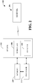
- Fig. 2 illustrates an example system 200 that facilitates space division multiple access channelization in a wireless communication system.
- System 200 can be configured to multiplex pilots and acknowledgements.
- System 200 can further be configured to facilitate Multiple Input-Multiple Output (MIMO) transmission and Space Division Multiple Access (SDMA) transmission at substantially the same time.
- MIMO Multiple Input-Multiple Output
- SDMA Space Division Multiple Access
- a base station has multiple antennas, referred to as transmit antennas, and a terminal has multiple antennas, referred to as receive antennas.
- the base station can transmit different signals from the different antennas and since there are multiple receive antennas, the signals, upon arrival, can be separated and understood at the receiving device. For example, in a two-by-two method the base station has two transmit antennas (T M1 and T M2 ) and the terminal has two receive antennas (R M1 and R M2 ).
- the receive antennas R M1 and R M2 will receive a linear combination of the transmitted signals T M1 and T M2 , which can include some interference or noise.
- a SDMA scheme instead of having one terminal with multiple antennas, there can be multiple users with one antenna and different beams are sent to different users. Multiple users may be scheduled simultaneously on the same time-frequency resource where their spatial signatures can be distinguished.
- SDMA a sector is split into spatial regions such that user devices in the different regions share the same channel resources, thereby achieving higher spatial reuse. In some other regions, no spatial reuse is allowed.
- Every unicast region is further subdivided into a set of narrower spatial beams so that a particular beam (or linear combination of beams) within a region can be applied to a particular user device, thereby increasing antenna gain to the user device and limiting spatial spread of the interference created by the transmission.
- the terminal demodulates one or more received channels based in part on pilots, which are some known symbols utilized by the terminal to estimate the channel (e.g., one antenna has one channel, two antennas have two channels, and so forth).
- pilots which are some known symbols utilized by the terminal to estimate the channel (e.g., one antenna has one channel, two antennas have two channels, and so forth).
- the terminal should multiplex the pilot coming from different antennas because the channel estimate from each antenna needs to be separated.
- the pilots from different antennas or both antennas can be multiplexed.
- different orthogonal codes can be utilized to transmit pilots corresponding to different antennas (in MIMO) or different beams (in SDMA).
- the codes can be DFT codes.
- system 200 includes a transmitter 202 that is in wireless communication with a receiver 204.
- Transmitter 202 can be a base station and receiver 204 can be a communication device, for example. It should be understood that system 200 could include one or more transmitters 202 and one or more receivers 204. However, only one receiver and only one transmitter are shown for purposes of simplicity.
- System 200 can be configured to assign different codes to different layers of the same user (MIMO) or to different receivers (SDMA). Thus, system 200 provides a structure that manages any combination of users and/or layers.
- Transmitter 202 can include a scheduler 206 that can be configured to assign or allocate resources. Such allocation can attempt to prevent pilot collisions, sent on a forward link, and/or collision of acknowledgments (ACKs) sent on a reverse link. Such resources can be allocated through utilization of a channel tree, which is a binary tree. Further information relating to channel trees with be discussed with reference to the below figures.
- Scheduler 206 can be configured to schedule transmissions to multiple receivers 204. Such transmissions can be scheduled to the receivers 204 on overlapping frequency resources for an overlapping time period on different spatial resources. A different sub-tree of a channel tree can be utilized to schedule the receivers 204.
- scheduler 206 can further be configured to provide distinct acknowledgement resources.
- UMB and each time a base station transmits a packet to a terminal, the terminal replies with an acknowledgement (ACK), which can be a positive ACK (packet received successfully) or a negative ACK (packet not successfully received).
- ACK acknowledgement
- the ACK is a channel dedicated to a terminal ( e.g., based on MAC ID).
- the ACK is dedicated to a channel, such that each base node on the channel tree has an associated ACK resource.
- receiver 204 can correspond that node to a resource on which an ACK can be transmitted on the downlink.
- subsequent ACKs can be sent on a different resource.
- an offseter 208 that can be configured to offset the pilot assignments for transmission to the receivers 204 by assigning a different offset code to each pilot.
- the pilots have different code offsets corresponding to different sub-trees so that the pilot transmissions do not overlap.
- the description of all sub-trees, except for the first sub-tree can be deferred to later overhead channels since this information is not necessary to demodulate control segment and overhead channels sent in non-MIMO non-SDMA mode.
- the offset can be at least a number of spatial dimensions utilized for transmission to one or more receiver 204. Since multiple receivers can be assigned the same channel ID, each user should be assigned a different pilot and pilot code or pilot signature (PS), which allows each receiver to estimate the channel.
- Scheduler 208 can assign the receivers with the respective pilot signature by specifying the receiver's first layer. This will be explained with the following example. There are four users, each user having one layer. Thus, for example, Receiver 1 can be provided Pilot Signature 0 (PS 0 ), Receiver 2 can be provided PS 1 , Receiver 3 can be provided PS 2 , and Receiver 4 can be provided PS 3 .
- offseter 208 can assign the first receiver PS 0 and the second receiver can be assigned PS 2 .
- first receiver is assigned PS 0 (and it has two layers)
- the receiver understands that it is to utilize PS 0 and PS 1 .
- PS 2 receiver understands that it is to utilize PS 2 and PS 3 . It should be understood that there could be a different number of receivers and different combinations of layers or antennas, as discussed above.
- offseter 208 attempts to send an offset and assigns the pilot signature that corresponds to the first layer of receiver 204. For the subsequent layers, the receiver 204 would increment the index by one, up to the number of layers.
- scheduler 206 can be configured to utilize scheduling techniques to reduce an assignment size without changing positions of ACKs. For example, scheduler 206 can first assign a subset of nodes by eliminating nodes after the last ACK and then assigning a subset of nodes by eliminating nodes before the first ACK.
- System 200 can include a processor 210 operatively connected to transmitter 202 (and/or memory 212) to execute instructions relating to multiplexing pilots and multiplexing assignments.
- Processor 210 can be a processor dedicated to assigning resources and/or generating information received by transmitter 202.
- Processor 210 can also be configured to execute instructions relating to scheduling transmissions to two or more terminals on overlapping frequency resources for overlapping time periods on different spatial resources.
- Processor 210 can schedule the transmissions so that pilots transmitted to the receivers utilize different codes that are offset from each other on the overlapping time or frequency resources. The code offsets can correspond to different sub-trees.
- Processor 210 can also be a processor that controls one or more components of system 200 and/or a processor that both analyzes and generates information received by transmitter 202 and controls one or more components of system 200.
- Memory 212 can store information related to the instructions executed by processor 210 and other suitable information related to SDMA and/or MIMO channelization in a wireless communication network. Memory 212 can further store protocols associated with taking action to control communication between transmitter 202 and receiver 204, etc ., such that system 200 can employ the stored protocols and/or algorithms to implement the various aspects disclosed herein.
- nonvolatile memory can include read only memory (ROM), programmable ROM (PROM), electrically programmable ROM (EPROM), electrically erasable ROM (EEPROM), or flash memory.
- Volatile memory can include random access memory (RAM), which acts as external cache memory.
- RAM is available in many forms such as synchronous RAM (DRAM), dynamic RAM (DRAM), synchronous DRAM (SDRAM), double data rate SDRAM (DDR SDRAM), enhanced SDRAM (ESDRAM), Synchlink DRAM (SLDRAM), and direct Rambus RAM (DRRAM).
- DRAM synchronous RAM
- DRAM dynamic RAM
- SDRAM synchronous DRAM
- DDR SDRAM double data rate SDRAM
- ESDRAM enhanced SDRAM
- SLDRAM Synchlink DRAM
- DRRAM direct Rambus RAM
- Memory 210 of the disclosed embodiments are intended to comprise, without being limited to, these and other suitable types of memory.
- FIG. 3 An example section of a channel tree structure 300 is illustrated in Fig. 3 .
- the channel tree 300 can be utilized by a base station in connection with allocating resources on a forward link within an OFDM/OFDMA wireless communications environment.
- the tree structure 300 represents a mapping of port space onto an available frequency region.
- Base nodes 302 through 316 of the tree structure 300 may correspond to non-overlapping contiguous tones. This allows access terminals scheduled within the same tree to be associated with orthogonality.
- a single tree structure can be employed to schedule communications within a sector, wherein terminals scheduled within the channel tree 300 are associated with channel orthogonality.
- multiple channel trees 300 can be used, wherein receivers 304 on disparate trees can utilize substantially similar time-frequency resources.
- Each node in the channel 300 represents a channel. Since there is frequency hopping, logically each receiver is assigned a node of the channel. In a frequency hopping pattern, at different times or frames of the same interlace, the nodes will map to different physical patterns to facilitate frequency hopping. The nodes map orthogonally such that no two nodes map to the same physical resource at the same time. Thus, in the channel tree 300 at any moment, the nodes map to a set of resources. Such mapping can be facilitated by base station and the mapping can be in a random fashion.
- Each node in the channel tree 300 has a node identifier (ID). When a node is assigned, the channel ID for that node is communicated to the terminal.
- ID node identifier
- a complete channel tree can have thirty-two nodes at the base level, which is the level illustrated by nodes 302-316.
- the next level higher in the tree e.g., the level represented by node 318) can have sixteen nodes.
- the next level higher can have eight nodes, another level higher has four nodes, then two nodes at the next level higher.
- the highest level is represented by one node.
- terminal has an assignment for node 304, that is the channel utilized by terminal. If a terminal is assigned node 318, receiver has two nodes 302 and 304. At any point in time on a given frame, if these two nodes 302 and 304 map in a hopping patter to this channel, receiver will transmit data on this physical tile, wherein each tile is sixteen tones.
- the channel tree 300 addresses frequency and moving up in the tree provides more frequency.
- the same resource is assigned to multiple receivers or multiple layers of the same receiver.
- base station will be transmitting two signals.
- MIMO the two signals are overlapping signals to the same terminal. The amount of resources does not change, it is the same resource and two signals are overlaid on the same resources.
- a base station has two antennas (T M1 and T M2 ) and a receiver has two antennas (R M1 and R M2 ).
- T M1 and T M2 the communication from T M1 would be received by R M1 and communication from T M2 would be received by R M2 , without any cross-talk between the communication.
- R M2 does not receive a signal from T M1, thus, "0" is in the lower portion of the matrix.
- the "1" in the lower portion of the matrix indicates that a signal from T M2 is received at R M2 .
- the pure signals received in an ideal system generally do not occur. What does generally occur is that both transmit antennas contribute to the communication received at both receive antennas.
- a terminal In a MIMO scheme, a terminal is obtaining two signals on the same resources.
- the same node In a SDMA scheme, the same node is assigned to different receivers.
- a first receiver and a second receiver are both assigned to a node and both receivers are provided with the same Node ID.
- the beams utilized in SDMA are different for each receiver and are separated in space, which minimizes leakage or crosstalk.
- the transmissions in MIMO can overlap utilizing a filter, as illustrated in the above matrix.
- the receiver should estimate the channel separately from a first antenna and a second antenna.
- the receiver estimates the channel that corresponds to different beams.
- receiver is assigned, not at the base level of a channel tree, but higher up in the tree (such as node 318 in Fig. 3 ). Then receiver can utilize either ACK resource (such as nodes 302 or 304 in Fig. 3 ). Generally, receiver 304 will choose the left-most base node to determine the resources. Thus, if user is assigned node 318, the ACK will be sent on node 302 rather than node 304.
- ACK resource such as nodes 302 or 304 in Fig. 3
- the ACK In the situation where the transmission is to multiple users on the same resources, the ACK is not transmitted on the same resources for the different users because the ACKs will collide.
- MCW multi-codeword
- the ACKs need to be sent separately since one layer might be decoded and the other layer not decoded. Thus, the ACK should be associated with the particular layer being acknowledged.
- a simple solution is to provide each node multiple ACKs. If there are two receivers, a first receiver will be instructed to use a first ACK and a second receiver will be instructed to use a second ACK. However, this increases the number of ACK resources needed, and the solution would be to increase the number of ACK resources.
- the users should be multiplexed so that the assignment is at least two nodes. For example, if a first user and a second user are assigned node 318 the first user can utilize node 302 to send an ACK and the second user can utilize node 304 to send an ACK.
- two terminals cannot be assigned the same base node because then the ACK would be assigned the same resources.
- two terminals can be assigned the same higher level node.
- channel tree structure 300 can be retained in matrix form or other suitable form to assist in scheduling access terminals in a wireless communications environment
- Fig. 4 illustrated is an exemplary graphical depiction of a mapping 400 between hop-ports and frequency regions. This is represented by the base nodes 302-316 of the tree structure 300 ( Fig. 3 ).
- the mapping can correspond to one particular permutation, as hop-ports can be subject to mapping to various frequency ranges given disparate permutations.
- the tree structure 300 can include eight base nodes 302, 304, 306, 308, 310, 312, 314, and 316. Accordingly, eight hop-ports may be mapped to eight different frequency ranges that are within an available frequency region during one hop permutation.
- a first hop-port (hp1) 402 can be mapped to a third frequency range (fr3) 404
- a second hop-port (hp2) 406 can be mapped to a first frequency range (fr1) 408,
- a third hop-port (hp3) 410 can be mapped to a sixth frequency range (fr6) 412, and so forth during the hop permutation.
- this mapping is for illustration purposes only. These mappings can be assigned randomly, pseudo-randomly, or through any other suitable means. Furthermore, the mappings can be re-assigned during particular time intervals and/or according to a permutation schedule. It is also to be understood that these mappings enable access terminals that are associated with the hop-ports within a channel tree to remain related to orthogonal channels ( e.g., the frequency ranges can be created in such a way to maintain orthogonality).
- the mappings may be replaced by subcarrier mappings or subcarrier sets, which in one aspect, may comprise at least two groups of subcarriers.
- the groups of subcarriers may be disjoint from each other, while the subcarriers in each group are contiguous with each other. In such a way, resources may be efficiently provided while facilitating some diversity for each assignment.
- Fig. 5 illustrates a tree structure that places certain restrictions on the use of the traffic channels for an orthogonal system. For each traffic channel that is assigned, all traffic channels that are subsets (or descendants) of the assigned traffic channel and all traffic channels for which the assigned traffic channel is a subset are restricted. The restricted traffic channels are not used concurrently with the assigned traffic channel so that no two traffic channels use the same subcarrier set at the same time.
- a channel tree includes M multiple sub-trees. There are four sub-trees illustrated, labeled Sub-Tree 0 (502), Sub-Tree 1 (504), Sub-Tree 2 (506) and Sub-Tree 3 (508).
- Sub-Tree 0 502
- Sub-Tree 1 504
- Sub-Tree 2 506
- Sub-Tree 3 508
- M M
- M max ⁇ M 1 + ... + M n ) where n is the number of spatially multiplexed access terminals and M k is the MIMO order ( e.g., the number of layers or streams) per access terminal.
- each sub-tree maps to the same time-frequency resources.
- each sub-tree may have the same hopping pattern. For example, access terminals scheduled on the same nodes of any two sub-trees hop together.
- pilots transmitted to each user being transmitted to simultaneously, may collide with each other if the pilots are transmitted on the same exact resources.
- a collision avoidance algorithm or technique may be utilized by a scheduler or sector to prevent pilot collision.
- this technique utilizes a sub-tree index offset between access terminals in SDMA.
- this offset is not less than the total number of spatial dimensions between the access terminals that are being scheduled for overlapping transmission. For example, when four access terminals are to receive one stream each, the offsets for pilot resources are 0, 1, 2, or 3 on each tree, with each tree using a different offset.
- one tree would have an offset of 0 and another would have an offset of 2.
- the pilots for access terminal 1 are sent on the same traffic resources (e.g ., corresponding to the same base nodes) as the pilots for terminal 2 .
- the terminals utilize different code offsets corresponding to different subtrees. The different code offsets generate different pilot signatures and, therefore are not "colliding.” In an example, where there are two SIMO access terminals being scheduled, any two offsets may be utilized.
- the technique described above provides different pilot signatures for every ⁇ layer, access terminal ⁇ pair. This also may be enhanced by using a spreading or scrambling code on the pilots that utilizes the offsets for altering the code or scrambling sequence.
- Fig. 6 illustrates aspects of SDMA transmission of acknowledgements (ACKs) by access terminals for reverse link, to the access point or sector, for the forward link SDMA transmission.
- Fig. 7 illustrates aspects to mitigate collisions of the acknowledgements sent on the reverse link, which can cause throughput issues for the forward link
- a scheduler or sector can provide distinct acknowledgement resources for every ⁇ layer, access terminal ⁇ pair.
- N k N.
- An assignment of individual access terminals can be reduced without changing its acknowledgement resource location. Thus, this can be facilitated by eliminating nodes (illustrated within dotted circle 702) after the node that carries the last acknowledgment segment of this access terminal. In accordance with another aspect, this may be augmented by next eliminating nodes (illustrated within dotted circle 704) before the node that carries the last acknowledgment segment of this access terminal.
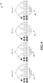
- a four sub-tree structure 800 for four access terminals illustrated at 802, 804, 806, and 808.
- Each of the four access terminals 802-808 have one stream each being transmitted over an overlapping time period for overlapping frequency resources.
- a combination of acknowledgment resource, reverse link, and pilot resource assignment, forward link is assigned, so that each sub-tree, and thus each user, is assigned a different offset then each other sub-tree.
- the different code offsets provide different pilot signatures to mitigate "colliding" of pilots.
- the pilots for the different terminals are sent on the same nodes ( e.g ., similar to traffic) but use different code offsets (and therefore different pilot signatures) to mitigate collision.
- a combination of acknowledgment resource, reverse link, and pilot resource assignment, forward link is assigned, so that each sub-tree, and thus each user, is assigned a different offset then each other sub-tree that is being used.
- Each terminal 902 and 904 utilizes different code offsets (e.g ., different pilot signatures) to mitigate collision of ACKs.
- each terminal 902, 904 receives pilots that are sent on the same node.
- a four sub-tree structure 1000 for three access terminals where two have one stream being transmitted and other has two streams over an overlapping time period for overlapping frequency resources.
- a combination of acknowledgment resource, reverse link, and pilot resource assignment, forward link is assigned, so that each sub-tree, and thus each user, is assigned a different offset then each other sub-tree that is being used.
- the base node on each tree for the acknowledgment and pilot as illustrated as different.
- each sub-tree has assignments of the acknowledgment and pilot resources to the same node, this need not be the case and the acknowledgement and pilot node may be different on each tree, provided each sub-tree assignment is offset from each other sub-tree for each node.
- a sub-tree structure 1100 illustrated is another exemplary sub-tree structure 1100.
- the number of sub-trees can be reduced from the maximum number of spatial dimensions down to the maximum number of spatially multiplexed (SM), SDMA, users. This can be achieved by labeling the sub-trees with a non-contiguous indexes.
- SM spatially multiplexed
- a tree has two-sub-trees, labeled Sub-Tree 0 (1102) and Sub-Tree 1 (1104), which can support up to two SM access terminals with up to a second order MIMO or no SM, ( e.g., one user with up to fourth order MIMO).
- a specific channel may be utilized to provide a description of the primary sub-tree and the total tree size.
- This channel may be a frame or superframe preamble.
- the information contained therein should be sufficient to demodulate pages and system information on a data channel.
- the offsets may be transmitted on different sub-trees carried as part of a channel information message. In an aspect, the offsets may be sent approximately every 200ms.
- Fig. 12 illustrates a method 1200 for facilitating channelization in a wireless communication system. While, for purposes of simplicity of explanation, the method is shown and described as a series of blocks, it is to be understood and appreciated that the claimed subject matter is not limited by the number or order of blocks, as some blocks may occur in different orders and/or concurrently with other blocks from what is depicted and described herein. Moreover, not all illustrated blocks may be required to implement the methods described hereinafter. It is to be appreciated that the functionality associated with the blocks may be implemented by software, hardware, a combination thereof or any other suitable means (e.g . device, system, process, component).
- Method 1200 starts, at 1202, when a transmission is scheduled.
- This transmission can be scheduled for at two or more terminals on overlapping frequency resources and for an overlapping time period of different spatial resources.
- the overlapping frequency resources can partially overlap or completely overlap.
- Each of the two or more terminals can be scheduled utilizing a different sub-tree of a channel tree.
- acknowledgements of the transmissions to the two or more terminals are scheduled so that the acknowledgement is transmitted on non-overlapping time or frequency resources.
- different code offsets are utilized for pilots sent to the at least two terminals.
- the different code offsets can correspond to different sub-trees. This offset can be on the overlapping time or frequency resources.
- the offset creates different pilot signatures and can mitigate the chances of the pilot transmissions overlapping.
- the pilots can utilize a code that is offset by at least a number of spatial dimensions utilized for transmission to one or more of the terminals.
- the pilot signatures can be assigned to channel sub-trees in a non-contiguous manner. In accordance with some aspects, the number of sub-trees is less than a number of available dimensions.
- the description of all sub-trees (except for the first sub-tree) can be deferred to later overhead channels since this information is not necessary to demodulate control segment and overhead channels send in non-MIMO non-SDMA mode.
- method 1200 can utilize a scheduling technique to reduce the assignment size without changing positions of ACKS. To facilitate this reduction, method 1200 can assign a subset of nodes by eliminating nodes after the node that carries the last acknowledgment segment of this access terminal. After these nodes are eliminated, method 1200 can assign a subset of nodes by eliminating nodes before the node that carries the last acknowledgment segment of this access terminal.
- a block diagram of an embodiment of a transmitter system 1310 and a receiver system 1350 in a MIMO system 1300 is illustrated.
- traffic data for a number of data streams is provided from a data source 1312 to transmit (TX) data processor 1314.
- TX data processor 1314 formats, codes, and interleaves the traffic data for each data stream based on a particular coding scheme selected for that data stream to provide coded data.
- the coded data for each data stream may be multiplexed with pilot data using OFDM techniques.
- the pilot data is typically a known data pattern that is processed in a known manner and may be used at the receiver system to estimate the channel response.
- the multiplexed pilot and coded data for each data stream is then modulated (i.e., symbol mapped) based on a particular modulation scheme (e.g., BPSK, QSPK, M-PSK, or MQAM) selected for that data stream to provide modulation symbols.
- a particular modulation scheme e.g., BPSK, QSPK, M-PSK, or MQAM
- the data rate, coding, and modulation for each data stream may be determined by instructions performed on provided by processor 1330.
- TX processor 1320 may further process the modulation symbols (e.g ., for OFDM).
- TX processor 1320 then provides NT modulation symbol streams to NT transmitters (TMTR) 1322a through 1322t.
- TMTR NT transmitters
- Each transmitter 1322 receives and processes a respective symbol stream to provide one or more analog signals, and further conditions (e.g., amplifies, filters, and upconverts) the analog signals to provide a modulated signal suitable for transmission over the MIMO channel.
- NT modulated signals from transmitters 1322a through 1322t are then transmitted from NT antennas 1324a through 1324t, respectively.
- the transmitted modulated signals are received by NR antennas 1352a through 1352r and the received signal from each antenna 1352 is provided to a respective receiver (RCVR) 1354.
- Each receiver 1354 conditions (e.g., filters, amplifies, and downconverts) a respective received signal, digitizes the conditioned signal to provide samples, and further processes the samples to provide a corresponding "received" symbol stream.
- An RX data processor 1360 then receives and processes the NR received symbol streams from NR receivers 1354 based on a particular receiver processing technique to provide NT "detected" symbol streams.
- the processing by RX data processor 1360 is described in further detail below.
- Each detected symbol stream includes symbols that are estimates of the modulation symbols transmitted for the corresponding data stream.
- RX data processor 1360 then demodulates, deinterleaves, and decodes each detected symbol stream to recover the traffic data for the data stream.
- the processing by RX data processor 1318 is complementary to that performed by TX processor 1320 and TX data processor 1314 at transmitter system 1310.
- the channel response estimate generated by RX processor 1360 may be used to perform space, space/time processing at the receiver, adjust power levels, change modulation rates or schemes, or other actions.
- RX processor 1360 may further estimate the signal-to-noise-and-interference ratios (SNRs) of the detected symbol streams, and possibly other channel characteristics, and provides these quantities to a processor 1370.
- SNRs signal-to-noise-and-interference ratios
- RX data processor 1360 or processor 1370 may further derive an estimate of the "operating" SNR for the system.
- Processor 1370 then provides channel state information (CSI), which may comprise various types of information regarding the communication link and/or the received data stream.
- CSI may comprise only the operating SNR.
- the CSI is then processed by a TX data processor 1378, modulated by a modulator 1380, conditioned by transmitters 1354a through 1354r, and transmitted back to transmitter system 1310.
- the modulated signals from receiver system 1350 are received by antennas 1324, conditioned by receivers 1322, demodulated by a demodulator 1340, and processed by a RX data processor 1342 to recover the CSI reported by the receiver system.
- the reported CSI is then provided to processor 1330 and used to (1) determine the data rates and coding and modulation schemes to be used for the data streams and (2) generate various controls for TX data processor 1314 and TX processor 1320.
- the CSI may be utilized by processor 1370 to determine modulation schemes and/or coding rates for transmission, along with other information. This may then be provided to the transmitter that uses this information, which may be quantized, to provide later transmissions to the receiver.
- Processors 1330 and 1370 direct the operation at the transmitter and receiver systems, respectively.
- Memories 1332 and 1372 provide storage for program codes and data used by processors 1330 and 1370, respectively.
- receiver processing techniques may be used to process the NR received signals to detect the NT transmitted symbol streams.
- These receiver processing techniques may be grouped into two primary categories (i) spatial and space-time receiver processing techniques (which are also referred to as equalization techniques); and (ii) “successive nulling/equalization and interference cancellation” receiver processing technique (which is also referred to as “successive interference cancellation” or “successive cancellation” receiver processing technique).
- broadcast and multicast may be applied to the same transmission. That is, a broadcast need not be sent to all terminals of an access point or sector.
- the processing units at a transmitter may be implemented within one or more application specific integrated circuits (ASICs), digital signal processors (DSPs), digital signal processing devices (DSPDs), programmable logic devices (PLDs), field programmable gate arrays (FPGAs), processors, controllers, micro-controllers, microprocessors, electronic devices, other electronic units designed to perform the functions described herein, or a combination thereof.
- ASICs application specific integrated circuits
- DSPs digital signal processors
- DSPDs digital signal processing devices
- PLDs programmable logic devices
- FPGAs field programmable gate arrays
- processors controllers, micro-controllers, microprocessors, electronic devices, other electronic units designed to perform the functions described herein, or a combination thereof.
- the processing units at a receiver may also be implemented within one or more ASICs, DSPs, processors, and so on.
- the transmission techniques may be implemented with instructions (e.g., procedures, functions, and so on) that may be utilized to perform functions described herein.
- the instructions may be stored in a memory (e.g., memory 1330, 1372x or 1372y in FIG. 13 ) or other computer program product and executed by a processor (e.g., processor 1332, 1370x or 1370y).
- the memory may be implemented within the processor or external to the processor.
- channels herein refers to information or transmission types that may be transmitted by the access point or access terminal. It does not require or utilize fixed or predetermined blocks of subcarriers, time periods, or other resources dedicated to such transmissions.
- Fig. 14 illustrates a system 1400 for space division multiple access channelization.
- system 1400 may reside at least partially within a base station.
- system 1400 is represented as including functional blocks, which may be functional blocks that represent functions implemented by a processor, software, or combination thereof ( e.g ., firmware).
- System 1400 includes a logical grouping 1402 of electrical components that can act separately or in conjunction.
- logical grouping 1402 can include an electrical component for scheduling transmissions 1404. The transmissions can be scheduled to two or more terminals on overlapping frequency resources for overlapping time periods on different spatial resources.
- include in logical grouping 1402 can be an electrical component for utilizing different code offsets for the pilot assignments 1406.
- the different code offsets correspond to different sub-trees and produce different pilot signatures.
- the pilot assignments can be offset so that the pilot transmissions do not overlap.
- electrical component 1404 includes a component for scheduling each of the terminals utilizing a different sub-tree of a channel tree.
- electrical component 1406 includes a component for offsetting the pilots by at least a number of spatial dimensions utilized for transmission to at least one of the terminals.
- system 1400 can include a memory 1408 that retains instructions for executing functions associated with electrical components 1404 and 1406 or other components. While shown as being external to memory 1408, it is to be understood that one or more of electrical components 1404 and 1406 may exist within memory 1408.
- DSP digital signal processor
- ASIC application specific integrated circuit
- FPGA field programmable gate array
- a general purpose processor may be a microprocessor, but in the alternative, the processor may be any conventional processor, controller, microcontroller, or state machine.
- a processor may also be implemented as a combination of computing devices, e.g., a combination of a DSP and a microprocessor, a plurality of microprocessors, one or more microprocessors in conjunction with a DSP core, or any other such configuration.
- a software module may reside in RAM memory, flash memory, ROM memory, EPROM memory, EEPROM memory, registers, hard disk, a removable disk, a CD-ROM, or any other form of storage medium known in the art.
- An exemplary storage medium is coupled to the processor such the processor can read information from, and write information to, the storage medium.
- the storage medium may be integral to the processor.
- the processor and the storage medium may reside in an ASIC.
- the ASIC may reside in a user terminal.
- the processor and the storage medium may reside as discrete components in a user terminal.
- the techniques described herein may be implemented with modules (e.g ., procedures, functions, and so on) that perform the functions described herein.
- the software codes may be stored in memory units and executed by processors.
- the memory unit may be implemented within the processor or external to the processor, in which case it can be communicatively coupled to the processor through various means as is known in the art.
- various aspects or features described herein may be implemented as a method, apparatus, or article of manufacture using standard programming and/or engineering techniques.
- article of manufacture as used herein is intended to encompass a computer program accessible from any computer-readable device, carrier, or media.
- computer-readable media can include but are not limited to magnetic storage devices (e.g ., hard disk, floppy disk, magnetic strips, etc .), optical disks (e.g., compact disk (CD), digital versatile disk (DVD), etc .), smart cards, and flash memory devices (e.g., EPROM, card, stick, key drive, etc .).
- various storage media described herein can represent one or more devices and/or other machine-readable media for storing information.
- the term "machine-readable medium” can include, without being limited to, wireless channels and various other media capable of storing, containing, and/or carrying instruction(s) and/or data.
Landscapes
- Engineering & Computer Science (AREA)
- Computer Networks & Wireless Communication (AREA)
- Signal Processing (AREA)
- Mobile Radio Communication Systems (AREA)
- Radio Transmission System (AREA)
Applications Claiming Priority (3)
| Application Number | Priority Date | Filing Date | Title |
|---|---|---|---|
| US82882106P | 2006-10-10 | 2006-10-10 | |
| US11/869,589 US7903615B2 (en) | 2006-10-10 | 2007-10-09 | Space division multiple access channelization in wireless communication systems |
| PCT/US2007/081013 WO2008045980A2 (en) | 2006-10-10 | 2007-10-10 | Space division multiple access channelization in wireless communication systems |
Publications (2)
| Publication Number | Publication Date |
|---|---|
| EP2095559A2 EP2095559A2 (en) | 2009-09-02 |
| EP2095559B1 true EP2095559B1 (en) | 2017-12-27 |
Family
ID=39274878
Family Applications (1)
| Application Number | Title | Priority Date | Filing Date |
|---|---|---|---|
| EP07853926.9A Active EP2095559B1 (en) | 2006-10-10 | 2007-10-10 | Space division multiple access channelization in wireless communication systems |
Country Status (14)
| Country | Link |
|---|---|
| US (1) | US7903615B2 (ko) |
| EP (1) | EP2095559B1 (ko) |
| JP (2) | JP5575478B2 (ko) |
| KR (1) | KR101190886B1 (ko) |
| CN (1) | CN101523793B (ko) |
| AU (1) | AU2007307656B2 (ko) |
| BR (1) | BRPI0718037B1 (ko) |
| CA (1) | CA2663694C (ko) |
| IL (1) | IL197603A0 (ko) |
| MX (1) | MX2009003682A (ko) |
| NO (1) | NO20091663L (ko) |
| RU (1) | RU2420884C2 (ko) |
| TW (1) | TWI367656B (ko) |
| WO (1) | WO2008045980A2 (ko) |
Families Citing this family (44)
| Publication number | Priority date | Publication date | Assignee | Title |
|---|---|---|---|---|
| USRE50183E1 (en) * | 2007-04-11 | 2024-10-22 | Telefonaktiebolaget Lm Ericsson (Publ) | Method for implicit conveying of uplink feedback information |
| US9137821B2 (en) * | 2007-05-02 | 2015-09-15 | Qualcomm Incorporated | Flexible signaling of resources on a control channel |
| US8130780B2 (en) | 2007-06-15 | 2012-03-06 | Futurewei Technologies, Inc. | Method and apparatus for assigning resources in a wireless system with multiple regions |
| US8265029B2 (en) * | 2007-06-15 | 2012-09-11 | Futurewei Technologies, Inc. | Method and apparatus for assigning resources in a wireless system |
| US20080310359A1 (en) * | 2007-06-15 | 2008-12-18 | Mcbeath Sean Michael | Method and Apparatus for Sharing Resources in a Wireless System |
| US8614985B2 (en) * | 2007-06-15 | 2013-12-24 | Futurewei Technologies, Inc. | Method and apparatus for sharing a group resource in a wireless SDMA system |
| US9544911B2 (en) * | 2007-08-10 | 2017-01-10 | Futurewei Technologies, Inc. | System and method for assigning communications resources in a wireless communications system |
| US8254942B2 (en) * | 2007-11-27 | 2012-08-28 | Futurewei Technologies, Inc. | System and method for resource allocation in a wireless communications system |
| US8483650B2 (en) * | 2008-02-06 | 2013-07-09 | At&T Mobility Ii Llc | Management of a multi-application mobile carrier tree |
| US8259662B2 (en) * | 2008-02-19 | 2012-09-04 | Futurewei Technologies | Method and apparatus for assigning persistent resources dynamically in a wireless communication system |
| US20090257420A1 (en) * | 2008-04-10 | 2009-10-15 | Honeywell International Inc. | Process Control System With Enhanced Communication Throughput Using Frequency Agility |
| US8848816B2 (en) * | 2008-05-21 | 2014-09-30 | Qualcomm Incorporated | Method and apparatus for determining the spatial channels in a spatial division multiple access (SDMA)-based wireless communication system |
| CN101588604B (zh) * | 2008-05-21 | 2011-07-06 | 华为技术有限公司 | 通信网络ack信道的分配方法、装置及系统 |
| US8780817B2 (en) * | 2008-09-22 | 2014-07-15 | Qualcomm Incorporated | Apparatus and method for reducing overhead for communications |
| US8259664B2 (en) * | 2008-11-14 | 2012-09-04 | Samsung Electronics Co., Ltd. | Method and apparatus for resource allocation in a communication system |
| GB2474794B (en) | 2008-11-27 | 2011-06-15 | Ipwireless Inc | Communication system, communication units, and method for employing a pilot transmission scheme |
| US9019903B2 (en) * | 2008-12-08 | 2015-04-28 | Qualcomm Incorporated | Optimization to support uplink coordinated multi-point |
| US20100227612A1 (en) * | 2009-03-09 | 2010-09-09 | Qualcomm Incorporated | Cell detection for mobile location with grouping diversity |
| KR101427804B1 (ko) * | 2012-09-25 | 2014-08-07 | 국방과학연구소 | 디지털 수신기 및 그것의 신호 처리 방법 |
| EP3284197B1 (en) * | 2015-05-08 | 2019-02-27 | Huawei Technologies Co., Ltd. | Apparatus and method for controlling resource allocation in a wireless communication network |
| US11082176B2 (en) * | 2016-11-04 | 2021-08-03 | Futurewei Technologies, Inc. | System and method for transmitting a sub-space selection |
| US10432272B1 (en) | 2018-11-05 | 2019-10-01 | XCOM Labs, Inc. | Variable multiple-input multiple-output downlink user equipment |
| US10659112B1 (en) | 2018-11-05 | 2020-05-19 | XCOM Labs, Inc. | User equipment assisted multiple-input multiple-output downlink configuration |
| US10812216B2 (en) | 2018-11-05 | 2020-10-20 | XCOM Labs, Inc. | Cooperative multiple-input multiple-output downlink scheduling |
| US10756860B2 (en) | 2018-11-05 | 2020-08-25 | XCOM Labs, Inc. | Distributed multiple-input multiple-output downlink configuration |
| KR20210087089A (ko) | 2018-11-27 | 2021-07-09 | 엑스콤 랩스 인코퍼레이티드 | 넌-코히어런트 협력 다중 입출력 통신 |
| US10756795B2 (en) | 2018-12-18 | 2020-08-25 | XCOM Labs, Inc. | User equipment with cellular link and peer-to-peer link |
| US11063645B2 (en) | 2018-12-18 | 2021-07-13 | XCOM Labs, Inc. | Methods of wirelessly communicating with a group of devices |
| US11330649B2 (en) | 2019-01-25 | 2022-05-10 | XCOM Labs, Inc. | Methods and systems of multi-link peer-to-peer communications |
| US10756767B1 (en) | 2019-02-05 | 2020-08-25 | XCOM Labs, Inc. | User equipment for wirelessly communicating cellular signal with another user equipment |
| US10756782B1 (en) | 2019-04-26 | 2020-08-25 | XCOM Labs, Inc. | Uplink active set management for multiple-input multiple-output communications |
| US11032841B2 (en) | 2019-04-26 | 2021-06-08 | XCOM Labs, Inc. | Downlink active set management for multiple-input multiple-output communications |
| US10735057B1 (en) | 2019-04-29 | 2020-08-04 | XCOM Labs, Inc. | Uplink user equipment selection |
| US10686502B1 (en) | 2019-04-29 | 2020-06-16 | XCOM Labs, Inc. | Downlink user equipment selection |
| CN114128382B (zh) * | 2019-07-08 | 2025-12-05 | 瑞典爱立信有限公司 | 用于无线通信的方法和设备 |
| US11411778B2 (en) | 2019-07-12 | 2022-08-09 | XCOM Labs, Inc. | Time-division duplex multiple input multiple output calibration |
| US11411779B2 (en) | 2020-03-31 | 2022-08-09 | XCOM Labs, Inc. | Reference signal channel estimation |
| US12088499B2 (en) | 2020-04-15 | 2024-09-10 | Virewirx, Inc. | System and method for reducing data packet processing false alarms |
| KR20230015932A (ko) | 2020-05-26 | 2023-01-31 | 엑스콤 랩스 인코퍼레이티드 | 간섭-인식 빔포밍 |
| CA3195885A1 (en) | 2020-10-19 | 2022-04-28 | XCOM Labs, Inc. | Reference signal for wireless communication systems |
| WO2022093988A1 (en) | 2020-10-30 | 2022-05-05 | XCOM Labs, Inc. | Clustering and/or rate selection in multiple-input multiple-output communication systems |
| CN116648867A (zh) | 2020-12-16 | 2023-08-25 | 艾斯康实验室公司 | 具有准全向波束和定向波束的无线通信 |
| CN113055457B (zh) * | 2021-03-09 | 2024-01-09 | 百果园技术(新加坡)有限公司 | 接入控制与数据转发方法、装置、电子设备及存储介质 |
| WO2022241436A1 (en) | 2021-05-14 | 2022-11-17 | XCOM Labs, Inc. | Scrambling identifiers for wireless communication systems |
Family Cites Families (24)
| Publication number | Priority date | Publication date | Assignee | Title |
|---|---|---|---|---|
| US6539050B1 (en) * | 1997-06-26 | 2003-03-25 | Hughes Electronics Corporation | Method for transmitting wideband signals via a communication system adapted for narrow-band signal transmission |
| US6275483B1 (en) | 1998-09-03 | 2001-08-14 | Texas Instruments Incorporated | Fast and accurate identification of spread spectrum signals |
| EP1035676B1 (en) * | 1999-03-10 | 2005-10-19 | Lucent Technologies Inc. | Communicating code branch allocation for CDMA system |
| KR100755038B1 (ko) * | 1999-08-05 | 2007-09-06 | 한국전자통신연구원 | 직교 부호 도약 다중화 통신 방식 및 장치 |
| GB0110125D0 (en) | 2001-04-25 | 2001-06-20 | Koninkl Philips Electronics Nv | Radio communication system |
| RU2272365C2 (ru) * | 2001-05-28 | 2006-03-20 | Нокиа Корпорейшн | Оптимальная маршрутизация, когда два или более сетевых элемента объединены в один элемент |
| GB2382275B (en) * | 2001-08-11 | 2004-06-09 | Samsung Electronics Co Ltd | Method for transmitting/receiving orthogonal variable spreading factor codes in a communication system |
| JP2004072506A (ja) * | 2002-08-07 | 2004-03-04 | Matsushita Electric Ind Co Ltd | 送信装置、受信装置及び送信方法 |
| US8208364B2 (en) * | 2002-10-25 | 2012-06-26 | Qualcomm Incorporated | MIMO system with multiple spatial multiplexing modes |
| US7099623B2 (en) * | 2002-12-20 | 2006-08-29 | Qualcomm Incorporated | Managing searcher and tracker resources in a wireless communication device |
| JP4183706B2 (ja) * | 2003-07-29 | 2008-11-19 | 富士通株式会社 | Ofdmシステムにおけるパイロット多重方法及び送受信装置 |
| WO2005099125A1 (en) | 2004-04-07 | 2005-10-20 | Lg Electronics Inc. | Frame structure of uplink control information transmission channel for mimo system |
| DE602004011479T2 (de) * | 2004-05-04 | 2009-02-05 | Alcatel Lucent | Verfahren zur Interzell-Interferenzskoordination mit Leistungsplanung in einem OFDM-Mobilkommunikationssystem |
| EP1594330A1 (en) * | 2004-05-04 | 2005-11-09 | Alcatel | Methods for terminal assisted coordinated radio serving and interference avoidance in OFDM mobile communication system |
| DE102004028703A1 (de) | 2004-06-14 | 2005-12-29 | Siemens Ag | Verfahren zur Zuweisung von Übertragungskapazitäten bei einer Signalübertragung, Basisstation und mobiles Endgerät |
| US7593473B2 (en) * | 2004-12-01 | 2009-09-22 | Bae Systems Information And Electronic Systems Integration Inc. | Tree structured multicarrier multiple access systems |
| US7512412B2 (en) | 2005-03-15 | 2009-03-31 | Qualcomm, Incorporated | Power control and overlapping control for a quasi-orthogonal communication system |
| US8446892B2 (en) | 2005-03-16 | 2013-05-21 | Qualcomm Incorporated | Channel structures for a quasi-orthogonal multiple-access communication system |
| US8582509B2 (en) * | 2005-10-27 | 2013-11-12 | Qualcomm Incorporated | Scalable frequency band operation in wireless communication systems |
| EP1962537B1 (en) * | 2005-12-14 | 2011-05-25 | Mitsubishi Electric Corporation | Scheduling method, base station and terminal |
| JP5092350B2 (ja) * | 2006-10-26 | 2012-12-05 | 富士通株式会社 | パイロット信号伝送方法及び移動通信システム |
| US8379578B2 (en) * | 2006-12-01 | 2013-02-19 | Qualcomm Incorporated | Control signal transmission for wireless communication systems |
| US7796698B2 (en) * | 2007-06-04 | 2010-09-14 | Telefonaktiebolaget Lm Ericsson (Publ) | Interference suppression in a multicarrier receiver |
| US20100098042A1 (en) * | 2008-10-21 | 2010-04-22 | Paul Wilkinson Dent | Using the same multiplexed radio resource for pilot and information signals |
-
2007
- 2007-10-09 US US11/869,589 patent/US7903615B2/en active Active
- 2007-10-10 JP JP2009532568A patent/JP5575478B2/ja not_active Expired - Fee Related
- 2007-10-10 WO PCT/US2007/081013 patent/WO2008045980A2/en not_active Ceased
- 2007-10-10 EP EP07853926.9A patent/EP2095559B1/en active Active
- 2007-10-10 KR KR1020097009646A patent/KR101190886B1/ko active Active
- 2007-10-10 AU AU2007307656A patent/AU2007307656B2/en not_active Expired - Fee Related
- 2007-10-10 CA CA2663694A patent/CA2663694C/en active Active
- 2007-10-10 RU RU2009117599/09A patent/RU2420884C2/ru active
- 2007-10-10 MX MX2009003682A patent/MX2009003682A/es unknown
- 2007-10-10 BR BRPI0718037-3A patent/BRPI0718037B1/pt active IP Right Grant
- 2007-10-10 CN CN2007800377839A patent/CN101523793B/zh active Active
- 2007-10-11 TW TW096138068A patent/TWI367656B/zh active
-
2009
- 2009-03-15 IL IL197603A patent/IL197603A0/en unknown
- 2009-04-27 NO NO20091663A patent/NO20091663L/no not_active Application Discontinuation
-
2013
- 2013-03-13 JP JP2013050948A patent/JP2013168957A/ja not_active Withdrawn
Also Published As
| Publication number | Publication date |
|---|---|
| CA2663694C (en) | 2012-12-11 |
| TW200833131A (en) | 2008-08-01 |
| IL197603A0 (en) | 2009-12-24 |
| AU2007307656B2 (en) | 2010-12-16 |
| JP2010506546A (ja) | 2010-02-25 |
| RU2420884C2 (ru) | 2011-06-10 |
| KR20090068362A (ko) | 2009-06-26 |
| KR101190886B1 (ko) | 2012-10-12 |
| CA2663694A1 (en) | 2008-04-17 |
| US20080084843A1 (en) | 2008-04-10 |
| TWI367656B (en) | 2012-07-01 |
| MX2009003682A (es) | 2009-04-23 |
| BRPI0718037B1 (pt) | 2020-02-18 |
| WO2008045980A2 (en) | 2008-04-17 |
| NO20091663L (no) | 2009-04-27 |
| JP5575478B2 (ja) | 2014-08-20 |
| JP2013168957A (ja) | 2013-08-29 |
| CN101523793A (zh) | 2009-09-02 |
| HK1136120A1 (en) | 2010-06-18 |
| US7903615B2 (en) | 2011-03-08 |
| CN101523793B (zh) | 2013-03-27 |
| EP2095559A2 (en) | 2009-09-02 |
| RU2009117599A (ru) | 2010-11-20 |
| AU2007307656A1 (en) | 2008-04-17 |
| BRPI0718037A2 (pt) | 2014-11-25 |
| WO2008045980A3 (en) | 2008-07-10 |
Similar Documents
| Publication | Publication Date | Title |
|---|---|---|
| EP2095559B1 (en) | Space division multiple access channelization in wireless communication systems | |
| JP2010506546A5 (ko) | ||
| EP2030395B1 (en) | Signal acquisition for wireless communication systems | |
| EP2070274B1 (en) | Method and system for de-assignment of resources in a wireless communication system | |
| CN104348606A (zh) | 通信系统中的控制信息分配方法 | |
| EP1992132B1 (en) | Deassignment of resources in a wireless communication system | |
| CN101507220A (zh) | 用于灵活导频模式的方法和装置 | |
| HK1136120B (en) | Space division multiple access channelization in wireless communication systems | |
| CN121079920A (zh) | 无线通信方法及相关产品 | |
| CN121399878A (zh) | 无线通信方法及相关产品 | |
| Nagaraj et al. | Project IEEE 802.20 Working Group on Mobile Broadband Wireless Access< http://grouper. ieee. org/groups/802/20/> Title UMBFDD Draft Technology Overview | |
| HK1136711A (en) | Signal acquisition for wireless communication systems | |
| HK1136142A (en) | Control channel for wireless communication systems |
Legal Events
| Date | Code | Title | Description |
|---|---|---|---|
| PUAI | Public reference made under article 153(3) epc to a published international application that has entered the european phase |
Free format text: ORIGINAL CODE: 0009012 |
|
| 17P | Request for examination filed |
Effective date: 20090430 |
|
| AK | Designated contracting states |
Kind code of ref document: A2 Designated state(s): AT BE BG CH CY CZ DE DK EE ES FI FR GB GR HU IE IS IT LI LT LU LV MC MT NL PL PT RO SE SI SK TR |
|
| DAX | Request for extension of the european patent (deleted) | ||
| 17Q | First examination report despatched |
Effective date: 20141006 |
|
| REG | Reference to a national code |
Ref country code: DE Ref legal event code: R079 Ref document number: 602007053582 Country of ref document: DE Free format text: PREVIOUS MAIN CLASS: H04L0001180000 Ipc: H04B0007060000 |
|
| RIC1 | Information provided on ipc code assigned before grant |
Ipc: H04B 7/06 20060101AFI20170607BHEP Ipc: H04W 16/28 20090101ALN20170607BHEP Ipc: H04L 1/00 20060101ALN20170607BHEP Ipc: H04L 1/16 20060101ALI20170607BHEP Ipc: H04W 72/12 20090101ALI20170607BHEP |
|
| GRAP | Despatch of communication of intention to grant a patent |
Free format text: ORIGINAL CODE: EPIDOSNIGR1 |
|
| RIC1 | Information provided on ipc code assigned before grant |
Ipc: H04L 1/00 20060101ALN20170609BHEP Ipc: H04B 7/06 20060101AFI20170609BHEP Ipc: H04W 16/28 20090101ALN20170609BHEP Ipc: H04W 72/12 20090101ALI20170609BHEP Ipc: H04L 1/16 20060101ALI20170609BHEP |
|
| INTG | Intention to grant announced |
Effective date: 20170717 |
|
| GRAS | Grant fee paid |
Free format text: ORIGINAL CODE: EPIDOSNIGR3 |
|
| GRAA | (expected) grant |
Free format text: ORIGINAL CODE: 0009210 |
|
| AK | Designated contracting states |
Kind code of ref document: B1 Designated state(s): AT BE BG CH CY CZ DE DK EE ES FI FR GB GR HU IE IS IT LI LT LU LV MC MT NL PL PT RO SE SI SK TR |
|
| REG | Reference to a national code |
Ref country code: GB Ref legal event code: FG4D |
|
| REG | Reference to a national code |
Ref country code: CH Ref legal event code: EP |
|
| REG | Reference to a national code |
Ref country code: AT Ref legal event code: REF Ref document number: 959121 Country of ref document: AT Kind code of ref document: T Effective date: 20180115 |
|
| REG | Reference to a national code |
Ref country code: IE Ref legal event code: FG4D |
|
| REG | Reference to a national code |
Ref country code: DE Ref legal event code: R096 Ref document number: 602007053582 Country of ref document: DE |
|
| PG25 | Lapsed in a contracting state [announced via postgrant information from national office to epo] |
Ref country code: FI Free format text: LAPSE BECAUSE OF FAILURE TO SUBMIT A TRANSLATION OF THE DESCRIPTION OR TO PAY THE FEE WITHIN THE PRESCRIBED TIME-LIMIT Effective date: 20171227 Ref country code: LT Free format text: LAPSE BECAUSE OF FAILURE TO SUBMIT A TRANSLATION OF THE DESCRIPTION OR TO PAY THE FEE WITHIN THE PRESCRIBED TIME-LIMIT Effective date: 20171227 |
|
| REG | Reference to a national code |
Ref country code: NL Ref legal event code: MP Effective date: 20171227 |
|
| REG | Reference to a national code |
Ref country code: LT Ref legal event code: MG4D |
|
| REG | Reference to a national code |
Ref country code: AT Ref legal event code: MK05 Ref document number: 959121 Country of ref document: AT Kind code of ref document: T Effective date: 20171227 |
|
| PG25 | Lapsed in a contracting state [announced via postgrant information from national office to epo] |
Ref country code: LV Free format text: LAPSE BECAUSE OF FAILURE TO SUBMIT A TRANSLATION OF THE DESCRIPTION OR TO PAY THE FEE WITHIN THE PRESCRIBED TIME-LIMIT Effective date: 20171227 Ref country code: GR Free format text: LAPSE BECAUSE OF FAILURE TO SUBMIT A TRANSLATION OF THE DESCRIPTION OR TO PAY THE FEE WITHIN THE PRESCRIBED TIME-LIMIT Effective date: 20180328 Ref country code: BG Free format text: LAPSE BECAUSE OF FAILURE TO SUBMIT A TRANSLATION OF THE DESCRIPTION OR TO PAY THE FEE WITHIN THE PRESCRIBED TIME-LIMIT Effective date: 20180327 |
|
| PG25 | Lapsed in a contracting state [announced via postgrant information from national office to epo] |
Ref country code: NL Free format text: LAPSE BECAUSE OF FAILURE TO SUBMIT A TRANSLATION OF THE DESCRIPTION OR TO PAY THE FEE WITHIN THE PRESCRIBED TIME-LIMIT Effective date: 20171227 |
|
| PG25 | Lapsed in a contracting state [announced via postgrant information from national office to epo] |
Ref country code: CZ Free format text: LAPSE BECAUSE OF FAILURE TO SUBMIT A TRANSLATION OF THE DESCRIPTION OR TO PAY THE FEE WITHIN THE PRESCRIBED TIME-LIMIT Effective date: 20171227 Ref country code: SK Free format text: LAPSE BECAUSE OF FAILURE TO SUBMIT A TRANSLATION OF THE DESCRIPTION OR TO PAY THE FEE WITHIN THE PRESCRIBED TIME-LIMIT Effective date: 20171227 Ref country code: ES Free format text: LAPSE BECAUSE OF FAILURE TO SUBMIT A TRANSLATION OF THE DESCRIPTION OR TO PAY THE FEE WITHIN THE PRESCRIBED TIME-LIMIT Effective date: 20171227 Ref country code: EE Free format text: LAPSE BECAUSE OF FAILURE TO SUBMIT A TRANSLATION OF THE DESCRIPTION OR TO PAY THE FEE WITHIN THE PRESCRIBED TIME-LIMIT Effective date: 20171227 Ref country code: CY Free format text: LAPSE BECAUSE OF FAILURE TO SUBMIT A TRANSLATION OF THE DESCRIPTION OR TO PAY THE FEE WITHIN THE PRESCRIBED TIME-LIMIT Effective date: 20171227 |
|
| PG25 | Lapsed in a contracting state [announced via postgrant information from national office to epo] |
Ref country code: RO Free format text: LAPSE BECAUSE OF FAILURE TO SUBMIT A TRANSLATION OF THE DESCRIPTION OR TO PAY THE FEE WITHIN THE PRESCRIBED TIME-LIMIT Effective date: 20171227 Ref country code: IS Free format text: LAPSE BECAUSE OF FAILURE TO SUBMIT A TRANSLATION OF THE DESCRIPTION OR TO PAY THE FEE WITHIN THE PRESCRIBED TIME-LIMIT Effective date: 20180427 Ref country code: PL Free format text: LAPSE BECAUSE OF FAILURE TO SUBMIT A TRANSLATION OF THE DESCRIPTION OR TO PAY THE FEE WITHIN THE PRESCRIBED TIME-LIMIT Effective date: 20171227 Ref country code: AT Free format text: LAPSE BECAUSE OF FAILURE TO SUBMIT A TRANSLATION OF THE DESCRIPTION OR TO PAY THE FEE WITHIN THE PRESCRIBED TIME-LIMIT Effective date: 20171227 Ref country code: IT Free format text: LAPSE BECAUSE OF FAILURE TO SUBMIT A TRANSLATION OF THE DESCRIPTION OR TO PAY THE FEE WITHIN THE PRESCRIBED TIME-LIMIT Effective date: 20171227 |
|
| REG | Reference to a national code |
Ref country code: FR Ref legal event code: PLFP Year of fee payment: 12 |
|
| REG | Reference to a national code |
Ref country code: DE Ref legal event code: R097 Ref document number: 602007053582 Country of ref document: DE |
|
| PLBE | No opposition filed within time limit |
Free format text: ORIGINAL CODE: 0009261 |
|
| STAA | Information on the status of an ep patent application or granted ep patent |
Free format text: STATUS: NO OPPOSITION FILED WITHIN TIME LIMIT |
|
| PG25 | Lapsed in a contracting state [announced via postgrant information from national office to epo] |
Ref country code: DK Free format text: LAPSE BECAUSE OF FAILURE TO SUBMIT A TRANSLATION OF THE DESCRIPTION OR TO PAY THE FEE WITHIN THE PRESCRIBED TIME-LIMIT Effective date: 20171227 |
|
| 26N | No opposition filed |
Effective date: 20180928 |
|
| PG25 | Lapsed in a contracting state [announced via postgrant information from national office to epo] |
Ref country code: SI Free format text: LAPSE BECAUSE OF FAILURE TO SUBMIT A TRANSLATION OF THE DESCRIPTION OR TO PAY THE FEE WITHIN THE PRESCRIBED TIME-LIMIT Effective date: 20171227 |
|
| REG | Reference to a national code |
Ref country code: CH Ref legal event code: PL |
|
| REG | Reference to a national code |
Ref country code: BE Ref legal event code: MM Effective date: 20181031 |
|
| PG25 | Lapsed in a contracting state [announced via postgrant information from national office to epo] |
Ref country code: MC Free format text: LAPSE BECAUSE OF FAILURE TO SUBMIT A TRANSLATION OF THE DESCRIPTION OR TO PAY THE FEE WITHIN THE PRESCRIBED TIME-LIMIT Effective date: 20171227 Ref country code: LU Free format text: LAPSE BECAUSE OF NON-PAYMENT OF DUE FEES Effective date: 20181010 |
|
| REG | Reference to a national code |
Ref country code: IE Ref legal event code: MM4A |
|
| PG25 | Lapsed in a contracting state [announced via postgrant information from national office to epo] |
Ref country code: LI Free format text: LAPSE BECAUSE OF NON-PAYMENT OF DUE FEES Effective date: 20181031 Ref country code: BE Free format text: LAPSE BECAUSE OF NON-PAYMENT OF DUE FEES Effective date: 20181031 Ref country code: CH Free format text: LAPSE BECAUSE OF NON-PAYMENT OF DUE FEES Effective date: 20181031 |
|
| PG25 | Lapsed in a contracting state [announced via postgrant information from national office to epo] |
Ref country code: IE Free format text: LAPSE BECAUSE OF NON-PAYMENT OF DUE FEES Effective date: 20181010 |
|
| PG25 | Lapsed in a contracting state [announced via postgrant information from national office to epo] |
Ref country code: MT Free format text: LAPSE BECAUSE OF NON-PAYMENT OF DUE FEES Effective date: 20181010 |
|
| PG25 | Lapsed in a contracting state [announced via postgrant information from national office to epo] |
Ref country code: TR Free format text: LAPSE BECAUSE OF FAILURE TO SUBMIT A TRANSLATION OF THE DESCRIPTION OR TO PAY THE FEE WITHIN THE PRESCRIBED TIME-LIMIT Effective date: 20171227 |
|
| PG25 | Lapsed in a contracting state [announced via postgrant information from national office to epo] |
Ref country code: PT Free format text: LAPSE BECAUSE OF FAILURE TO SUBMIT A TRANSLATION OF THE DESCRIPTION OR TO PAY THE FEE WITHIN THE PRESCRIBED TIME-LIMIT Effective date: 20171227 |
|
| PG25 | Lapsed in a contracting state [announced via postgrant information from national office to epo] |
Ref country code: HU Free format text: LAPSE BECAUSE OF FAILURE TO SUBMIT A TRANSLATION OF THE DESCRIPTION OR TO PAY THE FEE WITHIN THE PRESCRIBED TIME-LIMIT; INVALID AB INITIO Effective date: 20071010 Ref country code: SE Free format text: LAPSE BECAUSE OF FAILURE TO SUBMIT A TRANSLATION OF THE DESCRIPTION OR TO PAY THE FEE WITHIN THE PRESCRIBED TIME-LIMIT Effective date: 20171227 |
|
| PGFP | Annual fee paid to national office [announced via postgrant information from national office to epo] |
Ref country code: GB Payment date: 20250911 Year of fee payment: 19 |
|
| PGFP | Annual fee paid to national office [announced via postgrant information from national office to epo] |
Ref country code: FR Payment date: 20250912 Year of fee payment: 19 |
|
| PGFP | Annual fee paid to national office [announced via postgrant information from national office to epo] |
Ref country code: DE Payment date: 20250912 Year of fee payment: 19 |