EP2095579B1 - Sensornetzwerk - Google Patents
Sensornetzwerk Download PDFInfo
- Publication number
- EP2095579B1 EP2095579B1 EP06829563.3A EP06829563A EP2095579B1 EP 2095579 B1 EP2095579 B1 EP 2095579B1 EP 06829563 A EP06829563 A EP 06829563A EP 2095579 B1 EP2095579 B1 EP 2095579B1
- Authority
- EP
- European Patent Office
- Prior art keywords
- transaction
- nodes
- node
- mobile entity
- sensor
- Prior art date
- Legal status (The legal status is an assumption and is not a legal conclusion. Google has not performed a legal analysis and makes no representation as to the accuracy of the status listed.)
- Not-in-force
Links
- 238000004891 communication Methods 0.000 claims description 23
- 238000000034 method Methods 0.000 claims description 23
- 238000009826 distribution Methods 0.000 claims description 16
- 238000012545 processing Methods 0.000 claims description 14
- 230000033001 locomotion Effects 0.000 claims description 12
- 238000011156 evaluation Methods 0.000 description 5
- 238000005516 engineering process Methods 0.000 description 3
- 238000001914 filtration Methods 0.000 description 3
- 238000012544 monitoring process Methods 0.000 description 3
- 230000008569 process Effects 0.000 description 3
- 230000000007 visual effect Effects 0.000 description 3
- 230000005540 biological transmission Effects 0.000 description 2
- 238000013461 design Methods 0.000 description 2
- 230000000694 effects Effects 0.000 description 2
- 238000005286 illumination Methods 0.000 description 2
- 238000005259 measurement Methods 0.000 description 2
- 238000012015 optical character recognition Methods 0.000 description 2
- 238000011144 upstream manufacturing Methods 0.000 description 2
- 230000002159 abnormal effect Effects 0.000 description 1
- 230000001133 acceleration Effects 0.000 description 1
- 230000002776 aggregation Effects 0.000 description 1
- 238000004220 aggregation Methods 0.000 description 1
- 238000004458 analytical method Methods 0.000 description 1
- 238000013459 approach Methods 0.000 description 1
- 238000010276 construction Methods 0.000 description 1
- 230000008878 coupling Effects 0.000 description 1
- 238000010168 coupling process Methods 0.000 description 1
- 238000005859 coupling reaction Methods 0.000 description 1
- 238000001514 detection method Methods 0.000 description 1
- 238000012423 maintenance Methods 0.000 description 1
- 238000004519 manufacturing process Methods 0.000 description 1
- 238000012986 modification Methods 0.000 description 1
- 230000004048 modification Effects 0.000 description 1
- 238000005457 optimization Methods 0.000 description 1
- 230000011664 signaling Effects 0.000 description 1
- 238000012360 testing method Methods 0.000 description 1
Images



Classifications
-
- H—ELECTRICITY
- H04—ELECTRIC COMMUNICATION TECHNIQUE
- H04L—TRANSMISSION OF DIGITAL INFORMATION, e.g. TELEGRAPHIC COMMUNICATION
- H04L67/00—Network arrangements or protocols for supporting network services or applications
- H04L67/01—Protocols
- H04L67/12—Protocols specially adapted for proprietary or special-purpose networking environments, e.g. medical networks, sensor networks, networks in vehicles or remote metering networks
-
- H—ELECTRICITY
- H04—ELECTRIC COMMUNICATION TECHNIQUE
- H04L—TRANSMISSION OF DIGITAL INFORMATION, e.g. TELEGRAPHIC COMMUNICATION
- H04L67/00—Network arrangements or protocols for supporting network services or applications
- H04L67/50—Network services
- H04L67/75—Indicating network or usage conditions on the user display
-
- H—ELECTRICITY
- H04—ELECTRIC COMMUNICATION TECHNIQUE
- H04W—WIRELESS COMMUNICATION NETWORKS
- H04W84/00—Network topologies
- H04W84/18—Self-organising networks, e.g. ad-hoc networks or sensor networks
Definitions
- the present invention relates to sensor networks and, more specifically, to sensor networks including sensor nodes spatially distributed in a given area supporting mobile sensor nodes entering the area.
- Sensor networks may exhibit both wireless and wired communications capabilities, using a common protocol; the flexibility of the design of the sensor networks enables a wide variety of applications, such as wireless mode vehicular applications.
- An exemplary application of sensor networks is in the "smart" management of the vehicles mobility, regarding safety, environment and economy.
- Sensor networks of this kind are called Intelligent Transport Systems (ITSs), and, by combining information technology and telecommunications, are capable of managing traffic-related information (for example, the number of vehicles in a given area, such as a parking area or a highway) and transactions related to the vehicles' mobility (for example, toll collection at the entrance/exit of a parking area and of a highway).
- ITSs Intelligent Transport Systems
- WO 0126335 discloses a method for distributed signal processing in a distributed network.
- the method comprises monitoring an environment by a plurality of sensor nodes receiving a plurality of signals from the environment. At least one user remotely accesses at least one sensor node of the plurality of sensor nodes by programming using at least one application program interface such that the at least one remote user accesses node processes running below an operating system of the at least one sensor node.
- US 2005270175 describes a traffic visual indicator device for mounting to a surface of a road.
- the traffic visual indicator device comprises a housing, a power producing source carried by the housing and operable to produce electrical power from energy derived from a source of energy externally located with respect to the traffic visual indicator device, an illumination source carried by the housing and positioned to transmit light out from the housing toward the traffic, a circuit carried by the housing, selectively coupling the power producing source and the illumination source, and a wireless communications subsystem carried by the housing and operable to at least receive wireless communications from an external source remotely spaced from the housing.
- US 2002004741 and US 2003001755 relate to automatic toll collection systems designed to automatically collect tolls through radio communication.
- US 2002004741 discloses a system for automatic collection of tolls from a vehicle moving along a roadway, comprising a toll collecting facility, installed on the roadway, collecting the tolls from an in-vehicle unit installed in the vehicle through radio communication with the in-vehicle unit, and an inspecting facility inspecting the in-vehicle unit when an abnormal condition in which it is impossible to collect the tolls from the in-vehicle unit correctly is encountered, said inspecting facility being located outside the roadway.
- US 2003001755 discloses an apparatus for collecting vehicle tolls in a toll collection environment having an upstream roadway wide area which leads to a downstream plurality of individual lanes.
- the apparatus comprises a transponder for location in a vehicle entering the upstream roadway wide area, at least one first reader adapted to communicate with said transponder in said wide area, at least one second reader adapted to communicate with said transponder in an individual lane downstream from said wide area, transaction means connected to said first reader responsive to communication with said transponder to calculate a toll associated with said transponder, means for transmitting toll payment status information from said transponder to the first reader, and means associated with the second reader for signaling the payment of a toll.
- US 2005255864 and US 2006015503 disclose methods of localizing a portable device through a wireless system.
- US 2005255864 discloses a wireless position estimation method, comprising: statistically filtering time of flight information resulting from replies to queries to produce a plurality of range measurements, and calculating a position estimate as a result of processing a predetermined collected number of filtered said range measurements.
- US 2006015503 describes a method for opportunistically tracking the location of a portable device in a wireless infrastructure comprising at least one fixed station operable to communicate wirelessly with said portable device; the portable device provides its unique device identifier to the station when within communication range of said station; association data are generated, comprising the unique identifier with the location of said station, and said associated data are uploaded via a backchannel to a remote database wherein said data is stored.
- US 2005/138200 discloses a routing method in an ad-hoc sensor network, wherein routing is formulated as a joint optimization problem taking into account routing cost and information aggregation.
- the Applicant has observed that while it would be desirable to deploy sensor networks made up of low-cost sensor nodes, of relatively short radio range and low communications throughput, these sensor networks may be unsuitable for the management of vehicular traffic, like for example for the automatic toll collection. Indeed, considering a sensor network including a plurality of sensor nodes distributed, for example, along a highway, where the vehicles move with a relatively high speed, the radio range of the sensor nodes may easily result limited compared to a distance run by a vehicle in the time necessary for example for completing the toll payment transaction with a remote service center.
- a similar problem is encountered in general whenever a sensor network is intended to interact with mobile units that move at a non-negligible speed within an environment monitored by a sensor network, like a parking area.
- the Applicant has found that the above problem can be solved provided that, based on the speed of the mobile unit, a forecast is made of which node of the sensor network will have to accomplish the transaction, and that node is selected for carrying out the transaction with the mobile unit.
- the invention also relates to a corresponding method as called for in claim 9.
- sensor network Wireless Sensor Network
- WSN Wireless Sensor Network
- WSAN Wireless Sensor and Actuator Network
- a sensor network according to an embodiment of the present invention is shown, denoted globally with reference numeral 100, particularly a sensor network for electronic toll collection.
- the sensor network 100 is, in the non-limitative example herein considered, a Wireless Sensor Network Network (hereinafter shortly referred to as W$N), or equivalently a Wireless Sensor and Actuator Network (WSAN), including a number N of fixed sensor nodes 105 1 - 105 N (ten, in the example shown in the drawing), spatially distributed, in respective, fixed positions, across a selected area, for example along a road 110, as depicted in the drawing, e.g. a highway or an access/exit lane or ramp of a highway, particularly along an acceleration or a deceleration lane of the highway 110.
- the fixed sensor nodes 105 1 - 105 N are for example, but not necessarily, uniformly spaced apart from each other of about 10 m.
- the fixed sensor nodes 105 1 - 105 N are devices equipped with a telecommunication system.
- the specific type of telecommunication system adopted for the sensor nodes of the sensor network 100 is not limitative to the present invention, however a suitable telecommunication system is the known ZigBeeTM system, standardized by the ZigBee Alliance.
- ZigBeeTM is a standard specification for a suite of high-level communication protocols using small, low-power digital radio interfaces.
- each fixed sensor node 105 1 - 105 N includes a respective transceiver compliant to the ZigBeeTM communication standard, which operates at a radio frequency of 2.45 GHz with a relatively low bit rate (250 kbit/s) within a short radio range, limited to about 100 m.
- the ZigBeeTM transceivers are low-power and low-cost devices, that are capable of auto-configuring at set up, by acquiring a respective network address within the WSN 100; thus, the fixed sensor nodes 105 1 - 105 N are adapted to form an ad-hoc network.
- the fixed sensor nodes 105 1 - 105 N are adapted to fall asleep, entering a very low power consumption mode, when they are inoperative, thus lowering their duty cycle and extending their battery life, as described in greater detail in the following.
- a vehicle 115 moving along the lane of the highway 110 and carrying a mobile sensor node 120 adapted to communicate with the fixed sensor nodes 105 1 - 105 N can connect to the sensor network formed by the fixed sensor nodes 105 1 -105 N .
- a mobile sensor node like the mobile sensor node 120, carried by the vehicle 115, enters the radio coverage area of the sensor network formed by the fixed sensor nodes 105 1 - 105 N , the mobile sensor node is "locked" by the WSN 100, that assigns a network address thereto.
- the fixed sensor nodes 105 1 - 105 N are adapted to form an ad-hoc network.
- the WSN 100 is thus a multi-hop wireless network, adapted to ensure a relatively wide radio coverage, wider than the radio coverage of the single sensor node, by multiple hopping over multiple, relatively short wireless links each one corresponding to the distance between two adjacent fixed sensor nodes, as illustrated in the drawing by dashed lines connecting pairs of fixed sensor nodes 105 1 - 105 N ; accordingly, the fixed sensor nodes 105 1 - 105 N not only act as application endpoints of the WSN 100, but also as routers, forwarding RF signals in broadcast.
- the WSN 100 also includes a gateway node 125 that is adapted to act as an interface between the WSN 100 and a distribution network 130.
- the distribution network 130 is a communication network, that may include one or more of a wireless communication network, e.g . a mobile telephony network, and a wireline telephony network.
- the distribution network allows the WSN 100 communicating with a remote service center 135, which manages the provisioning to customers of the services the WSN 100 is deployed for, as well as the security and the authentication of the fixed and mobile sensor nodes 105 1 - 105 N and 120 and the access to data required for the application.
- the service center 135 comprises a server 140, connected to the distribution network 130 and thus in communication relationship with the WSN 100, through the gateway 125.
- the server 140 can access a database 145 storing data related to the fixed and mobile sensor nodes 105 1 - 105 N and 120 and to the services to be provided to the customers.
- the service center 135 may include a billing processing module 150, which, in the exemplary embodiment herein considered, is adapted to processing the data required to accomplish the toll collection.
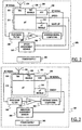
- a fixed wireless sensor node 105 i (i is an index taking values between 1 and N ) of the WSN 100 is schematically shown, in terms of the functional blocks relevant to the understanding of the invention embodiment to be described.
- the fixed sensor node 105 i includes a WSN unit 205, for example, albeit not limitatively, an Integrated Circuit (IC) chip in which a microcontroller ( ⁇ C) 210 and a ⁇ C enable module 215 are integrated.
- the WSN unit 205 includes a ZigBee transceiver (TRX) 220 and a TRX enable module 225, and an Analog-to-Digital Converter (ADC) 230 (in alternative embodiments of the invention, one or more of the ⁇ C 210, the ( ⁇ C enable module 215, the TRX 220, the TRX enable module 225, and the ADC 230 may be discrete components, instead of being integrated on a same chip).
- TRX ZigBee transceiver
- ADC Analog-to-Digital Converter
- the TRX 220 is coupled to an antenna 235 for the reception and the transmission of radio frequency (RF) analog signals.
- the antenna 235 is connected to a filter 240, particularly a pass band filter of the fixed wireless sensor node 105 1 , for example a filter having a pass band centered around about 2.4 GHz, for filtering the received RF signal;
- the output of the filter 240 is coupled to a Low-Noise Amplifier (LNA) 245.
- LNA Low-Noise Amplifier
- the output of the LNA 245 is coupled to an average signal computing module 250, adapted to evaluate an average power value of the received, filtered and amplified RF signal.
- the output of the average signal computing module 250 is coupled to the ADC 230.
- the fixed sensor node 105 l further includes a speed assessment sensor 255, adapted to detect the speed of the vehicle 115 entering the area where the WSN 100 is deployed.
- the speed assessment sensor 255 for example, exploits the Doppler effect, by means of a microwave detector for estimating the speed of the vehicle 115 in module and direction.
- the speed assessment sensor 255 is adapted to provide to the microcontroller 210 data denoted in the drawing by the reference SPEED which correspond to the estimated vehicle speed, and also to provide a wake-up signal WAKE-UP to the microcontroller enable module 215, adapted to wake the microcontroller up (the wake-up signal WAKE-UP may for example be provided to an interrupt input of the microcontroller).
- the speed assessment sensor 255 need not be present on every fixed sensor node, being sufficient that it is provided in the first fixed sensor node of the WSN 100 that a vehicle meets when it enters the area covered by the WSN 100 moving along the highway 110, such as the fixed sensor node 105 1 .
- the speed assessment sensor might be a component external to the fixed sensor node 105 i , being coupled to it for providing the indication of the estimated vehicle speed, and the wake-up signal.
- a power supply 260 for example a battery (e.g ., a couple of AAA batteries) supplies the fixed sensor node 105 i ; particularly, the power supply 260 supplies the speed assessment sensor 255 and the WSN chip 205.
- a battery e.g ., a couple of AAA batteries
- the mobile sensor node 120 includes a WSN unit 305, for example an IC chip where a ⁇ C 310 and a ⁇ C enable module 315 are integrated, together with a ZigBee TRX 320, a TRX enable module 325 and an ADC 330.
- a WSN unit 305 for example an IC chip where a ⁇ C 310 and a ⁇ C enable module 315 are integrated, together with a ZigBee TRX 320, a TRX enable module 325 and an ADC 330.
- the TRX 320 is coupled to an antenna 335 for the reception and the transmission of RF signals; the antenna 335 is connected to a filter 340, particularly a pass band filter (similar to the pass band filter 240 in the fixed sensor node) for filtering the received RF signal.
- the output of the filter 340 is coupled to an LNA 345 adapted to amplify the filtered RF signal.
- the output of the LNA 345 is coupled to an average signal computing module 350, adapted to evaluate the average power value of the received, filtered and amplified RF signal.
- the output of the average signal computing module 350 is coupled to the ADC 330.
- the mobile sensor node 120 further includes a vibration assessment sensor 355, adapted to detect the activity status of the vehicle 115 carrying the mobile sensor node 120; in detail, the vibration assessment sensor 355 is adapted to analyse the vibrations of the vehicle 115, for example by means of an accelerometer, so as to establish if the vehicle is moving or not.
- the vibration sensor 355 provides an on/off signal ON/OFF to the ⁇ C enable module 315 in accordance with the estimated vibrations of the vehicle 115, so as to enable the turning of the ⁇ C 310 on (if the vehicle is moving) or off (if the vehicle is steady).
- a power supply 360 supplies the mobile sensor node 120, for example, a battery power supply (e.g. , a couple of AAA batteries, as in the fixed sensor node 105 i ); particularly, the power supply 360 supplies the vibration assessment sensor 355 and the WSN unit 305.
- a battery power supply e.g. , a couple of AAA batteries, as in the fixed sensor node 105 i .
- FIG 4 schematically illustrates protocol layer stacks 405 and 410 implemented in a generic fixed sensor node 105 i , structured according the Open System Interconnection (OSI) architecture.
- OSI Open System Interconnection
- the OSI architecture divides functions of a protocol into a series of layers; typically, each layer has the property that it only uses the functions of the layer below, and only exports functionality to the layer above (each layer performs services for the next higher layer and makes requests of the next lower layer).
- the sensor node 105 i is structured in a layered fashion to enable the use of standard tools and to facilitate the design of the WSN from network connections to interoperation with the remote database accessed through an external distribution network.
- the protocol layer stack 405 is responsible of the sensing functions, and includes a sensor layer 415 and a sensing management layer 420; the protocol layer stack 405 manages the operation of the speed assessment sensor 255 included in (or coupled to) the respective fixed sensor node 105; for the detection of the speed of vehicles running along the highway.
- the protocol layer stack 410 is responsible of managing the telecommunication (TLC) functions, and manages the wireless communication with the other fixed sensor nodes 105 i of the WSN 100 and with the mobile sensor node 120.
- the protocol layer stack 410 includes an application layer 425, an Application Program Interface (API) layer 430 coupled to the sensing management layer 420 of the protocol layer stack 405, a network layer 435, a Media Access Control (MAC) layer 440 and a physical (PHY) layer 445 (that defines all the electrical and physical specifications for the communications).
- API Application Program Interface
- MAC Media Access Control
- PHY physical
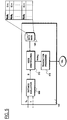
- the service center 135 is schematically shown, in terms of the functional blocks relevant to the understanding of the invention embodiment to be described (in Figure 5 the billing processing 150 is omitted, for the sake of simplicity).
- the service center 135 includes a distance evaluation module 505 adapted to receive from the fixed sensor nodes of the WSN 100, particularly from the fixed sensor node 105 1 , the average speed value v m of a vehicle, estimated by the speed assessment sensor 255 when the vehicle enters the area covered by the WSN 100.
- the services offered by the service center 135 may relate to a single type of transaction, or to two or more transaction types; in the former case, the transaction to be carried out in respect of the vehicle entering the area covered by the WSN 100 is known a priori by the service center 135; if instead more than one transaction type is supported, the service center (e.g ., the distance evaluation module 505 ) receives also an indication of the transaction type T, communicated by the mobile sensor node 120 to the fixed sensor node 105 1 .
- the distance evaluation module 505 estimates a distance D covered by the vehicle 115 during the transaction processing; the estimated distance D is provided to a node identification module 510 of the service center 135.
- the node identification module 510 has access to the database 145, where the configuration of the WSN 100 is stored; in particular, each node address Node 1 - Node N , being the network address that identifies a respective fixed sensor node 105 1 - 105 N , is associated to a respective position indication that indicates the position of that sensor node in the WSN 100, e.g . the position along the highway access ramp 110.
- the fixed sensor node 105 1 has position identified by a distance of 0 m, the fixed sensor node 105 2 by a distance of 10 m from fixed sensor node 105 1 , the fixed sensor node 105 7 by a distance of 40 m from fixed sensor node 105 1 , etc.
- the node identification module 510 is adapted to identify an address Node tgt of the target fixed sensor node 105 x which is the sensor node selected for completing the transaction with the mobile sensor node 120.
- a transaction processing module 515 of the service center 135 is adapted to process the data required for the transaction and to transmit them to the selected, target fixed sensor node 105x.
- the distance evaluation module 505 exploits an estimated time duration T of the transaction T to be carried out, an estimated time ⁇ t required for accessing the distribution network 130 and the service center 135, and the estimated speed v m of the vehicle 115.
- the node identification module 510 is capable of forecasting the position of the vehicle 115 at the time the transaction shall be completed, and thus determining the target fixed sensor node 105x in accordance with the respective position along the highway access ramp 110.
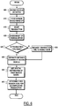
- Figure 6 is a schematic flowchart describing a transaction procedure, according to an embodiment of the present invention, performed by the WSN 100.
- the speed assessment sensor 255 estimates the speed of the vehicle 115, and asserts the wake-up signal WAKE-UP (block 610 ): the microcontroller 210 is thus woken up.
- the microcontroller 210 further receives the indication SPEED of the estimated average vehicle speed value.
- the microcontroller 210 assesses whether the estimated average vehicle speed exceeds a predetermined speed threshold value: if the average speed value is higher than the threshold speed value, then the fixed sensor node 105 1 understands that a vehicle is entering the WSN 100 area, and that the whole WSN 100 has to be enabled for a transaction.
- the transceiver 220 of the fixed sensor node 105 1 is consequently enabled and starts sending wake-up commands to the other fixed sensor nodes of the WSN 100.
- the wake-up commands may be in the form of beacon signals, that the fixed node 105 1 broadcasts to the other nodes of the WSN 100.
- the beacon signals that the fixed sensor node 105 1 broadcasts allows waking-up, enabling both the mobile sensor node 120, carried by the detected vehicle 115, and all the other fixed sensor nodes 105 2 - 105 N .
- the beacon signals are received by the fixed sensor nodes 105 2 and 105 3 and the mobile sensor node 120 which are in the radio range of the fixed sensor node 105 1 ; the TRX enable modules 225 in the fixed sensor nodes 105 2 and 105 3 and 325 in the mobile sensor node 120 assess if the average power of the received beacon signal exceeds a prescribed, minimum threshold value, then the transceivers 220, 320 are enabled.
- the first fixed sensor node 105 1 assigns thereto a respective network address and, accordingly, the mobile sensor node 120 is "locked" by the WSN 100.
- a transaction such as a toll collection, starts (block 615 ) and, according to the present invention, in the following steps of the transaction procedure the fixed sensor node 105 1 - 105 N that will have to accomplish the transaction is individuated, for example by the service center 135, as described above in connection with Figure 5 .
- the fixed sensor node 105 1 provides to the service center 135 the estimated average speed of the vehicle 115 (block 620 ); this is done by a multi-hop routing through the fixed sensor nodes 105 2 -105 6 to the gateway node 125, and then through the distribution network 130.
- the service center 135 receives also this information (if this information is not automatically provided by the mobile node, the service center may request it - block 630 ). After receiving the indication of the transaction type, the service center 135 determines the corresponding estimated transaction time T (if the transaction type is fixed, the transaction procedure moves directly to the block 635, because the transaction time T is known a priori ).
- the service center 135 exploits the transaction time T, the access time ⁇ t and the estimated average speed value v m for estimating the distance D covered by the vehicle 115 during the accomplishment of the transaction (block 635 ).
- the service center 135 also reads from the database 145 the data regarding the distribution of the fixed nodes in the area covered by the WSN 100 (block 640 ).
- the service center 135 determines the target fixed sensor node 105 x that will have to complete the transaction with the mobile sensor node 120 and transmits thereto the data necessary for completing the transaction, through the distribution network 130, the gateway node 125 and a multi-hop routing accomplished by the other fixed sensor nodes (block 645 ).
- the toll collection is accomplished by charging, for example, a credit card account of the driver of the vehicle 115.
- the gateway node 125 In case the fixed nodes 105 1 - 105 N detect an irregularity, such as the entrance into the WSN 100 area of a vehicle without a sensor node, the gateway node 125, an Optical Character Recognition (OCR) system (not shown in the drawing) may be provided for, adapted to detect a number plate of the vehicle. The number plate is then communicated to the service center 135, so as to successively identifying the vehicle owner and taking the necessary steps for billing the toll thereto.
- OCR Optical Character Recognition
- the WSN 100 is able to perform a transaction with a mobile sensor node 120 without the use of any gate, because it is not necessary to have the vehicle slow down and, possibly, stop.
- the WSN 100 interacts with the mobile sensor node 120 and accomplishes the transaction despite of the speed of the vehicle 115 within the radio coverage area of the WSN 100.
- tollgates typically installed at entrances and exits of highways and closed parking areas may be eliminated. This allows avoiding the related set-up and maintenance costs, as well as the slowing of the traffic.
- the vibration assessment sensor 355 continuously assess the level of vibrations, and waits for a movement of the vehicle 115 to be detected (block 705, and decision block 710, exit branch N ). When a movement is detected (block 710, exit branch Y ), then by asserting the on/off signal ON/OFF vibration assessment sensor 355 enables the microcontroller 310 (block 715 ).
- the TRX enable module 325 waits for receiving RF signals from the fixed sensor nodes (block 720 ); in detail, any detected RF signal is filtered by the pass band filter 340 and amplified by the LNA 345 and, successively, the average signal computing module 350 evaluates its average power value, feeding it to the TRX enable module 325.
- the TRX enable module 325 assesses whether the average power value of the RF signal is higher than a prescribed minimum threshold, meaning that the mobile sensor node is within an area covered by a WSN (block 725 ); in the negative case, the mobile sensor node 120 waits for receiving a valid RF signal, otherwise, if the average power value of the RF signal is higher than the threshold value, the TRX enable module 325 enables the TRX 320 (block 730 ).
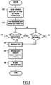
- Figure 8 shows a schematic flowchart describing a wake-up fixed sensor node procedure.
- the WSN 100 is formed (after the sensor nodes have been positioned and have been powered up), and each fixed sensor node 105 1 - 105 N acquires automatically a respective network address within the WSN 100 (block 805 ).
- the microcontroller 210 of each fixed sensor node 105 i puts the sensor node, particularly the transceiver 220 in sleep mode (block 810 ).
- the generic fixed sensor node 105 i waits until a movement is detected by the speed assessment sensor 255 (block 815 ), if the considered sensor node is equipped with or coupled to it, like in the case of the fixed sensor node 105 1 . In case a detected average speed value is lower than a threshold speed value, or in case the fixed sensor node 105 i is not equipped with or coupled to the speed assessment sensor 255, the fixed sensor node 105 i tests if any RF signal is received (block 820 ).
- a received RF signal is filtered by the pass band filter 240, amplified by the LNA 245 and, successively, the average signal computing module 250 evaluates its average power value and provides it to the TRX enable module 235.
- the TRX enable module 235 compares the calculated average power value of the RF signal to a threshold value: if the average power value of the received RF signal is lower than the threshold, the fixed sensor node 105 1 waits until a moving vehicle is assessed, or a valid RF signal is received. If the average power value of the RF signal exceeds the threshold value, then TRX 220 is enabled (block 825 ).
- the fixed sensor node 105 i After the TRX 220 is enabled, the fixed sensor node 105 i starts broadcasting beacon signals (block 830 ), i.e . it generates or propagates the wake-up wave that wakes up the other fixed sensor nodes 105 i .
- an application is started (block 835 ) for performing the transaction with the mobile sensor node 120 on the vehicle 115.
- the wake-up procedures according to the described embodiment of the present invention allows greatly reducing a power consumption of the mobile and fixed sensor nodes of the WSN, by enabling the microcontrollers and the transceivers only when required.
- the microcontroller of the mobile sensor nodes needs to be enabled only when a vehicle carrying it is moving, and the transceiver of the mobile sensor node needs to be enabled only when a RF signal is sensed.
- the microcontroller of the fixed sensor nodes needs to be enabled only when a movement is detected or an RF signal is received. If the mobile and fixed sensor nodes sense an RF signal, then the microcontrollers enable also the transceiver, which in the opposite case are kept turned off.
- the WSN is energy-efficient, because the microcontrollers and the transceivers are kept off most of the time, and this allows overcoming a problem of power consumption that typically affect sensor networks known in art, especially multi-hop sensor networks, where the nodes act also as routers.
- a WSN 900 according to another embodiment of the present invention is shown; particularly, the WSN 900 is exploited for a pollution monitoring and a cross-reference to car numbers, for example, in a urban area 902 (in the drawing, reference numerals like those used in Figure 1 denote same or similar elements).
- the WSN 900 includes a plurality of fixed sensor nodes 905 arranged within the urban area 902 and along a plurality of roads 910 accessing the urban area 902. Vehicles 915 running along the roads 910 and equipped with respective mobile sensor nodes 920, are "locked" by the WSN 900 when they enter in an area covered by the RF signals provided by the fixed sensor nodes 905, in the same way as in the previously described embodiment.
- gateway node 925 for communicating with a distribution network 930 in turn coupled to a service center (not shown in the drawing) that is adapted to process the data collected by the fixed sensor nodes 905. Also, within the urban area 902 some fixed sensor nodes operate as gateway nodes 925 for communicating with the distribution network 930.
- the WSN 900 allows counting the number of vehicles 915 that are within the urban area 902 and, accordingly, to evaluate the pollution versus the numbers of vehicles 915, as shown in a graph included in Figure 9 .
- the WSN 900 "locks" the respective mobile sensor node 920.
- the fixed sensor node 905, detecting the presence the mobile sensor node 920, communicates the information to the nearest gateway node 925, by a multi-hop routing; the gateway node 925 in turn provides the information to the service center through the distribution network 930, for the data processing.
- the fixed sensor nodes 905 signal to the service center when a vehicle 915 leaves the urban area 902 or when the vehicle 915 stops within the urban area 902, for example, by parking or because it is a car of a resident of the urban area 902.
- the sensor nodes could be compliant to a communication standard different from the described ZigBeeTM standard.
- the area covered by the sensor network might be different from a highway or a urban area, and the mobile sensor nodes are not necessarily mounted on vehicles.
- the architecture of the mobile and fixed sensor nodes might be different and, particularly, the sensor nodes might include other modules with different functions.
- the sensor network might also be or include wireline connections between the sensor nodes. The same network can perform a plurality of types of transactions and can be exploited for a number of applications simultaneously.
- the service center can include more than one data base and more than one transaction processing module; furthermore, the transaction processing module can be included in, or directly coupled to, one of the sensor nodes.
Landscapes
- Engineering & Computer Science (AREA)
- Health & Medical Sciences (AREA)
- Computing Systems (AREA)
- General Health & Medical Sciences (AREA)
- Medical Informatics (AREA)
- Computer Networks & Wireless Communication (AREA)
- Signal Processing (AREA)
- Mobile Radio Communication Systems (AREA)
- Traffic Control Systems (AREA)
Claims (10)
- System (100, 130, 135; 900, 930) umfassend:- mehrere vernetzte Knoten (1051 -105N; 905), die innerhalb eines überwachten Bereichs (110; 902) räumlich verteilt sind und dafür eingerichtet sind, mit einer mobilen Einheit (115, 120; 915, 920) zu interagieren, die in den Bereich eintritt und sich durch diesen bewegt, wobei die mehreren Knoten wenigstens einen Bereichseintrittsknoten (1051), der dafür eingerichtet ist, die mobile Einheit beim Eintritt in den überwachten Bereich zu detektieren (605), und einen Transaktionsknoten (1057) zum Ausführen einer Transaktion mit der mobilen Einheit umfasst, umfassend:- ein entferntes Transaktionsverarbeitungszentrum (135), das von den mehreren vernetzten Knoten entfernt ist und durch ein Kommunikationsnetzwerk (130) und einen Netzübergangsknoten (125) der mehreren vernetzten Knoten in Kommunikationsbeziehung mit den Knoten steht, wobei das Transaktionsverarbeitungszentrum zum Verarbeiten (620, 625, 630, 635, 640, 645) von Daten zur Transaktion und zum Bereitstellen der Daten an den Transaktionsknoten erforderlich ist,wobei das Transaktionszentrum umfasst:eine Knotenauswahleinheit (505, 510), die dafür eingerichtet ist, den Transaktionsknoten unter den mehreren Knoten basierend auf einer Schätzung der Bewegungsgeschwindigkeit der mobilen Einheit und auf einer Kenntnis einer räumlichen Verteilung der Knoten innerhalb des überwachten Bereichs dynamisch auszuwählen (620, 625, 630, 635, 640, 645), wobei die Kenntnis einer räumlichen Verteilung eine Kenntnis der jeweiligen Positionsangabe umfasst, welche die Positionen der Sensorknoten angibt, wobei die Knotenauswahleinheit beinhaltet:eine Transaktionszeit-Schätzungseinheit (505), die dafür eingerichtet ist, eine Transaktionszeit, die zum Verarbeiten der Daten notwendig ist, zu schätzen (625, 630, 635);eine Distanzschätzungseinheit (505), die dafür eingerichtet ist, basierend auf einer Schätzung der Bewegungsgeschwindigkeit der mobilen Einheit, die bei der Detektion der mobilen Einheit beim Eintritt in den überwachten Bereich erfolgt, eine Distanz, die durch die mobile Einheit innerhalb des Bereichs in der Transaktionszeit abgedeckt wird, zu schätzen (640, 645); undeine Knotenidentifikationseinheit (510), die dafür eingerichtet ist, den Transaktionsknoten basierend auf der geschätzten Distanz auszuwählen (645).
- System nach Anspruch 1, wobei der Eintrittsknoten operativ mit einem Geschwindigkeitsbeurteilungssensor (255) gekoppelt ist, der dafür eingerichtet ist, die Bewegungsgeschwindigkeit der mobilen Einheit innerhalb des Bereichs zu schätzen.
- System nach einem der Ansprüche 1 bis 2, wobei die Knoten drahtlose Knoten sind, die jeweils einen drahtlosen Sende-Empfänger (220) beinhalten.
- System nach einem der vorhergehenden Ansprüche, wobei die Knoten an jeweiligen feststehenden Positionen innerhalb des Bereichs räumlich verteilt sind.
- System nach einem der vorhergehenden Ansprüche, wobei jeder Knoten dafür eingerichtet ist, in einen Zustand des niedrigen Leistungsverbrauchs einzutreten, wenn er außer Betrieb ist, und wobei der Eintrittsknoten dafür eingerichtet ist, aus dem Zustand des niedrigen Leistungsverbrauchs aufzuwachen, wenn detektiert wird, dass die mobile Einheit in den überwachten Bereich eintritt.
- System nach einem der vorhergehenden Ansprüche, wobei die mobile Einheit eine der mehreren vernetzten Knoten ist.
- System nach Anspruch 6, wobei die mobile Einheit einen Vibrationssensor umfasst, der dafür eingerichtet ist, die mobile Einheit zu aktivieren, wenn eine Vibration beurteilt wird.
- System nach Anspruch 6 oder 7, wobei die mobile Einheit eine Kommunikationseinheit umfasst, die dafür eingerichtet ist, aufzuwachen, wenn die mobile Einheit in den überwachten Bereich eintritt.
- Verfahren zum Betreiben eines Netzwerks (100; 900) aus mehreren Knoten (1051 - 105N; 905) die innerhalb eines überwachten Bereichs (110; 902) räumlich verteilt sind und dafür eingerichtet sind, mit einer mobilen Einheit (115, 120; 915, 920) zu interagieren, die in den überwachten Bereich eintritt, um eine Transaktion auszuführen, wobei das Verfahren beinhaltet:Veranlassen, dass wenigstens ein Eintrittsknoten (1051) der mehreren Knoten das Eintreten der mobilen Einheit in den überwachten Bereich detektiert (605);Veranlassen, dass der wenigstens eine Eintrittsknoten eine Bewegungsgeschwindigkeit der mobilen Einheit schätzt;Veranlassen, dass der wenigstens eine Eintrittsknoten die geschätzte Bewegungsgeschwindigkeit an ein entferntes Transaktionsverarbeitungszentrum (135) bereitstellt, das von den mehreren vernetzten Knoten entfernt ist und durch ein Kommunikationsnetzwerk (130) und einen Netzübergangsknoten (125) der vernetzten Knoten in Kommunikationsbeziehung mit den mehreren Knoten steht,Veranlassen, dass das Transaktionsverarbeitungszentrumeine zum Ausführen der Transaktion erforderliche Transaktionszeit schätzt (625, 630, 635);basierend auf einer Schätzung der Bewegungsgeschwindigkeit der mobilen Einheit, die bei der Detektion der mobilen Einheit beim Eintritt in den überwachten Bereich erfolgt, eine Distanz schätzt (640, 645), die durch die mobile Einheit innerhalb des überwachten Bereichs in der geschätzten Transaktionszeit zurückgelegt wird; undbasierend auf der geschätzten Distanz und auf einer Kenntnis einer räumlichen Verteilung der Knoten innerhalb des überwachten Bereichs einen Transaktionsabschlussknoten unter den mehreren Knoten dynamisch auswählt (645), wobei die Kenntnis einer räumlichen Verteilung eine Kenntnis der jeweiligen Positionsangabe umfasst, welche die Positionen der Sensorknoten angibt.
- Verfahren nach Anspruch 9, wobei das Schätzen der Transaktionszeit beinhaltet:- Erhalten von der mobilen Einheit eine Angabe eines Typs der auszuführenden Transaktion, und- dynamisches Schätzen der Transaktionszeit basierend auf der Transaktionstypangabe.
Applications Claiming Priority (1)
| Application Number | Priority Date | Filing Date | Title |
|---|---|---|---|
| PCT/EP2006/011987 WO2008071209A1 (en) | 2006-12-13 | 2006-12-13 | Sensor network |
Publications (2)
| Publication Number | Publication Date |
|---|---|
| EP2095579A1 EP2095579A1 (de) | 2009-09-02 |
| EP2095579B1 true EP2095579B1 (de) | 2018-11-07 |
Family
ID=38346150
Family Applications (1)
| Application Number | Title | Priority Date | Filing Date |
|---|---|---|---|
| EP06829563.3A Not-in-force EP2095579B1 (de) | 2006-12-13 | 2006-12-13 | Sensornetzwerk |
Country Status (3)
| Country | Link |
|---|---|
| US (1) | US8321171B2 (de) |
| EP (1) | EP2095579B1 (de) |
| WO (1) | WO2008071209A1 (de) |
Families Citing this family (21)
| Publication number | Priority date | Publication date | Assignee | Title |
|---|---|---|---|---|
| US20110037618A1 (en) * | 2009-08-11 | 2011-02-17 | Ginsberg Matthew L | Driver Safety System Using Machine Learning |
| US9852624B2 (en) | 2007-09-07 | 2017-12-26 | Connected Signals, Inc. | Network security system with application for driver safety system |
| US10083607B2 (en) | 2007-09-07 | 2018-09-25 | Green Driver, Inc. | Driver safety enhancement using intelligent traffic signals and GPS |
| US9043138B2 (en) * | 2007-09-07 | 2015-05-26 | Green Driver, Inc. | System and method for automated updating of map information |
| US20110037619A1 (en) * | 2009-08-11 | 2011-02-17 | On Time Systems, Inc. | Traffic Routing Using Intelligent Traffic Signals, GPS and Mobile Data Devices |
| US8280362B2 (en) * | 2008-05-28 | 2012-10-02 | West Corporation | System and method for controlling a feature of a mobile communication unit |
| JP5309816B2 (ja) * | 2008-09-09 | 2013-10-09 | 富士通株式会社 | データ管理プログラム、データ管理装置、およびデータ管理方法 |
| EP2417827A4 (de) * | 2009-04-07 | 2014-03-05 | Ericsson Telefon Ab L M | Anschliessen eines sensors an ein wsan |
| US10198942B2 (en) | 2009-08-11 | 2019-02-05 | Connected Signals, Inc. | Traffic routing display system with multiple signal lookahead |
| US8849926B2 (en) * | 2010-08-06 | 2014-09-30 | Simon Fraser University | System and method for self-calibrating, self-organizing and localizing sensors in wireless sensor networks |
| JP5104937B2 (ja) * | 2010-11-30 | 2012-12-19 | 富士ゼロックス株式会社 | 電力供給制御装置、画像処理装置、電力供給制御プログラム |
| US8423064B2 (en) * | 2011-05-20 | 2013-04-16 | Google Inc. | Distributed blind source separation |
| WO2013186640A2 (en) | 2012-05-24 | 2013-12-19 | Lundy Douglas H | Threat detection system and method |
| US20150363769A1 (en) * | 2014-06-16 | 2015-12-17 | Bank Of America Corporation | Cryptocurrency Real-Time Conversion System |
| KR20170023085A (ko) | 2014-06-18 | 2017-03-02 | 센시티 시스템즈 아이엔씨. | 인터액티브 광 센서 네트워크들을 위한 애플리케이션 프레임워크 |
| US9426616B1 (en) * | 2015-02-10 | 2016-08-23 | Tyco Fire & Security Gmbh | Wireless sensor network controlled low energy link |
| JP2016184855A (ja) * | 2015-03-26 | 2016-10-20 | 三菱電機株式会社 | 移動目標攻撃装置 |
| US10194264B2 (en) * | 2015-09-22 | 2019-01-29 | Veniam, Inc. | Systems and methods for collecting sensor data in a network of moving things |
| US11362882B2 (en) * | 2017-08-25 | 2022-06-14 | Veniam, Inc. | Methods and systems for optimal and adaptive urban scanning using self-organized fleets of autonomous vehicles |
| US11452038B2 (en) * | 2018-02-23 | 2022-09-20 | Agsensio Pty Ltd | Power conserving local wireless network |
| CN113464849A (zh) * | 2021-06-10 | 2021-10-01 | 昆明理工大学 | 一种基于ZigBee与多跳路由的矿浆管道位移故障检测系统 |
Family Cites Families (12)
| Publication number | Priority date | Publication date | Assignee | Title |
|---|---|---|---|---|
| JP3141933B2 (ja) | 1997-09-05 | 2001-03-07 | 株式会社デンソー | 自動料金収受システム |
| CA2381362C (en) * | 1999-08-11 | 2013-08-06 | Mark Iv Industries Limited | Method and means for rf toll collection |
| WO2001026335A2 (en) | 1999-10-06 | 2001-04-12 | Sensoria Corporation | Distributed signal processing in a network |
| US7484008B1 (en) * | 1999-10-06 | 2009-01-27 | Borgia/Cummins, Llc | Apparatus for vehicle internetworks |
| GB0228807D0 (en) | 2002-12-11 | 2003-01-15 | Koninkl Philips Electronics Nv | Opportunistic location tracking |
| JP4258225B2 (ja) * | 2003-02-14 | 2009-04-30 | トヨタ自動車株式会社 | 車両の位置検出装置及び方法 |
| EP1464988B1 (de) | 2003-04-03 | 2008-06-11 | Mitsubishi Electric Information Technology Centre Europe B.V. | Laufzeitdifferenzbestimmung in verteilten Sensornetzwerken |
| US7688222B2 (en) | 2003-09-18 | 2010-03-30 | Spot Devices, Inc. | Methods, systems and devices related to road mounted indicators for providing visual indications to approaching traffic |
| US7720993B2 (en) * | 2003-12-17 | 2010-05-18 | Palo Alto Research Center Incorporated | Information driven routing in ad hoc sensor networks |
| US7383053B2 (en) | 2004-04-28 | 2008-06-03 | Lawrence Livermore National Security, Llc | Position estimation of transceivers in communication networks |
| US7372773B2 (en) * | 2005-04-08 | 2008-05-13 | Honeywell International, Inc. | Method and system of providing clustered networks of bearing-measuring sensors |
| EP1713206A1 (de) * | 2005-04-11 | 2006-10-18 | Last Mile Communications/Tivis Limited | Ein verteiltes Kommunikationsnetzwerk mit drahtlos verbundenen Funkfeststationen |
-
2006
- 2006-12-13 EP EP06829563.3A patent/EP2095579B1/de not_active Not-in-force
- 2006-12-13 WO PCT/EP2006/011987 patent/WO2008071209A1/en not_active Ceased
- 2006-12-13 US US12/448,200 patent/US8321171B2/en not_active Expired - Fee Related
Non-Patent Citations (1)
| Title |
|---|
| None * |
Also Published As
| Publication number | Publication date |
|---|---|
| US20100094583A1 (en) | 2010-04-15 |
| US8321171B2 (en) | 2012-11-27 |
| EP2095579A1 (de) | 2009-09-02 |
| WO2008071209A1 (en) | 2008-06-19 |
Similar Documents
| Publication | Publication Date | Title |
|---|---|---|
| EP2095579B1 (de) | Sensornetzwerk | |
| US7016311B2 (en) | Multiple protocol transponder | |
| US7714742B1 (en) | Wireless mesh network parking measurement system | |
| US9154982B2 (en) | Method and system for a traffic management network | |
| CN103198528B (zh) | 基于rssi定位的停车场收费方法 | |
| EP2831860B1 (de) | System und verfahren zur verkehrsverwaltung mit beleuchtungsnetzwerken | |
| US20070276600A1 (en) | Intersection collision warning system | |
| US20110298603A1 (en) | Intersection Collision Warning System | |
| US20040142685A1 (en) | Wireless vending communication systems | |
| Ahmad et al. | Internet of things‐aided intelligent transport systems in smart cities: Challenges, opportunities, and future | |
| EP2171691B1 (de) | Verfahren und system zum detektieren eines sich bewegenden fahrzeugs in einem vorbestimmten bereich | |
| KR101773515B1 (ko) | 블루투스-와이파이 센서 기반의 스마트 교통제어 시스템 및 그 방법 | |
| KR101038946B1 (ko) | Usn을 이용한 교통정보 수집 및 처리 시스템 및 그 방법 | |
| KR20020045581A (ko) | Dsrc를 이용한 주차 요금 정산 시스템 | |
| CN102426788A (zh) | 基于ZigBee技术的高速公路无线测速系统 | |
| CN107507419A (zh) | 一种基于wifi信号的交通流量检测器 | |
| CN102968824A (zh) | 基于光通信的车辆管理系统 | |
| CN114120460A (zh) | 一种融合etc和v2x功能的智能车载终端obu及应用 | |
| CN103078686A (zh) | 用于降低etc系统中邻道干扰的方法、系统及装置 | |
| Sung et al. | Collision warning system on a curved road using wireless sensor networks | |
| KR100761068B1 (ko) | 광대역 임펄스를 이용한 교통정보 수집/관리 장치 및 그방법과 그를 이용한 신호등 제어 시스템 및 그 방법 | |
| KR100991254B1 (ko) | 무선센서 네트워크 기반의 액티브 태그를 이용한주차관리시스템 및 그 방법 | |
| CN111899518A (zh) | 一种基于物联网的电单车违章管理系统 | |
| JP3405223B2 (ja) | 自動料金収受用路側システム | |
| CN112085876B (zh) | 一种人员进出管理方法、系统及分体式车载设备 |
Legal Events
| Date | Code | Title | Description |
|---|---|---|---|
| PUAI | Public reference made under article 153(3) epc to a published international application that has entered the european phase |
Free format text: ORIGINAL CODE: 0009012 |
|
| 17P | Request for examination filed |
Effective date: 20090619 |
|
| AK | Designated contracting states |
Kind code of ref document: A1 Designated state(s): AT BE BG CH CY CZ DE DK EE ES FI FR GB GR HU IE IS IT LI LT LU LV MC NL PL PT RO SE SI SK TR |
|
| DAX | Request for extension of the european patent (deleted) | ||
| RAP1 | Party data changed (applicant data changed or rights of an application transferred) |
Owner name: TELECOM ITALIA S.P.A. |
|
| 17Q | First examination report despatched |
Effective date: 20150602 |
|
| REG | Reference to a national code |
Ref country code: DE Ref legal event code: R079 Ref document number: 602006056792 Country of ref document: DE Free format text: PREVIOUS MAIN CLASS: H04L0012560000 Ipc: H04L0029080000 |
|
| RIC1 | Information provided on ipc code assigned before grant |
Ipc: H04L 29/08 20060101AFI20180425BHEP Ipc: H04W 84/18 20090101ALN20180425BHEP |
|
| GRAP | Despatch of communication of intention to grant a patent |
Free format text: ORIGINAL CODE: EPIDOSNIGR1 |
|
| RIC1 | Information provided on ipc code assigned before grant |
Ipc: H04L 29/08 20060101AFI20180517BHEP Ipc: H04W 84/18 20090101ALN20180517BHEP |
|
| INTG | Intention to grant announced |
Effective date: 20180604 |
|
| GRAS | Grant fee paid |
Free format text: ORIGINAL CODE: EPIDOSNIGR3 |
|
| GRAA | (expected) grant |
Free format text: ORIGINAL CODE: 0009210 |
|
| AK | Designated contracting states |
Kind code of ref document: B1 Designated state(s): AT BE BG CH CY CZ DE DK EE ES FI FR GB GR HU IE IS IT LI LT LU LV MC NL PL PT RO SE SI SK TR |
|
| REG | Reference to a national code |
Ref country code: GB Ref legal event code: FG4D |
|
| REG | Reference to a national code |
Ref country code: CH Ref legal event code: EP Ref country code: AT Ref legal event code: REF Ref document number: 1063447 Country of ref document: AT Kind code of ref document: T Effective date: 20181115 |
|
| REG | Reference to a national code |
Ref country code: IE Ref legal event code: FG4D |
|
| REG | Reference to a national code |
Ref country code: DE Ref legal event code: R096 Ref document number: 602006056792 Country of ref document: DE |
|
| REG | Reference to a national code |
Ref country code: NL Ref legal event code: MP Effective date: 20181107 |
|
| REG | Reference to a national code |
Ref country code: LT Ref legal event code: MG4D |
|
| REG | Reference to a national code |
Ref country code: AT Ref legal event code: MK05 Ref document number: 1063447 Country of ref document: AT Kind code of ref document: T Effective date: 20181107 |
|
| PG25 | Lapsed in a contracting state [announced via postgrant information from national office to epo] |
Ref country code: ES Free format text: LAPSE BECAUSE OF FAILURE TO SUBMIT A TRANSLATION OF THE DESCRIPTION OR TO PAY THE FEE WITHIN THE PRESCRIBED TIME-LIMIT Effective date: 20181107 Ref country code: LV Free format text: LAPSE BECAUSE OF FAILURE TO SUBMIT A TRANSLATION OF THE DESCRIPTION OR TO PAY THE FEE WITHIN THE PRESCRIBED TIME-LIMIT Effective date: 20181107 Ref country code: AT Free format text: LAPSE BECAUSE OF FAILURE TO SUBMIT A TRANSLATION OF THE DESCRIPTION OR TO PAY THE FEE WITHIN THE PRESCRIBED TIME-LIMIT Effective date: 20181107 Ref country code: IS Free format text: LAPSE BECAUSE OF FAILURE TO SUBMIT A TRANSLATION OF THE DESCRIPTION OR TO PAY THE FEE WITHIN THE PRESCRIBED TIME-LIMIT Effective date: 20190307 Ref country code: FI Free format text: LAPSE BECAUSE OF FAILURE TO SUBMIT A TRANSLATION OF THE DESCRIPTION OR TO PAY THE FEE WITHIN THE PRESCRIBED TIME-LIMIT Effective date: 20181107 Ref country code: LT Free format text: LAPSE BECAUSE OF FAILURE TO SUBMIT A TRANSLATION OF THE DESCRIPTION OR TO PAY THE FEE WITHIN THE PRESCRIBED TIME-LIMIT Effective date: 20181107 Ref country code: BG Free format text: LAPSE BECAUSE OF FAILURE TO SUBMIT A TRANSLATION OF THE DESCRIPTION OR TO PAY THE FEE WITHIN THE PRESCRIBED TIME-LIMIT Effective date: 20190207 |
|
| PG25 | Lapsed in a contracting state [announced via postgrant information from national office to epo] |
Ref country code: NL Free format text: LAPSE BECAUSE OF FAILURE TO SUBMIT A TRANSLATION OF THE DESCRIPTION OR TO PAY THE FEE WITHIN THE PRESCRIBED TIME-LIMIT Effective date: 20181107 Ref country code: SE Free format text: LAPSE BECAUSE OF FAILURE TO SUBMIT A TRANSLATION OF THE DESCRIPTION OR TO PAY THE FEE WITHIN THE PRESCRIBED TIME-LIMIT Effective date: 20181107 Ref country code: GR Free format text: LAPSE BECAUSE OF FAILURE TO SUBMIT A TRANSLATION OF THE DESCRIPTION OR TO PAY THE FEE WITHIN THE PRESCRIBED TIME-LIMIT Effective date: 20190208 Ref country code: PT Free format text: LAPSE BECAUSE OF FAILURE TO SUBMIT A TRANSLATION OF THE DESCRIPTION OR TO PAY THE FEE WITHIN THE PRESCRIBED TIME-LIMIT Effective date: 20190307 |
|
| PG25 | Lapsed in a contracting state [announced via postgrant information from national office to epo] |
Ref country code: PL Free format text: LAPSE BECAUSE OF FAILURE TO SUBMIT A TRANSLATION OF THE DESCRIPTION OR TO PAY THE FEE WITHIN THE PRESCRIBED TIME-LIMIT Effective date: 20181107 Ref country code: CZ Free format text: LAPSE BECAUSE OF FAILURE TO SUBMIT A TRANSLATION OF THE DESCRIPTION OR TO PAY THE FEE WITHIN THE PRESCRIBED TIME-LIMIT Effective date: 20181107 Ref country code: DK Free format text: LAPSE BECAUSE OF FAILURE TO SUBMIT A TRANSLATION OF THE DESCRIPTION OR TO PAY THE FEE WITHIN THE PRESCRIBED TIME-LIMIT Effective date: 20181107 |
|
| REG | Reference to a national code |
Ref country code: CH Ref legal event code: PL |
|
| REG | Reference to a national code |
Ref country code: DE Ref legal event code: R097 Ref document number: 602006056792 Country of ref document: DE |
|
| PG25 | Lapsed in a contracting state [announced via postgrant information from national office to epo] |
Ref country code: SK Free format text: LAPSE BECAUSE OF FAILURE TO SUBMIT A TRANSLATION OF THE DESCRIPTION OR TO PAY THE FEE WITHIN THE PRESCRIBED TIME-LIMIT Effective date: 20181107 Ref country code: RO Free format text: LAPSE BECAUSE OF FAILURE TO SUBMIT A TRANSLATION OF THE DESCRIPTION OR TO PAY THE FEE WITHIN THE PRESCRIBED TIME-LIMIT Effective date: 20181107 Ref country code: EE Free format text: LAPSE BECAUSE OF FAILURE TO SUBMIT A TRANSLATION OF THE DESCRIPTION OR TO PAY THE FEE WITHIN THE PRESCRIBED TIME-LIMIT Effective date: 20181107 Ref country code: LU Free format text: LAPSE BECAUSE OF NON-PAYMENT OF DUE FEES Effective date: 20181213 Ref country code: MC Free format text: LAPSE BECAUSE OF FAILURE TO SUBMIT A TRANSLATION OF THE DESCRIPTION OR TO PAY THE FEE WITHIN THE PRESCRIBED TIME-LIMIT Effective date: 20181107 |
|
| PLBE | No opposition filed within time limit |
Free format text: ORIGINAL CODE: 0009261 |
|
| STAA | Information on the status of an ep patent application or granted ep patent |
Free format text: STATUS: NO OPPOSITION FILED WITHIN TIME LIMIT |
|
| REG | Reference to a national code |
Ref country code: IE Ref legal event code: MM4A |
|
| REG | Reference to a national code |
Ref country code: BE Ref legal event code: MM Effective date: 20181231 |
|
| 26N | No opposition filed |
Effective date: 20190808 |
|
| PG25 | Lapsed in a contracting state [announced via postgrant information from national office to epo] |
Ref country code: SI Free format text: LAPSE BECAUSE OF FAILURE TO SUBMIT A TRANSLATION OF THE DESCRIPTION OR TO PAY THE FEE WITHIN THE PRESCRIBED TIME-LIMIT Effective date: 20181107 Ref country code: IE Free format text: LAPSE BECAUSE OF NON-PAYMENT OF DUE FEES Effective date: 20181213 |
|
| PG25 | Lapsed in a contracting state [announced via postgrant information from national office to epo] |
Ref country code: BE Free format text: LAPSE BECAUSE OF NON-PAYMENT OF DUE FEES Effective date: 20181231 |
|
| PG25 | Lapsed in a contracting state [announced via postgrant information from national office to epo] |
Ref country code: LI Free format text: LAPSE BECAUSE OF NON-PAYMENT OF DUE FEES Effective date: 20181231 Ref country code: CH Free format text: LAPSE BECAUSE OF NON-PAYMENT OF DUE FEES Effective date: 20181231 |
|
| PG25 | Lapsed in a contracting state [announced via postgrant information from national office to epo] |
Ref country code: TR Free format text: LAPSE BECAUSE OF FAILURE TO SUBMIT A TRANSLATION OF THE DESCRIPTION OR TO PAY THE FEE WITHIN THE PRESCRIBED TIME-LIMIT Effective date: 20181107 |
|
| PG25 | Lapsed in a contracting state [announced via postgrant information from national office to epo] |
Ref country code: CY Free format text: LAPSE BECAUSE OF FAILURE TO SUBMIT A TRANSLATION OF THE DESCRIPTION OR TO PAY THE FEE WITHIN THE PRESCRIBED TIME-LIMIT Effective date: 20181107 Ref country code: HU Free format text: LAPSE BECAUSE OF FAILURE TO SUBMIT A TRANSLATION OF THE DESCRIPTION OR TO PAY THE FEE WITHIN THE PRESCRIBED TIME-LIMIT; INVALID AB INITIO Effective date: 20061213 |
|
| PGFP | Annual fee paid to national office [announced via postgrant information from national office to epo] |
Ref country code: GB Payment date: 20201228 Year of fee payment: 15 Ref country code: FR Payment date: 20201227 Year of fee payment: 15 |
|
| PGFP | Annual fee paid to national office [announced via postgrant information from national office to epo] |
Ref country code: IT Payment date: 20201221 Year of fee payment: 15 |
|
| PGFP | Annual fee paid to national office [announced via postgrant information from national office to epo] |
Ref country code: DE Payment date: 20201229 Year of fee payment: 15 |
|
| REG | Reference to a national code |
Ref country code: DE Ref legal event code: R079 Ref document number: 602006056792 Country of ref document: DE Free format text: PREVIOUS MAIN CLASS: H04L0029080000 Ipc: H04L0065000000 |
|
| REG | Reference to a national code |
Ref country code: DE Ref legal event code: R119 Ref document number: 602006056792 Country of ref document: DE |
|
| GBPC | Gb: european patent ceased through non-payment of renewal fee |
Effective date: 20211213 |
|
| PG25 | Lapsed in a contracting state [announced via postgrant information from national office to epo] |
Ref country code: GB Free format text: LAPSE BECAUSE OF NON-PAYMENT OF DUE FEES Effective date: 20211213 Ref country code: DE Free format text: LAPSE BECAUSE OF NON-PAYMENT OF DUE FEES Effective date: 20220701 |
|
| PG25 | Lapsed in a contracting state [announced via postgrant information from national office to epo] |
Ref country code: FR Free format text: LAPSE BECAUSE OF NON-PAYMENT OF DUE FEES Effective date: 20211231 |
|
| PG25 | Lapsed in a contracting state [announced via postgrant information from national office to epo] |
Ref country code: IT Free format text: LAPSE BECAUSE OF NON-PAYMENT OF DUE FEES Effective date: 20211213 |