EP2095703A1 - Mechanisches Antriebssystem mindestens eines Werkzeugs einer landwirtschaftlichen Maschine, das über zwei übereinander positionierbare Spurstangen verfügt, und Verfahren zur Arbeits- oder Fahrvorbereitung einer solchen Maschine - Google Patents
Mechanisches Antriebssystem mindestens eines Werkzeugs einer landwirtschaftlichen Maschine, das über zwei übereinander positionierbare Spurstangen verfügt, und Verfahren zur Arbeits- oder Fahrvorbereitung einer solchen Maschine Download PDFInfo
- Publication number
- EP2095703A1 EP2095703A1 EP09290145A EP09290145A EP2095703A1 EP 2095703 A1 EP2095703 A1 EP 2095703A1 EP 09290145 A EP09290145 A EP 09290145A EP 09290145 A EP09290145 A EP 09290145A EP 2095703 A1 EP2095703 A1 EP 2095703A1
- Authority
- EP
- European Patent Office
- Prior art keywords
- frame
- frames
- drive
- translation
- tool
- Prior art date
- Legal status (The legal status is an assumption and is not a legal conclusion. Google has not performed a legal analysis and makes no representation as to the accuracy of the status listed.)
- Granted
Links
- 238000000034 method Methods 0.000 title claims abstract description 14
- 230000005540 biological transmission Effects 0.000 claims abstract description 104
- 230000007246 mechanism Effects 0.000 claims abstract description 29
- 238000013519 translation Methods 0.000 claims description 70
- 230000033001 locomotion Effects 0.000 claims description 30
- 238000006073 displacement reaction Methods 0.000 claims description 27
- 230000010355 oscillation Effects 0.000 claims description 10
- 238000002360 preparation method Methods 0.000 claims description 8
- 230000000295 complement effect Effects 0.000 claims description 6
- 210000000078 claw Anatomy 0.000 claims description 2
- 230000014616 translation Effects 0.000 description 54
- 239000004459 forage Substances 0.000 description 9
- 241001124569 Lycaenidae Species 0.000 description 3
- 230000006978 adaptation Effects 0.000 description 3
- 230000000903 blocking effect Effects 0.000 description 3
- 230000008878 coupling Effects 0.000 description 3
- 238000010168 coupling process Methods 0.000 description 3
- 238000005859 coupling reaction Methods 0.000 description 3
- 238000003306 harvesting Methods 0.000 description 3
- 238000012549 training Methods 0.000 description 3
- 230000009471 action Effects 0.000 description 2
- 238000003780 insertion Methods 0.000 description 2
- 230000037431 insertion Effects 0.000 description 2
- 238000012423 maintenance Methods 0.000 description 2
- 239000000463 material Substances 0.000 description 2
- 238000010008 shearing Methods 0.000 description 2
- 238000012546 transfer Methods 0.000 description 2
- 229910000831 Steel Inorganic materials 0.000 description 1
- 238000005452 bending Methods 0.000 description 1
- 230000006835 compression Effects 0.000 description 1
- 238000007906 compression Methods 0.000 description 1
- 230000006378 damage Effects 0.000 description 1
- 238000010586 diagram Methods 0.000 description 1
- 239000012530 fluid Substances 0.000 description 1
- 230000005484 gravity Effects 0.000 description 1
- 230000010354 integration Effects 0.000 description 1
- 230000003993 interaction Effects 0.000 description 1
- 230000008569 process Effects 0.000 description 1
- 230000009467 reduction Effects 0.000 description 1
- 230000004044 response Effects 0.000 description 1
- 239000010959 steel Substances 0.000 description 1
- 230000001960 triggered effect Effects 0.000 description 1
Images





Classifications
-
- A—HUMAN NECESSITIES
- A01—AGRICULTURE; FORESTRY; ANIMAL HUSBANDRY; HUNTING; TRAPPING; FISHING
- A01B—SOIL WORKING IN AGRICULTURE OR FORESTRY; PARTS, DETAILS, OR ACCESSORIES OF AGRICULTURAL MACHINES OR IMPLEMENTS, IN GENERAL
- A01B73/00—Means or arrangements to facilitate transportation of agricultural machines or implements, e.g. folding frames to reduce overall width
- A01B73/02—Folding frames
- A01B73/04—Folding frames foldable about a horizontal axis
- A01B73/042—Folding frames foldable about a horizontal axis specially adapted for actively driven implements
-
- A—HUMAN NECESSITIES
- A01—AGRICULTURE; FORESTRY; ANIMAL HUSBANDRY; HUNTING; TRAPPING; FISHING
- A01D—HARVESTING; MOWING
- A01D41/00—Combines, i.e. harvesters or mowers combined with threshing devices
- A01D41/12—Details of combines
- A01D41/14—Mowing tables
- A01D41/144—Foldable headers
-
- A—HUMAN NECESSITIES
- A01—AGRICULTURE; FORESTRY; ANIMAL HUSBANDRY; HUNTING; TRAPPING; FISHING
- A01D—HARVESTING; MOWING
- A01D89/00—Pick-ups for loaders, chaff-cutters, balers, field-threshers, or the like, i.e. attachments for picking-up hay or the like field crops
- A01D89/005—Drives
Definitions
- He is known in the field of pick-ups and cutters or harvesters, to create tools of maximum width of up to six meters or more.
- the wide-width pickers are mounted on a forage harvester or combine harvester and comprise a toothed rotor for picking up the products and two inverted pitch or rotation transfer screws to group the products transversely to the middle of the picker, the entry of the forage harvester or combine harvester, through an intermediate frame of the collector oscillating relative to another hitch frame fastenable to the coupling means of the machine.
- Such tools have the disadvantage of being able to circulate with difficulty on the roads and harvesting or harvesting tools consisting of two separable sections to be folded over one another in the transport position, have been developed in the prior art. to resolve this problem.
- An object of the invention is to provide a mechanical tool drive system for agricultural tools folding tools on the other does not have the disadvantages of the prior art.
- the tool drive system is characterized in that the tools comprise an upper tool formed by an Archimedean screw and a lower tool formed by a rotor for collecting direction of rotation reversed with respect to the direction. rotation of one of the screws, the screw of a half-frame having a screw pitch inverted relative to the screw of the adjacent half-frame or an inverted direction of rotation.
- the tool drive system is characterized in that the tools mounted in each frame are driven by at least one means disposed at the outer end of each half-frame.
- the tool driving system is characterized in that the tools mounted in each frame are driven by at least one means disposed at the outer end of the half-frame which pivots, the tools of the half-frame which pivots meshing with dog with the tools of the half-frame that translate.
- the tool driving system is characterized in that the half-frame which pivots is articulated on the intermediate frame.
- the half-frame which pivots is articulated on the half-frame which is translated, the latter being mounted in translation on the intermediate frame.
- the tool driving system is characterized in that the pivoting half-frame is articulated with the intermediate frame by means of a rod or a shaft so that at least a particular displacement, by translation or rocking, of one of the half-casts concomitantly causes the displacement, by tilting or translation, of the second half-frame.
- the tool drive system is characterized in that the half-frame which pivots is mounted articulated on the intermediate frame independently of the half-frame which is translated, the half-frame which is translated being mounted in translation on the intermediate frame.
- the tool driving system is characterized in that the half-frame which pivots articulates with the half-frame which translates by means of a rod or an axis so that at least one particular displacement, by translation or tilting, of one of the half-casts concomitantly causes the displacement, by tilting or translation, of the second half-frame.
- the tooling system for agricultural machinery characterized in that the system comprises at least one trigger actuating the operation of at least a first cylinder which ensures the displacement of at least one half-frame during an inward and / or outward translation of the half-frame which translates and / or pivoting of the half-frame which pivots, and in that at least one end-of-end device race is mounted on one of the mobile half-rack of the system so that the arrival of a half-frame moved by the first cylinder end of course actuates a mechanism that stops the operation of the first cylinder which controls the movement of half built and / or triggers the movement of one of the half-frames by a second cylinder.
- the tool drive system is characterized in that the half-frames have a U-shaped section and support, between the legs of the U, the two tools mounted pivoting in the legs of the U.
- the tool drive system is characterized in that means for automatically establishing a drive link consist of a clutch device of which an element is mounted integral with the transmission shaft positioned in the upper or lower part of the intermediate frame and the other complementary element is rotatably mounted in a housing supporting the drive means of the tools, this dog part mounted on a drive shaft being permanently biased by a spring in its most protruding position in which it meshes with the half-clutch secured to the frame and in a retracted position, wherein the spring is compressed when, for example, the teeth of each of the half-jaw did not nested.
- the tool drive system is characterized in that the means for automatically establishing a drive link consisting of a clutch device comprise a device for the translation of the part of the clutch requested by the spring on its hub and along an axis parallel to the drive axis, the device allowing a spacing and / or engagement of the half jaw during deployment or folding of the system.
- the tool drive system is characterized in that the drive transmission device from the drive housing of the agricultural machine to a drive shaft comprises an alignment of the drive shaft.
- transmission located in the upper or lower part of the intermediate frame, which forms the drive means of the tools arranged at the end of the pivoting half-frame, with the axis of at least one cardan-type transmission which transmits, in allowing a slight oscillation, rotational energy provided by the output of the drive unit of the agricultural machine.
- the tool drive system is characterized in that the transmission device of the drive comprises an angle transmission mechanism between a first drive-type transmission or clutch oriented from the output of the housing of drive towards the face of the agricultural machine that supports the tools and a second gimbal type transmission aligned with the transmission shaft located in the upper or lower part of the intermediate frame.
- the tool drive system is characterized in that the transmission shaft located in the upper or lower part of the intermediate frame is connected by a reference to the drive unit of the agricultural machine, the return having at least one cardan-type transmission allowing a slight oscillation with a pinion connected by a chain to the transmission shaft of the intermediate frame.
- the tool drive system is characterized in that the transmission device of the drive comprises a gearbox mechanism between a first drive-type transmission or clutch oriented towards the face of the machine agricultural support that supports the tools and a second cardan-type transmission that allows a slight oscillation with a pinion connected by a chain to the transmission shaft of the intermediate frame.
- the tool drive system is characterized in that the position of the gimbal-connected pinion to the feed box or to the angular gear box is defined according to the type of the machine on which the equipment comes to adapt.
- the tool drive system is characterized in that the pinion can be located approximately halfway up the frame.
- the tool driving system is characterized in that the pinion can be located near the lower edge of the frame.
- the tool drive system is characterized in that the end of at least one of the half-frames incorporates a flange arranged vertically and on which is rotatably mounted the end of the axis of an Archimedean screw, the flange being mounted movable relative to the half-frame in a plane substantially perpendicular to the axis of the Archimedean screw to allow the displacement of at least a portion of the Archimedean screw relative to the trough bottom disposed on the periphery of at least a portion of the Archimedes screw.
- the tool drive system is characterized in that locking means are used to maintain the two half-frames fixed relative to each other to avoid a relative movement between the half-frames outside the use of the machine when the half-frames are unfolded.
- Another aim is to propose a method of preparing the road for an agricultural machine with two half-frames articulated one on the other, one of the half-frame being mounted in translation on the intermediate frame.
- the automated road preparation method of an agricultural machine with two half-frames superimposed on each other in road position and alignable one adjacent to the other in position working system incorporating a tool drive system characterized in that it comprises a step of rotation of the pivoting half-frame to separate a clutch mechanism of the complementary mechanism mounted either on an intermediate frame or on the half-frames, and a translational step of the half-frame which is mounted in translation relative to the intermediate frame, the transmission connected to the intermediate frame by means of driving tools retracting for that the respective external drive means of the translated half-frame and the pivoted half-frame are found superposed one above the other.
- the tool-driving process is characterized in that the displacement, by pivoting or translation, of one of the half-frames is carried out concomitantly with the displacement, by translation or by pivoting, of the second half-frame .
- the method of driving tools is characterized in that the disengagement of the clutch is achieved by a first translation of the half-frame that translate and / or one of the half-jaw of a certain distance to allow the disengagement of the half-jaw and / or remove the two half-frames, followed by the rotation of the half-frame which pivots and the translation inward of the half-frame that translate to position it under the rotated half-frame .
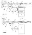
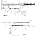
- FIG. 1 On the diagram of the figure 1 can be seen an agricultural machine (3), combine harvester or forage harvester, equipped with wheels and having on its front portion a drive housing (19) mounted on the left side of the power supply that can transmit a rotational movement of the motor to front external tools.
- This training box (19) generally having a splined shaft and allowing the nesting of a splined sleeve, carried by the end of the transmission (20) intended to fit inside the tube to transmit the movement.
- a supply is mounted as well as fixing points (131, 151) which can be lifting arms (13, 15) and / or a feed box on which is positioned a frame (5) solidarisable.
- the mounting of the frame (5) solidarisable is achieved by a monobloc recessed box and associated with locking means.
- An intermediate frame (7) allowing angular deflections along an axis of longitudinal rotation and parallel to the axis of symmetry of the machine, relative to the frame (5) integral with the machine.
- the purpose of these two frames (5, 7) is to allow independent movement of the tools mounted at the front of the agricultural machine relative to the movements of the machine (3), the tools mounted at the front of the machine being in contact with the ground at wheels (37, 43) specific to the agricultural machine.
- the contact of the machine with the ground can also be achieved by means of bogie wheels and / or steel wheels, and / or pads that allow the machine to slide on the ground.
- These means, which ensure the contact of the machine with the ground are for example mounted in pairs on the machine, a means on each of the half-frames (1a, 1b).
- the embodiment of the oscillating frame structure is given for illustrative purposes and any equivalent embodiment can be substituted for it.
- the oscillating frame is formed of a frame, mounted by coupling means on the agricultural machine and an intermediate frame (7) movably carrying the collector, the fixed frame (5) and the intermediate frame (7) movable are connected by a connecting means (8, 10) allowing a relative oscillation of the frames biased by elastic return means to a position of equilibrium and constituting the connecting means (8, 10) oscillating from the collector on the agricultural machine.
- the oscillating frame may have a number of variable link points that surround a space (46) for feeding windrows harvested to the rear of the system.
- the intermediate frame (7) carries directly or indirectly two half-frames (1 a, 1 b).
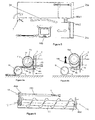
- Each half-frame comprises, as shown on the Figures 8a and 8b , a trough bottom plate (6a, 6b) located near the outermost surface of one of the two inverted mesh Archimedes screws (11a, 11b).
- Each screw is rotatably mounted on an external flank (4aa, respectively 4bb) of the frame and on an inner flank (4ab, 4ba) adjacent to the working position of the inner blank of another half-frame.
- the external flank (4aa, respectively 4bb) of each frame comprises in its housing a mechanism (25a, 25b) for transmitting the movement to the axes of rotation (11c) of each Archimedean screw (11a, 11b) with steps inverted and the two lower tools (9) mounted in the flanks of the half-frame.
- the lower tool (9) in the case of a pick-up will be a rotor with teeth and / or cutting blades, possibly mounted on at least one turntable, but in the case of a cutting-harvester, the lower tool will be a set of teeth actuated by a shearing motion.
- This shearing movement is provided by a drive mechanism (25a, 25b), enclosed in each casing (4aa, 4bb) constituting respectively the left flank of the left half-frame (1a) and the right half-frame (1 b). and such as that shown in Figure 2a .
- Actuation of the two drive mechanisms (25a, 25b) is effected via a transmission axis (250) disposed in the width of the system, parallel to the axis of the tools (9, 11).
- This transmission axis connects at least one gear of the mechanism of the half-frame (1a) which pivots to at least one pinion of the mechanism of the half-frame (1b) which translate.
- This axis can be mounted in the upper or lower half-frames (1a, 1b) by integrating a clutch (251) disposed at the junction between the two half-frames (1a, 1b).
- the transmission shaft (250) is mounted in the upper or lower part of the intermediate frame (7).
- the collector also comprises a comb (17), that is to say a transverse bar provided with teeth, on the top of the collector housing at the level of the toothed rotor (9), for slightly compressing the collected products and the guide towards the entrance of the screw (11).
- the screw (11) brings the gathered windrows towards the inner end of the half-frame, these windrows are then concentrated in the central part of the system to pass towards the rear of the system in the central section (46) of the oscillating frame, at the center of the intermediate frame (7) and the fixed frame (5).
- the half-frames (1a, 1b) have a U-shaped section that support, between each leg of the U, two tools mounted pivoting in the legs of the U.
- the mounted tool upper is formed by a helical screw (11), also called Archimedean screw, while the lower tool (9) is a pickup means formed by a rotor.
- the direction of rotation of the lower rotor (9) is reversed relative to the direction of rotation of the screw of one of the half-frames (1 a, 1 b).
- the helical screw of one of the half-frames has an inverted direction of rotation or an inverted screw pitch relative to the screw of the adjacent half-frame.
- the drive mechanism (25a, 25b) integrated in each of the housings (4aa, 4bb) involves at least one element for varying the speeds of the rotors for driving each of the tools (9, 11), these speeds rotation can vary independently for each of the tools (9, 11).
- the speed of rotation of the lower tool (9) is of the order of 70 to 130 revolutions / minute, lower than that of the Archimedean screw (11), which is of the 150 to 300 revolutions / minute, so that during its operation, the risk of jamming the Archimedean screw is reduced and forage feed is improved.
- a second gear (12) mounted to rotate with the axis (11c) of each helical screw, is also driven by a second chain (16) mounted on the pinion (14a) to give the rotational movement to the helical screw .
- the lower tool (9) is driven at its pinion (18) by a chain, itself driven by a rotor (14b) actuated by the drive unit of the agricultural machine (30).
- the Archimedes screw or helical screw (11) is itself driven by a first chain, rotated by a double gear (14c) of return, actuated by a second chain set in motion by a rotor (14a) controlled by the drive box of the agricultural machine (30).
- rotors rotation transmission mechanisms are adapted to allow the tools to operate with optimal rotational speeds.
- the transmissions are adapted to operate with rotor rotation speeds of 350 to 400 or even 450 or 530 revolutions / minute.
- the rotational transmissions are adapted to allow operation with rotor speeds in the range of 300 to 700 rpm.
- the transmission mechanisms allow adaptation to rotational speeds in the range of 320 to 500 rpm .
- a particular embodiment of the drive of the lower tool is achieved by the action of a rotor that only one side of the device, that is to say at level of only one of the half-frames, for example at the half-frame (1 a) which pivots.
- the transmission of the rotation from one half-frame to another takes place at a junction of rotational drive by clutch at the inner portion where the ends of the two half-frames (1a, 1b) are in contact.
- a flange is disposed vertically and on which the end of the axis of a screw d Archimedes is mounted in rotation.
- This flange is mounted movable relative to the half-frame (1) in a plane substantially perpendicular to the axis of the Archimedean screw to allow movement of at least a portion of the Archimedean screw relative to the bottom of the frame.
- trough disposed on the periphery of at least a portion of the Archimedean screw. The movement of the screw (11) relative to the trough (6) allows a user to have access to the areas likely to be stuffed.
- these mobile flanges are preferably located at the outer ends of the half-frames, they can also be positioned on the inner ends.
- the integration of a speed reduction mechanism or a reverser of direction of rotation to the drive is also part of the invention.
- the pinions (14a, 14b) are respectively mounted on a splined shaft of the drive housing at the input of which is mounted, sliding, a splined shaft (236) which has at its end a dog clutch (23).
- the corrugated tube forms with the shaft (236) a telescopic link in translation which transmits its rotational movement to a clutch (23) displaceable in translation and provided with a ring gear (230) mounted, for example, with two or three teeth (232) intended to fit with the teeth (233, 234) of the ring (235) mounted integral with a transmission shaft (22).
- This transmission shaft (22) is mounted in the upper or lower part of the intermediate frame (7).
- the crowns (230, 235) constitute a so-called clutch system (23), in which the complementary teeth, after a maximum of one-half turn rotation, come mesh when the movable ring (230) biased by the spring (R) towards the fixed portion (235) is engages in the space left free by the teeth (233, 234).
- the complementarity between the two rings (230, 233) is preferably made in such a way that the spaces between the respective teeth (231, 232, 234, 235) of the rings (230, 233) are wider than the teeth (231, 232 , 234, 235) which must be inserted.
- This difference in width allows the crowns (230, 233) to nest more easily with easier insertion of the teeth together during the deployment of the device.
- the greater width of the space between the teeth of a first of the crowns (230, 233) to facilitate the insertion of the teeth of the second crown does not interfere with the quality of the transmission of rotation between the shafts.
- one of the half-jaw is set in translation along the axis of the drive shaft (236) by means of a mechanical and / or hydraulic device, for example jack, which thus allows the disengagement of the half-jaw by exerting a translation that opposes the spring (R) to facilitate the folding of the tool drive system and meshing of the half-jaw by exerting a translation in the direction of the spring when the system is deployed.
- the translation of the half-clutch on the drive shaft takes place at the hub at which the half-clutch interacts with the end of the drive shaft (236), the interaction of the half-clutch on the drive shaft and its hub being achieved by a male / female type engagement.
- the transmission shaft (22) is also integral with a pinion (210, figure 2a3 ), which pinion is intended to receive a double chain to ensure the connection with a second pinion (211) mounted in a housing (21), in a position allowing the transmitting the drive provided by the drive unit of the forage harvester (30) through a gimbal type transmission (20).
- the driving energy supplied by the feed of the agricultural machine (30), via the gearbox (19), to the mechanisms (25) for moving the tools (9, 11) of the machine into operation involves a angle deflection device (19a).
- a first cardan-type transmission shaft (20) facing the front of the vehicle, and / or toward the side of the vehicle that supports the tools
- the angle deflector (19a) transmits the rotational energy to a second transmission shaft (20a) of cardan type which allows a slight oscillation with a pinion (210) connected by a chain to the transmission shaft (22), mounted on the intermediate frame (7), which actuates the axis splined training (236).
- the transmission of the drive energy from the feed (19) of the agricultural machine (30) to the transmission casings (4) of the tools (9, 11) takes place at an axis that passes by the power supply box (19) of the system.
- the intermediate frame (7) positions on its structure a transmission shaft (22) whose axis is aligned with the axis of the transmission shaft (20) which is actuated by the drive housing (19) of the feeding of the agricultural machine (30).
- This transmission shaft (22), rotated at one of its ends by the transmission shaft (20) actuated by the agricultural machine (30), has at its second end a crown intended to allow transmission by clutch (23).
- the transmission involves an angular gearbox (19a) which transmits the rotational energy between a first transmission shaft (20) facing the front face of the vehicle, and / or to the side the vehicle that supports the tools and a second transmission shaft (20bis).
- the second transmission shaft (20a) has an axis which is aligned with that of the transmission shaft (22) supported by the intermediate frame (7) with which it interacts and / or with that of the splined drive shaft (236).
- the two transmission shafts (20, 20a) which intervene with the angular gearbox (19a) are formed by gimbals which allow a slight oscillation during the transmission of the rotational energy or any other type of drive. or transmission, for example clutch or double chain link, allowing or not a slight oscillation in the transmission of the rotation.
- the articulation by clutch (23) also involves a spring (R) so that, once the half-frames (1a, 1b) deployed, the transmission shaft (22) and the drive shaft (236) align and engage the dog clutch (23).
- the Figure 2c shows a peculiarity of the transmission axis (250) which connects the two mechanisms (25) located at the outer ends of the tools (9, 11), the transmission shaft (250) is mounted on the intermediate frame (7) in parallel tools (9, 11). Positioned in this way in the system, the transmission shaft (250) coincides with the splined drive shaft (236) and the drive shaft (22). The end of the transmission shaft extends at its end towards the right part of the intermediate frame by a tube (22b) provided with external splines, which meshes with a female part (22a) of the shaft. transmission (22).
- the grooved tube (22) constitutes with the shaft (22a) a telescopic link in translation and which transmits its rotational movement to a kinematic chain consisting of drive gears (14a, 14b, 12 and 18), identical to that described in connection with the figure 2b for the left part, but located in the casing (4bb) of the right part.
- the left half-frame (1a) and the right half-frame (1b) are hinged to one another by an axis of rotation (2) and the right half-frame (1b) is slidably mounted in parallel translation on the ground with respect to the intermediate frame (7).
- the half-frame (1a) which pivots is pivotally mounted relative to the intermediate frame (7) while the two half-frames (1a, 1b) articulate with each other via a rod (24), for example mounted on the same face of each of the half-frames (1a, 1b) located on the side of the pivot point of the half-frame (1a) which pivots on the intermediate frame (7), so that the translation of the half-frame (1 b) which translate simultaneously causes, by means of the link (24), the rocker half-frame (1a) which pivots.
- a rod (24) for example mounted on the same face of each of the half-frames (1a, 1b) located on the side of the pivot point of the half-frame (1a) which pivots on the intermediate frame (7), so that the translation of the half-frame (1 b) which translate simultaneously causes, by means of the link (24), the rocker half-frame (1a) which pivots.
- the two half-frames (1a, 1b) can articulate independently, being mounted independently on the intermediate frame (7).
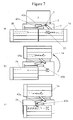
- the road preparation of the device is carried out, as shown in FIG. figure 6 , starting from the working position in which the axis (2) of articulation is arranged so that the two half-frames are placed symmetrically with respect to the machine (3).
- the driver after disengaging the housing (19) for driving actuates one of the control means, for example hydraulic, ensuring the translation of the right half frame (1b) to make a translation shown on the figure 6 to the right, that is to say in the direction of the outer end of the pivoting half-frame 1 a.
- This translation is of sufficient length to allow uncoupling of the dog (23) by releasing the teeth (231, 232) of the teeth (233, 234).
- this translation to uncouple the teeth of the dog (23) can be performed only at the dog and the splined drive shaft (236) with a jack particular and not at the level of the entire right half-frame (1 b) which translate.
- the following step is the control of a jack rotating the left half-frame (1a) to rotate it and bring it above the right half-frame (1b), as shown in part (c) of the figure 6 .
- the users simultaneously or as a result of this rotation in the counterclockwise direction, control the translation of the two superimposed frames to bring them in a symmetrical position relative to the cabin (3) of the machine thanks to a single control element for the two movements of the half-buildings.
- the representation of the figure 6 is a schematic representation of the half-frames seen from the outside by placing itself in front of the machine. All these displacement commands are made by devices for example cylinder, conventional for the skilled person.
- the operations of passage from the road position to the working position will be carried out in the opposite direction by a step of translation of the right half-frame followed by a step of rotation in the clockwise direction of the left half-frame, followed by a step translation of at least one of the half-frames relative to the intermediate frame until engagement of the jaw or compression of the spring (R) and a clutch step of the housing (30) transmission.
- the translation means is constituted by a slide and one or more rollers carried by the frame and the half-frame (1b) which is displaced in translation; the control of the translation, like that of tilting of the half-frame (1a) pivoting, is provided by hydraulic cylinder fed from the hydraulic fluid source of the agricultural machine, or these hydraulic cylinders being controlled by the driver.
- a single cylinder controls both translation and rotation.
- This embodiment may, in the context of a particular embodiment, be carried out so that the half-frame (1a) which pivots is pivotally mounted with respect to the intermediate frame (7) while the two half-frames (1a, 1b) articulate with each other via a connecting rod or an axis (24) or any other type of connection between the two half-frames allowing a concomitant movement between the two half-frames.
- This link or this axis (24) is for example mounted on the same face of each of the half-frames (1a, 1b) located on the side of the articulation point of the half-frame (1a) which pivots on the intermediate frame (7). ).
- the translation of the half-frame (1b) which translates simultaneously causes, by means of the link (24), the rocker half-frame (1a) which pivots, and inversely the rocker half frame (1a) which pivots simultaneously drives the translation of the half-frame (1b) which translates.
- the two half-frames are articulated between them at a level of pivot axis positioned at a contact point located on the inner face of the half-frames, this contact point forming a pivot axis of the half-frames between them.
- the half-frame (1b) which translate is mounted in translation on the intermediate frame (7) while the half-frame (1a) which pivots articulates with the intermediate frame (7) via a rod (24).
- the two half-frames (1a, 1b) can articulate independently, being mounted independently on the intermediate frame (7).
- the translating half-frame (1b) and the mainly pivoting half-frame (1a) each have a thread transfer screw of opposite direction.
- the figure 7 represents another mode of use of the invention in which one has to deal with an agricultural machine equipped with half-frames, one of which, the left half-frame (1a) is pivotally mounted on the intermediate frame (7), and the other half-frame (1b), shown on the left seen from the outside, but located on the right when one is in the cabin, is mounted in translation relative to the intermediate frame (7).
- the clutch system (23) must have teeth allowing disengagement of the teeth during the relative rotation of the half-frames. These teeth will have trapezoidal shapes to allow just the rotation and disengagement of the clutch.
- the spring (R) must be reinforced so that in the working position the dog will not be moved to the position shown in the figure 7 in which the teeth have disengaged.
- the driver simply controls the translation of the right half-frame, to bring it below the left half-frame in a symmetrical position relative to the axis of symmetry of the machine.
- the deployment of the half-frames (1a, 1b) and vice versa, the folding of these half-frames for their transport on the road can be achieved by a successive actuation of cylinders (45a, 45b), pneumatic or hydraulic, by a user of system of the invention, a cylinder that can be used for the displacement, pivoting (45a) or translation (45b), specific to each of the half-frames (1a, 1b) or common to both half-frames (1a, 1b).
- the system integrates one or more end-of-travel devices mounted on the half-frames (1).
- end-of-stroke devices are formed by detectors and / or contactors positioned at strategic points of the half-frames (1) and / or the intermediate frame (7) and associated with switches that stop and / or trigger the operation. defined cylinders. So when the positioning a half-frame by a first cylinder reaches the end of travel and / or when a connector mounted strategically on the half-frame comes into contact with a contactor mounted on the structure of the other half-frame or frame intermediate (7), this contact or this positioning triggers a hydraulic or electrical mechanism that stops the operation of the first cylinder. In addition, according to the movements intended to position the half-frames, the contact or the positioning of the half-frame triggers the operation of at least one second cylinder which controls another displacement for another half-frame.
- limit devices can also be mounted on locking devices (44) of the half-frames (1a, 1b) on the oscillating frame (5, 7) to prevent slackening of the half-frames or on blocking devices the flip-flop of the elements (5, 7) of the oscillating frame to avoid a rocking of the system during the displacement of the half-frames.
- the system of the invention comprises at least one end-of-travel device associated with rotations of the half-frame (1a) which pivots and / or at least one end-of-stroke device. associated with translations of the half-frame (1b) which translates, inwardly and outwardly of the system, relative to the intermediate frame (7).
- a pivoting of the half-frame (1a) concomitant with the translation of the half-frame (1 b) by means of a rod (24) it can be used only one end-of-stroke device for deployment of the system and only one end-of-stroke device for system folding.
- the succession of trips triggered successively by the end-of-travel devices is preprogrammed.
- the engagement of the first movement is performed by the user of the system from a control interface which comprises at least one means for engaging the unfolding of the system in the working position, a means for engaging the folding the system in road position and, optionally, an emergency stop means of travel.
- the intermediate frame must have the widest possible structure but of which the ends, on either side of the system, must not be positioned beyond the points of support of the agricultural machine (30) on the ground. These limits ensure the maintenance of the two half-frames in a volume where they are not likely to move the center of gravity of the system beyond the lift surface of the system mounted on the agricultural machine (30), forage harvester or harvester- harvester.
- the oscillating frame comprises locking means which prevents movement of the intermediate frame (7) relative to the frame (5) solidarisable.
- locking means (44a1, 44a2, 44b) provide a maintenance of half-frames fixed between them.
- Other locking means allow to maintain the two half-frames fixed to a portion of the intermediate frame (44c), for example, in the lower part of the frame.
- These locking means mounted on the half-frames and / or on the oscillating frame can take the form of locking elements paired pair of male / female type.
- the methods comprise a blocking step, respectively unblocking, of the rocking elements of the oscillating frame between them and / or an unlocking step, respectively locking , half-frames (1a, 1b) between them or on the intermediate frame (7).
- the succession of these blocking operations, unlocking and locking, unlocking can be controlled and / or managed by end-of-stroke devices associated or combined with the mechanisms of movement of the half-frames (1 a, 1 b).
Landscapes
- Life Sciences & Earth Sciences (AREA)
- Environmental Sciences (AREA)
- Engineering & Computer Science (AREA)
- Mechanical Engineering (AREA)
- Soil Sciences (AREA)
- Agricultural Machines (AREA)
Applications Claiming Priority (1)
| Application Number | Priority Date | Filing Date | Title |
|---|---|---|---|
| FR0801131A FR2928067B1 (fr) | 2008-02-29 | 2008-02-29 | Systeme d'entrainement mecanique d'au moins un outil d'un engin agricole comportant deux troncons superposables et le procede de preparation au travail ou a la route d'un tel engin. |
Publications (2)
| Publication Number | Publication Date |
|---|---|
| EP2095703A1 true EP2095703A1 (de) | 2009-09-02 |
| EP2095703B1 EP2095703B1 (de) | 2015-04-08 |
Family
ID=39828968
Family Applications (1)
| Application Number | Title | Priority Date | Filing Date |
|---|---|---|---|
| EP20090290145 Not-in-force EP2095703B1 (de) | 2008-02-29 | 2009-02-27 | Mechanisches Antriebssystem mindestens eines Werkzeugs einer landwirtschaftlichen Maschine, das über zwei übereinander positionierbare Spurstangen verfügt, und Verfahren zur Arbeits- oder Fahrvorbereitung einer solchen Maschine |
Country Status (2)
| Country | Link |
|---|---|
| EP (1) | EP2095703B1 (de) |
| FR (1) | FR2928067B1 (de) |
Cited By (4)
| Publication number | Priority date | Publication date | Assignee | Title |
|---|---|---|---|---|
| ITPD20120346A1 (it) * | 2012-11-13 | 2014-05-14 | Marangon Srl | Macchina trinciatrice/falciatrice, condizionatrice, andanatrice |
| FR3031648A1 (fr) * | 2015-01-16 | 2016-07-22 | Desvoys Et Fils | Dispositif agricole destine a etre attele a un vehicule tracteur, comprenant au moins un chassis repliable comportant un outil rotatif |
| WO2016147059A1 (en) * | 2015-03-17 | 2016-09-22 | Marangon Srl | Cutter head of shredder/mower, conditioner, windrower, with oscillating auger in three or more portions |
| EP4169370A1 (de) * | 2021-10-22 | 2023-04-26 | Maschinenfabrik Bernard Krone GmbH & Co. KG | Vorsatzgerät für eine landmaschine |
Citations (8)
| Publication number | Priority date | Publication date | Assignee | Title |
|---|---|---|---|---|
| GB1275492A (en) * | 1969-06-02 | 1972-05-24 | Clayson Nv | Improvements in or relating to harvesting machines |
| EP0373406A1 (de) | 1988-12-16 | 1990-06-20 | Claas Ohg | Selbstfahrender Mähdrescher mit geteiltem Schneidwerk |
| EP0442067A1 (de) | 1990-02-16 | 1991-08-21 | Claas Ohg | Landwirtschafliche Maschine mit einer front- oder heckseitigen Arbeitsvorrichtung |
| FR2776467A1 (fr) | 1998-03-27 | 1999-10-01 | Idass Sa | Dispositif de fixation oscillant pour engin agricole |
| FR2781118A1 (fr) | 1998-07-16 | 2000-01-21 | Bmv | Equipement d'ensileuse |
| EP1378158A1 (de) * | 2002-05-31 | 2004-01-07 | F.LLI CRESSONI SpA | Viehfuttersammelvorrichtung |
| FR2868905A1 (fr) * | 2004-04-19 | 2005-10-21 | Idass Sarl | Pick up repliable a entrainement independant des deux elements de vis sans fin |
| CA2530169A1 (en) * | 2005-12-15 | 2007-06-15 | Deere & Company | Drive for a crop picking head |
-
2008
- 2008-02-29 FR FR0801131A patent/FR2928067B1/fr not_active Expired - Fee Related
-
2009
- 2009-02-27 EP EP20090290145 patent/EP2095703B1/de not_active Not-in-force
Patent Citations (8)
| Publication number | Priority date | Publication date | Assignee | Title |
|---|---|---|---|---|
| GB1275492A (en) * | 1969-06-02 | 1972-05-24 | Clayson Nv | Improvements in or relating to harvesting machines |
| EP0373406A1 (de) | 1988-12-16 | 1990-06-20 | Claas Ohg | Selbstfahrender Mähdrescher mit geteiltem Schneidwerk |
| EP0442067A1 (de) | 1990-02-16 | 1991-08-21 | Claas Ohg | Landwirtschafliche Maschine mit einer front- oder heckseitigen Arbeitsvorrichtung |
| FR2776467A1 (fr) | 1998-03-27 | 1999-10-01 | Idass Sa | Dispositif de fixation oscillant pour engin agricole |
| FR2781118A1 (fr) | 1998-07-16 | 2000-01-21 | Bmv | Equipement d'ensileuse |
| EP1378158A1 (de) * | 2002-05-31 | 2004-01-07 | F.LLI CRESSONI SpA | Viehfuttersammelvorrichtung |
| FR2868905A1 (fr) * | 2004-04-19 | 2005-10-21 | Idass Sarl | Pick up repliable a entrainement independant des deux elements de vis sans fin |
| CA2530169A1 (en) * | 2005-12-15 | 2007-06-15 | Deere & Company | Drive for a crop picking head |
Cited By (5)
| Publication number | Priority date | Publication date | Assignee | Title |
|---|---|---|---|---|
| ITPD20120346A1 (it) * | 2012-11-13 | 2014-05-14 | Marangon Srl | Macchina trinciatrice/falciatrice, condizionatrice, andanatrice |
| WO2014076600A1 (en) * | 2012-11-13 | 2014-05-22 | Marangon Srl | Cutting/mowing, conditioning, windrowing machine |
| FR3031648A1 (fr) * | 2015-01-16 | 2016-07-22 | Desvoys Et Fils | Dispositif agricole destine a etre attele a un vehicule tracteur, comprenant au moins un chassis repliable comportant un outil rotatif |
| WO2016147059A1 (en) * | 2015-03-17 | 2016-09-22 | Marangon Srl | Cutter head of shredder/mower, conditioner, windrower, with oscillating auger in three or more portions |
| EP4169370A1 (de) * | 2021-10-22 | 2023-04-26 | Maschinenfabrik Bernard Krone GmbH & Co. KG | Vorsatzgerät für eine landmaschine |
Also Published As
| Publication number | Publication date |
|---|---|
| FR2928067B1 (fr) | 2012-05-18 |
| EP2095703B1 (de) | 2015-04-08 |
| FR2928067A1 (fr) | 2009-09-04 |
Similar Documents
| Publication | Publication Date | Title |
|---|---|---|
| EP0556143B1 (de) | Mähmaschine mit einer verbesserten Verriegelungsvorrichtung | |
| EP1349998B1 (de) | Rollvorrichtung mit selbstantrieb zur reinigung einer eingetauchten fläche mit einem oder mehreren lösbaren rollgliedern | |
| EP0163587B1 (de) | Mähmaschine | |
| EP0800757B1 (de) | Landmaschine mit einem drehbaren Verbindungsmittel an einen Traktor und mit einem drehbaren Getriebegehäuse | |
| EP2731414B1 (de) | Gelenkige Aufnehmervorrichtung und landwirtschaftliche Maschine mit einer solchen Vorrichtung | |
| EP0385899B1 (de) | Heuwerbungsmaschine mit mehreren Kreiseln | |
| EP2095703B1 (de) | Mechanisches Antriebssystem mindestens eines Werkzeugs einer landwirtschaftlichen Maschine, das über zwei übereinander positionierbare Spurstangen verfügt, und Verfahren zur Arbeits- oder Fahrvorbereitung einer solchen Maschine | |
| EP1496734B1 (de) | Heuwerbungsmaschine | |
| EP0242311B1 (de) | Rotations-Mähwerk mit Mähbalken und Trägerstruktur | |
| EP3113597B1 (de) | Vorrichtung zum anhängen eines werkzeugs, wie etwa ein landwirtschaftliches werkzeug, an ein zugsystem eines fahrzeugs, wie etwa ein landwirtschaftlicher traktor | |
| FR2619986A1 (fr) | Mecanisme de raccordement d'un outil de travail a un tracteur | |
| EP0552120B1 (de) | Heumaschine mit dynamischer Entlastungsvorrichtung | |
| EP0300937B1 (de) | Heuwerbungsmaschine mit mehreren einschwenkbaren Rechrädern zum Zusammenlegen für den Transport oder die Unterbringung | |
| EP0755621B1 (de) | Klappbare Erntegutaufnahmevorrichtung | |
| EP0981944A1 (de) | Selbsttragender Rasenmäher, Verfahren zur Herstellung und Kitt zu seiner Durchführung | |
| FR2685162A1 (fr) | Dispositif cueilleur repliable pour la recolte du mauis ou plantes similaires. | |
| EP0558430B1 (de) | Heuschwader mit einem Mechanismus zur Unterbrechung des Rotorantriebes | |
| FR2781118A1 (fr) | Equipement d'ensileuse | |
| EP3235364A1 (de) | Erntevorrichtung mit einer perfektionierten wellenanordnung, und landwirtschaftliche maschine, die mit einer solchen erntevorrichtung ausgestattet ist | |
| FR2868905A1 (fr) | Pick up repliable a entrainement independant des deux elements de vis sans fin | |
| EP0071555A1 (de) | Maschine zur Entnahme von Futterballen aus einem Silo | |
| EP0655188B1 (de) | Heuwerbungsmaschine | |
| FR2749128A1 (fr) | Machine de recolte, en particulier moissonneuse-batteuse, comprenant un outil frontal compose d'au moins deux parties repliables | |
| EP1523232B1 (de) | Heumaschine | |
| FR3145078A1 (fr) | Machine de fenaison améliorée |
Legal Events
| Date | Code | Title | Description |
|---|---|---|---|
| PUAI | Public reference made under article 153(3) epc to a published international application that has entered the european phase |
Free format text: ORIGINAL CODE: 0009012 |
|
| AK | Designated contracting states |
Kind code of ref document: A1 Designated state(s): AT BE BG CH CY CZ DE DK EE ES FI FR GB GR HR HU IE IS IT LI LT LU LV MC MK MT NL NO PL PT RO SE SI SK TR |
|
| AX | Request for extension of the european patent |
Extension state: AL BA RS |
|
| 17P | Request for examination filed |
Effective date: 20100224 |
|
| AKX | Designation fees paid |
Designated state(s): AT BE BG CH CY CZ DE DK EE ES FI FR GB GR HR HU IE IS IT LI LT LU LV MC MK MT NL NO PL PT RO SE SI SK TR |
|
| REG | Reference to a national code |
Ref country code: DE Ref legal event code: R079 Ref document number: 602009030456 Country of ref document: DE Free format text: PREVIOUS MAIN CLASS: A01D0089000000 Ipc: A01B0073040000 |
|
| GRAP | Despatch of communication of intention to grant a patent |
Free format text: ORIGINAL CODE: EPIDOSNIGR1 |
|
| RIC1 | Information provided on ipc code assigned before grant |
Ipc: A01D 41/14 20060101ALI20141014BHEP Ipc: A01D 89/00 20060101ALI20141014BHEP Ipc: A01B 73/04 20060101AFI20141014BHEP |
|
| INTG | Intention to grant announced |
Effective date: 20141029 |
|
| GRAS | Grant fee paid |
Free format text: ORIGINAL CODE: EPIDOSNIGR3 |
|
| RIN1 | Information on inventor provided before grant (corrected) |
Inventor name: BIZEUL, JEAN-MARC |
|
| GRAA | (expected) grant |
Free format text: ORIGINAL CODE: 0009210 |
|
| AK | Designated contracting states |
Kind code of ref document: B1 Designated state(s): AT BE BG CH CY CZ DE DK EE ES FI FR GB GR HR HU IE IS IT LI LT LU LV MC MK MT NL NO PL PT RO SE SI SK TR |
|
| REG | Reference to a national code |
Ref country code: GB Ref legal event code: FG4D Free format text: NOT ENGLISH |
|
| REG | Reference to a national code |
Ref country code: CH Ref legal event code: EP |
|
| REG | Reference to a national code |
Ref country code: IE Ref legal event code: FG4D Free format text: LANGUAGE OF EP DOCUMENT: FRENCH |
|
| REG | Reference to a national code |
Ref country code: AT Ref legal event code: REF Ref document number: 719764 Country of ref document: AT Kind code of ref document: T Effective date: 20150515 |
|
| REG | Reference to a national code |
Ref country code: DE Ref legal event code: R096 Ref document number: 602009030456 Country of ref document: DE Effective date: 20150521 |
|
| REG | Reference to a national code |
Ref country code: AT Ref legal event code: MK05 Ref document number: 719764 Country of ref document: AT Kind code of ref document: T Effective date: 20150408 |
|
| REG | Reference to a national code |
Ref country code: NL Ref legal event code: VDEP Effective date: 20150408 |
|
| REG | Reference to a national code |
Ref country code: LT Ref legal event code: MG4D |
|
| PG25 | Lapsed in a contracting state [announced via postgrant information from national office to epo] |
Ref country code: NL Free format text: LAPSE BECAUSE OF FAILURE TO SUBMIT A TRANSLATION OF THE DESCRIPTION OR TO PAY THE FEE WITHIN THE PRESCRIBED TIME-LIMIT Effective date: 20150408 |
|
| PG25 | Lapsed in a contracting state [announced via postgrant information from national office to epo] |
Ref country code: ES Free format text: LAPSE BECAUSE OF FAILURE TO SUBMIT A TRANSLATION OF THE DESCRIPTION OR TO PAY THE FEE WITHIN THE PRESCRIBED TIME-LIMIT Effective date: 20150408 Ref country code: HR Free format text: LAPSE BECAUSE OF FAILURE TO SUBMIT A TRANSLATION OF THE DESCRIPTION OR TO PAY THE FEE WITHIN THE PRESCRIBED TIME-LIMIT Effective date: 20150408 Ref country code: NO Free format text: LAPSE BECAUSE OF FAILURE TO SUBMIT A TRANSLATION OF THE DESCRIPTION OR TO PAY THE FEE WITHIN THE PRESCRIBED TIME-LIMIT Effective date: 20150708 Ref country code: PT Free format text: LAPSE BECAUSE OF FAILURE TO SUBMIT A TRANSLATION OF THE DESCRIPTION OR TO PAY THE FEE WITHIN THE PRESCRIBED TIME-LIMIT Effective date: 20150810 Ref country code: FI Free format text: LAPSE BECAUSE OF FAILURE TO SUBMIT A TRANSLATION OF THE DESCRIPTION OR TO PAY THE FEE WITHIN THE PRESCRIBED TIME-LIMIT Effective date: 20150408 Ref country code: LT Free format text: LAPSE BECAUSE OF FAILURE TO SUBMIT A TRANSLATION OF THE DESCRIPTION OR TO PAY THE FEE WITHIN THE PRESCRIBED TIME-LIMIT Effective date: 20150408 |
|
| PG25 | Lapsed in a contracting state [announced via postgrant information from national office to epo] |
Ref country code: AT Free format text: LAPSE BECAUSE OF FAILURE TO SUBMIT A TRANSLATION OF THE DESCRIPTION OR TO PAY THE FEE WITHIN THE PRESCRIBED TIME-LIMIT Effective date: 20150408 Ref country code: IS Free format text: LAPSE BECAUSE OF FAILURE TO SUBMIT A TRANSLATION OF THE DESCRIPTION OR TO PAY THE FEE WITHIN THE PRESCRIBED TIME-LIMIT Effective date: 20150808 Ref country code: GR Free format text: LAPSE BECAUSE OF FAILURE TO SUBMIT A TRANSLATION OF THE DESCRIPTION OR TO PAY THE FEE WITHIN THE PRESCRIBED TIME-LIMIT Effective date: 20150709 Ref country code: LV Free format text: LAPSE BECAUSE OF FAILURE TO SUBMIT A TRANSLATION OF THE DESCRIPTION OR TO PAY THE FEE WITHIN THE PRESCRIBED TIME-LIMIT Effective date: 20150408 |
|
| REG | Reference to a national code |
Ref country code: DE Ref legal event code: R097 Ref document number: 602009030456 Country of ref document: DE |
|
| PG25 | Lapsed in a contracting state [announced via postgrant information from national office to epo] |
Ref country code: EE Free format text: LAPSE BECAUSE OF FAILURE TO SUBMIT A TRANSLATION OF THE DESCRIPTION OR TO PAY THE FEE WITHIN THE PRESCRIBED TIME-LIMIT Effective date: 20150408 Ref country code: DK Free format text: LAPSE BECAUSE OF FAILURE TO SUBMIT A TRANSLATION OF THE DESCRIPTION OR TO PAY THE FEE WITHIN THE PRESCRIBED TIME-LIMIT Effective date: 20150408 |
|
| PLBE | No opposition filed within time limit |
Free format text: ORIGINAL CODE: 0009261 |
|
| STAA | Information on the status of an ep patent application or granted ep patent |
Free format text: STATUS: NO OPPOSITION FILED WITHIN TIME LIMIT |
|
| REG | Reference to a national code |
Ref country code: FR Ref legal event code: PLFP Year of fee payment: 8 |
|
| PG25 | Lapsed in a contracting state [announced via postgrant information from national office to epo] |
Ref country code: PL Free format text: LAPSE BECAUSE OF FAILURE TO SUBMIT A TRANSLATION OF THE DESCRIPTION OR TO PAY THE FEE WITHIN THE PRESCRIBED TIME-LIMIT Effective date: 20150408 Ref country code: SK Free format text: LAPSE BECAUSE OF FAILURE TO SUBMIT A TRANSLATION OF THE DESCRIPTION OR TO PAY THE FEE WITHIN THE PRESCRIBED TIME-LIMIT Effective date: 20150408 Ref country code: RO Free format text: LAPSE BECAUSE OF NON-PAYMENT OF DUE FEES Effective date: 20150408 Ref country code: CZ Free format text: LAPSE BECAUSE OF FAILURE TO SUBMIT A TRANSLATION OF THE DESCRIPTION OR TO PAY THE FEE WITHIN THE PRESCRIBED TIME-LIMIT Effective date: 20150408 |
|
| 26N | No opposition filed |
Effective date: 20160111 |
|
| PG25 | Lapsed in a contracting state [announced via postgrant information from national office to epo] |
Ref country code: IT Free format text: LAPSE BECAUSE OF FAILURE TO SUBMIT A TRANSLATION OF THE DESCRIPTION OR TO PAY THE FEE WITHIN THE PRESCRIBED TIME-LIMIT Effective date: 20150408 |
|
| PG25 | Lapsed in a contracting state [announced via postgrant information from national office to epo] |
Ref country code: SI Free format text: LAPSE BECAUSE OF FAILURE TO SUBMIT A TRANSLATION OF THE DESCRIPTION OR TO PAY THE FEE WITHIN THE PRESCRIBED TIME-LIMIT Effective date: 20150408 Ref country code: BE Free format text: LAPSE BECAUSE OF NON-PAYMENT OF DUE FEES Effective date: 20160229 |
|
| PG25 | Lapsed in a contracting state [announced via postgrant information from national office to epo] |
Ref country code: MC Free format text: LAPSE BECAUSE OF FAILURE TO SUBMIT A TRANSLATION OF THE DESCRIPTION OR TO PAY THE FEE WITHIN THE PRESCRIBED TIME-LIMIT Effective date: 20150408 Ref country code: LU Free format text: LAPSE BECAUSE OF FAILURE TO SUBMIT A TRANSLATION OF THE DESCRIPTION OR TO PAY THE FEE WITHIN THE PRESCRIBED TIME-LIMIT Effective date: 20160227 |
|
| REG | Reference to a national code |
Ref country code: CH Ref legal event code: PL |
|
| PG25 | Lapsed in a contracting state [announced via postgrant information from national office to epo] |
Ref country code: CH Free format text: LAPSE BECAUSE OF NON-PAYMENT OF DUE FEES Effective date: 20160229 Ref country code: LI Free format text: LAPSE BECAUSE OF NON-PAYMENT OF DUE FEES Effective date: 20160229 |
|
| REG | Reference to a national code |
Ref country code: IE Ref legal event code: MM4A |
|
| PG25 | Lapsed in a contracting state [announced via postgrant information from national office to epo] |
Ref country code: IE Free format text: LAPSE BECAUSE OF NON-PAYMENT OF DUE FEES Effective date: 20160227 |
|
| REG | Reference to a national code |
Ref country code: FR Ref legal event code: PLFP Year of fee payment: 9 |
|
| PG25 | Lapsed in a contracting state [announced via postgrant information from national office to epo] |
Ref country code: SE Free format text: LAPSE BECAUSE OF FAILURE TO SUBMIT A TRANSLATION OF THE DESCRIPTION OR TO PAY THE FEE WITHIN THE PRESCRIBED TIME-LIMIT Effective date: 20150408 |
|
| PG25 | Lapsed in a contracting state [announced via postgrant information from national office to epo] |
Ref country code: MT Free format text: LAPSE BECAUSE OF FAILURE TO SUBMIT A TRANSLATION OF THE DESCRIPTION OR TO PAY THE FEE WITHIN THE PRESCRIBED TIME-LIMIT Effective date: 20150408 |
|
| REG | Reference to a national code |
Ref country code: FR Ref legal event code: PLFP Year of fee payment: 10 |
|
| PG25 | Lapsed in a contracting state [announced via postgrant information from national office to epo] |
Ref country code: CY Free format text: LAPSE BECAUSE OF FAILURE TO SUBMIT A TRANSLATION OF THE DESCRIPTION OR TO PAY THE FEE WITHIN THE PRESCRIBED TIME-LIMIT Effective date: 20150408 Ref country code: HU Free format text: LAPSE BECAUSE OF FAILURE TO SUBMIT A TRANSLATION OF THE DESCRIPTION OR TO PAY THE FEE WITHIN THE PRESCRIBED TIME-LIMIT; INVALID AB INITIO Effective date: 20090227 |
|
| PG25 | Lapsed in a contracting state [announced via postgrant information from national office to epo] |
Ref country code: MK Free format text: LAPSE BECAUSE OF FAILURE TO SUBMIT A TRANSLATION OF THE DESCRIPTION OR TO PAY THE FEE WITHIN THE PRESCRIBED TIME-LIMIT Effective date: 20150408 Ref country code: TR Free format text: LAPSE BECAUSE OF FAILURE TO SUBMIT A TRANSLATION OF THE DESCRIPTION OR TO PAY THE FEE WITHIN THE PRESCRIBED TIME-LIMIT Effective date: 20150408 |
|
| PG25 | Lapsed in a contracting state [announced via postgrant information from national office to epo] |
Ref country code: BG Free format text: LAPSE BECAUSE OF FAILURE TO SUBMIT A TRANSLATION OF THE DESCRIPTION OR TO PAY THE FEE WITHIN THE PRESCRIBED TIME-LIMIT Effective date: 20150408 |
|
| PGFP | Annual fee paid to national office [announced via postgrant information from national office to epo] |
Ref country code: DE Payment date: 20190327 Year of fee payment: 11 Ref country code: GB Payment date: 20190328 Year of fee payment: 11 |
|
| PGFP | Annual fee paid to national office [announced via postgrant information from national office to epo] |
Ref country code: FR Payment date: 20190226 Year of fee payment: 11 |
|
| REG | Reference to a national code |
Ref country code: DE Ref legal event code: R119 Ref document number: 602009030456 Country of ref document: DE |
|
| GBPC | Gb: european patent ceased through non-payment of renewal fee |
Effective date: 20200227 |
|
| PG25 | Lapsed in a contracting state [announced via postgrant information from national office to epo] |
Ref country code: GB Free format text: LAPSE BECAUSE OF NON-PAYMENT OF DUE FEES Effective date: 20200227 Ref country code: FR Free format text: LAPSE BECAUSE OF NON-PAYMENT OF DUE FEES Effective date: 20200229 Ref country code: DE Free format text: LAPSE BECAUSE OF NON-PAYMENT OF DUE FEES Effective date: 20200901 |