EP2095704B1 - Schneidemaschine, insbesondere für den Einsatz im Weinbau, die mit einem Werkzeug für Ranken und einer Anschleifvorrichtung ausgestattet ist - Google Patents
Schneidemaschine, insbesondere für den Einsatz im Weinbau, die mit einem Werkzeug für Ranken und einer Anschleifvorrichtung ausgestattet ist Download PDFInfo
- Publication number
- EP2095704B1 EP2095704B1 EP09153233A EP09153233A EP2095704B1 EP 2095704 B1 EP2095704 B1 EP 2095704B1 EP 09153233 A EP09153233 A EP 09153233A EP 09153233 A EP09153233 A EP 09153233A EP 2095704 B1 EP2095704 B1 EP 2095704B1
- Authority
- EP
- European Patent Office
- Prior art keywords
- tool
- cutting
- cutting machine
- machine according
- module
- Prior art date
- Legal status (The legal status is an assumption and is not a legal conclusion. Google has not performed a legal analysis and makes no representation as to the accuracy of the status listed.)
- Active
Links
Images


Classifications
-
- A—HUMAN NECESSITIES
- A01—AGRICULTURE; FORESTRY; ANIMAL HUSBANDRY; HUNTING; TRAPPING; FISHING
- A01G—HORTICULTURE; CULTIVATION OF VEGETABLES, FLOWERS, RICE, FRUIT, VINES, HOPS OR SEAWEED; FORESTRY; WATERING
- A01G17/00—Cultivation of hops, vines, fruit trees, or like trees
- A01G17/02—Cultivation of hops or vines
-
- A—HUMAN NECESSITIES
- A01—AGRICULTURE; FORESTRY; ANIMAL HUSBANDRY; HUNTING; TRAPPING; FISHING
- A01G—HORTICULTURE; CULTIVATION OF VEGETABLES, FLOWERS, RICE, FRUIT, VINES, HOPS OR SEAWEED; FORESTRY; WATERING
- A01G3/00—Cutting implements specially adapted for horticultural purposes; Delimbing standing trees
- A01G3/04—Apparatus for trimming hedges, e.g. hedge shears
- A01G3/0408—Apparatus for trimming hedges, e.g. hedge shears specially adapted for trellis work, e.g. machines for pruning vine or the like
Definitions
- the present invention relates to a cutting machine that can be used in agriculture, arboriculture or viticulture, comprising a cutting head having at least one pair of modules, according to the preamble of independent claim 1.
- this machine can be provided with a device allowing the operator, whenever he deems it necessary, to sharpen this tool on site.
- the invention focuses essentially on the entire lower part of the cutting machines of the aforementioned kind in order to significantly improve their operation and comfort of use.
- EP-A-0 147 344 discloses a cutting machine of which at least one of the two cutting modules may comprise a tool inclined forward and formed of two disks pressed against each other to produce a shear cut.
- One of these disks connected to a vertical upright of a bearing structure of the cutting module, is fixed and has at its periphery, on a defined circular arc, an alternation of teeth and notches.
- the other disc is rotated like the toothed and ribbed disk of the cutting tools of the cutting module and has an alternation of teeth and notches throughout its periphery.
- the spool tool (like all other tools that this machine is equipped with) has a fixed element and a movable element to produce shear sectioning.
- EP-A-0 696 416 discloses a cutting machine having a cutting module and a feeding module.
- the lower cutting tool is similar to that of the tools stacked above it, that is to say essentially consisting of a circular saw rotated at high speed and a cage surrounding it entirely. , also driven in rotation, but at a speed whose tangential component corresponds approximately to the forward speed of the tractor to which the machine is coupled.
- the saw teeth of this lower cutting tool is substantially thinner than that of the upper saws.
- This machine can also be equipped with a specific tool according to EP-A-0 696 417 to spare spurs, but does not have the function of producing a cut.
- the objectives (2) and (3) are achieved, but the user must however accommodate a cutting quality (objective (1)) questionable.
- the objective (4) (comfort of use) is not the object of particular criticism, since the questions of a restoration and even less of a premature replacement of the lower cutting tool practically do not arise.
- EP-A-1,825,744 discloses a cutting machine which may be provided with an optional tool which differs from the cutting tools arranged above it, in that it comprises two elements cooperating with one another and consisting essentially of one a fixed plate, connected to the carrier structure of the module and having on a defined sector oriented towards the front of the fingers and the other, a rotated disc, whose entire periphery is provided with an alternation of sharp knives and indentations.
- the fingers of the fixed plate emerge out of the outer circle determined by the end portions of the knives, so as to channel the branches and ensure the maintenance of the latter just before the cut occurs, which is produced by shearing and without breaking of the courson.
- US-2006/0162309 describes a cutting machine of the commented kind, the result of a juxtaposition of known means, in particular EP-0 147 344 and of EP-0 696 416 .
- Each of the two cutting modules has at its bottom a spur tool essentially comprising two elements.
- a first toothed disk member is rotated.
- a second element also has a general disk shape. Constituted, on a sector of about 180 ° each time, a toothed portion facing the other module and a non-toothed portion serving protection, this second element is fixed.
- the diameter of this tool to courson is "slightly lower" to the diameter of the cutting tools of the module arranged above him, in order to decrease the risk of engagement of objects at this level.
- the two elements cooperate with each other to produce a shear cut.
- the object of the present invention is to propose a cutting machine of the type of those commented, which is, on the one hand, provided with at least one tool with courson to achieve cumulatively the objectives (1) to ( 4) listed above and, on the other hand, optionally equipped with a device for sharpening this tool to achieve the objective (5), this device can be implemented as needed and very good on the parcel or at the very place where the machine is moving momentarily, so that the initial quality of the bobbins is always maintained, over a long period of time and without any other intervention, the machine is immobilized in a workshop. imposing itself more than for the sole purpose of an imperative replacement of a tool with a spur that has reached an irretrievable threshold of wear, which occurs, in viticulture for example, after pruning or pruning on an average surface of the order some 800 hectares.
- the cutting head shown in figure 1 corresponds to that described in EP-A-1,825,744 , to which this example refers: it consists of two cutting modules [A], [B], axes A1, B1, substantially vertical, carried by a frame 8 can be coupled to a tractor (not shown), with pivoting abilities about axes A2, B2, respectively, parallel to the axes A1, B1, and to be rotated under the action of hydraulic motors 9 and 10 (arrows R (A) and R (B)), preferably at speeds in the range of [250 - 300] rpm, the speeds of rotation of the two modules being able, but not necessarily, to be equal to each other.
- Each cutting module rests on a support bearing 5; 6 and is formed of at least one cutting tool, usually a stack of a plurality of tools 3; 4 whose periphery has active elements, that is to say elements directly involved in the cutting operation, in this case teeth (not referenced), the tools of a module can interpenetrate in defined spaces e1 arranged between the tools of the other module, so as to allow said modules to adopt any appropriate positions between maximum positions of opening and closing during the implementation of the machine and more particularly during the operations of chopped off.
- the modules cooperate with each other in that they channel the vegetation in a median space where it will be reduced to a plurality of sections.
- each cutting tool makes its cuts, whether by shearing or sawing, independently of any other cutting tool of the other module, a cutting tool comprising, as a rule, two elements of which at least one is rotated.
- each cut results from mutual actions, and therefore from an interaction, between a cutting tool 3 of the module [A] and an associated cutting tool 4 of the module [B].
- These tools 3, 4, identical, of defined height h advantageously greater than 3 mm and preferably equal to about 15 mm, are each arranged inversely with respect to each other, the quality of the cut being adaptable by adjusting a space e2 between the upper and lower faces (not referenced) of cutting tools 3, 4 associated.
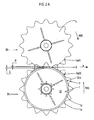
- the lower tools of the modules [A; B], that is to say, according to the arrangement of the figure 1 , the spur tool 1 and the cutting tool 4, and, depending on the arrangement of the figure 3 , the courson tools 1, 2, are mounted under the bearing bearings 5, 6, so as to avoid any damage that may cause the shock, including the courson, a part of the machine.
- the spool tool 1 of the stack of tools of the module [A] differs from the other tools 3 stacked above it, in that it is formed of a circular disk of thickness ⁇ , of which the periphery is bevelled to form a continuous cutting edge 14 (the bevel 13 being oriented downwards, in other words, the apex of the cone whose envelope contains this bevel is located under the stack of the module, by definition on the axis A1 of it).
- the value ⁇ , relatively small in comparison with the height h preferred tools 3, 4 is advantageously in a range of about 3 to 6 mm, and preferably equal to 4.0 mm or 4.5 mm.
- the plane Ps (1) of the upper face 11 of this tool 1 extends under the plane Pi (4) of the lower face of the first cutting tool 4 of the stack of the module [B], these two parallel planes Ps (1), Pi (4) being separated by a distance ⁇ constituting a functional game, easily adjustable through a known adjustment device 7. Numerous tests have shown that the value ⁇ is advantageously in a range of about 1 to 4 mm.
- the outer diameter D (1) of the spur tool 1 is smaller than the base diameter Dp (3) of the cutting tool 3 (hence of the diameter from which the aforementioned active elements emerge, namely the teeth), which, in addition to providing a quality cut, avoids any collision of the peripheral cutting edge 14 of the tool courson 1 against the trestle posts, even strongly inclined, therefore any damage to these and tool 1 itself.
- the difference (Dp (3) - D (1)) is equal to 2 ⁇ , the value ⁇ advantageously being in a range of about 0.1 to 20 mm and preferably equal to about 5 mm.
- the foot circumference of diameter Dp (4) of the cutting tool 4 overflows the outer circumference of diameter D (1) of the tool of courson 1, over a length ⁇ , which ensures a smaller size of the branches well completed and therefore eliminates any risk of chipping of the courson thus formed.
- the value of ⁇ is advantageously in a range of about 15 to 50 mm and preferably equal to about 30 mm.
- the trellising wire is subjected, throughout the course of the cutting operations, to different forces, the resultants act on it so that it can only slide or evolve under the face 12 of the tool 1, or on the upper face (not referenced) of the cutting tool 4 with which said tool to courson interacts to produce the section, or, more sporadically, between the face 11 of the tool 1 and the lower face (plane Pi (4)) of the tool 4, or, finally, to move from one of these states to another, but this, without ever being able to be hung or sheared.
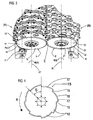
- the figure 3 which is a partial perspective of the front of the cutting machine, shows a mounting variant according to which the lower tool of the module [B], arranged under the bearing 6 ( figure 1 ), is also a tool to courson.
- the latter, reference 2 is identical to the tool to courson 1, except that it is mounted in a position opposite to that of the tool 1, the plane Ps (1) of the face 11 (see also figure 1 ) extending under the plane (not shown) of the face 21 of the tool 2, the bevel 23 being, unlike the bevel 13, facing upwards.
- a clearance ⁇ separates the planes of the faces 11, 21 of the tools 1, 2 respectively.
- the Figure 2B is a view from below of the figure 3 . It is analogous to the Figure 2A , so that the explanations given in support of the latter, in particular those concerning the parameters ⁇ and ⁇ , apply mutatis mutandis. It will be observed only that the size of the spurs results from the interaction of the active parts 13, 14; 23, 24, in particular cutting edges 14, 24 of courson tools 1, 2 producing a shear cut. However, the cut of the courson intervening at the intersection of the cutting edges 14, 24 (the zone Z extending, according to this mounting variant, around this intersection), can be performed on two levels. If it remains in itself of excellent quality, it is likely to be staged, at least on some coursons, the distance between the two cutting planes on the spur corresponding approximately to the value ⁇ .
- the lower tool of one of the modules will be a tool to run 1 or 2 arranged so that it is able to interact with a lower tool of the other module and that all the conditions, in particular geometric, described above, are respected.
- this lower tool of the other module could be of the type of the tool 4 or 3, or a tool with courson 2 or 1. It is understood that the assembly of two tools with courson 1, 2 is not deprived of interest for all these other kinds of cutting machines.
- the figure 4 shows a runner tool as a possible alternative embodiment.
- This tool has a discontinuous cutting edge 18, in that it is distributed over a succession of bevelled sectors 16 of angle ⁇ , each having a bevel 17.
- the cutting edges 17 are slightly curved and are subsequently connected one to the other.
- Another means of a segment 19. In order to avoid any attachment with a surrounding element, during its rotation, it is important for this tool 15 to be mounted so that said segment 19 does not appear against the direction of rotation R. This is on the contrary, each incurvation 17 which follows this direction.
- the tangential component of the rotational speed of the tools of one module is greater than the tangential component of the rotational speed of the other one module, which allows an optimal ejection of the segments of shoots cut out of the trellis son , especially of those who are wrapped around these.
- the highest rotational speed be applied to this module.
- the relative difference between these tangential components is equal to a value ⁇ and is preferably in a range of about 20 to 40%.
- the sharpening device consists of means that can be grouped, functionally, into four subgroups, namely a sharpening block, a set connecting elements connecting this block to the cutting machine and allowing it to be moved from a passive (ie waiting) position to an active (ie working) position and vice versa, a set of adjustment means of said block relative to the lower tool to be sharpened to ensure a correct sharpening and quality of this tool and, finally, means for actuating and guiding the block, necessary to perform sharpening operations.
- the first embodiment 30 is shown in Figures 5 and 6 , with a grinding block 40 in passive and active positions respectively, on a cutting machine corresponding to that shown in FIG. figure 1 whose module [A] is equipped with a tool 1.
- the sharpening block 40 - see figures 7 , 8 , 9A and 9B consists of a rigid cradle 31 in which is arranged a grinding unit comprising a motor 41, electrical or hydraulic (connected in the latter case to the hydraulic circuit of the cutting machine by a hose (not shown)), a grinding wheel 42 mounted on a shaft 43, axis 43A, rotatable according to the arrow R (M) and conventional intermediate elements, such as coupling and bearings or rings, housed in a cage 44 fixed between two flanges 47 parallel and identical, substantially trapezoidal shape, and an operating handle 45.
- a grinding unit comprising a motor 41, electrical or hydraulic (connected in the latter case to the hydraulic circuit of the cutting machine by a hose (not shown)), a grinding wheel 42 mounted on a shaft 43, axis 43A, rotatable according to the arrow R (M) and conventional intermediate elements, such as coupling and bearings or rings, housed in a cage 44 fixed between two flanges 47 parallel
- the cradle 31 is of substantially parallelepiped shape, with a rectangular bottom 37 provided with a cutout 38, longitudinal edges 36, raised on one side, and flanges transverse 35, 32, the flange 32, extending from a flap 32 R. Between the longitudinal flanges 36 are arranged guide shafts 46, 56, axes 46A, 56A respectively, blocked by means of element s (not referenced). Stand out 32, perpendicularly and fixed thereto, a pin 34 and a pin 33.
- the tube 48 houses guide elements suitable for sliding along the guide shaft 46 (arrows T (48)) in rotation about an axis 46A (arrows R (48)).
- the tube 58 cooperates with a nut 51 which has two bores 52, 53 of orthogonal axes 56A, 53A respectively.
- the nut 51 is free, on the one hand, in translation along the guide shaft 56 which passes through it (arrows T (51), equivalent to the arrows and axial movements T (48)) and, on the other hand, in rotation around the axis 56A (arrows R (51)).
- a rod 54 free in rotation and which emerges from the cutout 38 of the bottom 37 of the cradle 31, one end of the rod 54 being provided with a knob 55 (cf. Figures 9A and 9B ), the other end having a central thread (not visible in the figures) cooperating with a threaded rod 57 secured to the shaft 58.
- these elements 51, 54, 57 constitute a conventional screw-nut system 50, thanks to which the driving torque 41 - wheel 42 has an ability to pivot about the axis 46A of the guide shaft 46.
- the implementation of the sharpening device proceeds quickly, easily and safely.
- the two modules [A], [B] being in the open position
- the grinding block 40 is in the passive position ( figure 5 )
- the pin 34 of the cradle 31 being engaged in a housing 64H fixed at the top of the upright 8D of the frame 8 and immobilized in this position by a fastener 65.
- a first step the operator releases the block 40 to place it in the active position, immobilizing it on a support 60 arranged in the lower part of the upright 8D, that is to say in the area of the tool to courson to sharpen, and formed of a seat plate 61, a wing 62 and a rib 68.
- the block 40 is inserted into a housing 64B (identical to the housing 64H) secured to the wing 62 and immobilized by means of the same fasteners 65, at an inclination of angle ⁇ with respect to the plane Ps (1) of the spur tool 1, corresponding to the angle of the bevel 13 ( Figure 9B ).
- This angular positioning can be provided by various means of construction obvious to the skilled person.
- a second step the operator pre-adjusts the wheel 42 against the bevel 13 by means of the wheel 55, then actuates the motors 41 and 9 using known controls and not shown, to rotate the wheel 42 and the module of respective cutting ([A] according to the example) at speeds and direction of rotation R (M); R (A) correct ( Figure 9A ).
- a second embodiment 70 is shown in Figures 10A, 10B , 11A and 11B .
- the grinding device 70 comprises a grinding block 75 arranged at the rear of the cutting machine, but in the lower part of the upright 8D of the frame 8 carrying the module [ A] equipped with the tool courson 1.
- This device 70 is of more rational construction and above all, its implementation proves even easier, the passages of the passive position of rest ( Figures 10A, 10B ) to the active working position ( Figures 11A , 11B ) and vice versa by simply pivoting the grinding block 75 about a vertical axis 90A.
- the sharpening block 75 is similar to the block 40; for identical or similar parts and elements, equivalent in function (s), the same references shall be used. It consists of a rigid cradle 71 in which is arranged the same grinding group as that described above and to which it is referred, the only notable differences is that it does not include a screw-nut system 50, the adjustment that it allows being obtained here by other means, and in that the handle 45 is arranged not above, but instead below the axis 43A, about the same distance.
- the cradle 71 is integral with a shaft 72 having an axis 72A parallel to the vertical upright 8D, the upper part (not referenced) of this shaft being housed in a ring 73 (FIG. Figure 11B ).
- This ring is held between a hook 80 and a holding plate 76 integral with a guide tube 90, axis 90A parallel to the axis 72A. It comprises a tapping in which is engaged a pressure screw 74 provided with a counter-nut (not referenced) ( Figure 11B ).
- the axis 43A of the grinding wheel 42 forms with the vertical, and therefore with the axis 72A, an angle ⁇ corresponding to the angle of the bevel of the spur tool (see first embodiment and figure 10A ).
- the optimum value of this angle is of the order of 30 °, so the rigid construction tree 72 - cradle 71 is preferable to that (obvious to those skilled in the art) that would vary this orientation.
- the tube 90 is mounted freely in rotation and in translation and can be locked at desired positions. It has at its lower end a cup 91 with blind hole open downwards.
- the guidance of the tube is provided by bores 84 that have two horizontal support and guide plates, of the same reference 85, fixed on the upright 8D by means of flanges 82 at a defined distance from each other.
- At least the lower support plate 85 comprises, on its upper face, a pin 83.
- the hook 80 has an upper horizontal flange 77 and a vertical flank 79, which have a bore 78 and an oblong hole 81 respectively.
- the pin 83 is engaged in the bore 78.
- the hook 80 is supported on the lower support plate 85 and the engagement in the pin is secured by an elastic pin 87.
- the sharpening block 75 is thus immobilized in its seat. passive position.
- a base 88 On the upright 8D, at its lower part, is fixed a base 88 by means of a flange 89 Thereon is arranged a height adjustment device 95 formed of a screw 96, preferably with a frustoconical end ( figure 10B ), an operating wheel and a stop wheel (not referenced), the axis of this device merging with the axis 90A of the tube 90.
- a bumper 100 is fixed on the base 88 in the shape of an inverted L.
- the horizontal flange 99 of this bumper comprises a thread in which is screwed a stop screw 98 provided with a counter-nut, this screw having a shoulder (not referenced) extending from a pin 97 of diameter corresponding to the width of the oblong hole 81 of the flank 79 of the hook 80.
- the arrangement of the sharpening device 70 is such that its implementation, which will now be detailed steps, is easy.
- the operator slightly raises the block 75 to release the hook 80 from the pin 83, rotates this block about the axis 90A until release of said hook from its support 85 and finally, let it slide down the tube 90 in the guides 84, until the bottom of the hollow of the cup 91 comes abut against the end of the screw 96 of the adjusting device 95.
- the operator removes the block 75 until the flank 79 of the hook 80 comes to bear against the shoulder of the screw 98 or possibly against the wing 99 of the stopper 100, if said shoulder is too far behind.
- the stud 97 of the screw 98 is released from the slot 81 and the operator engages the same pin 87 on the pin 97 to overcome any release block 75 from this position.
- a third step - if it is a first implementation - the operator makes a basic adjustment of the block 75 relative to the tool courson 1 to sharpen. First, it places the grinding unit (movable assembly in the cradle 71) in a median position to allow for at least approximately back-and-forth strokes (see T arrows (51) on FIG. Figure 1B ).
- the operator will ensure that the axis 43A of the grinding group and the axis of rotation of the module (module [A], axis A1 according to the example), are concurrent, in other words, to what these axes are contained in the same plane.
- it loosens the pressure screw 74 rotates the block 75 about the shaft 72A of the shaft 72 in the appropriate direction until the adjustment is correct, then tightens said screw 74 and immobilizes the block 75 in this position by means of the locknut (not referenced).
- these settings according to the third time are unique, in that the operator will no longer have to return during subsequent implementations. This, despite the decrease in diameters of the tool to courson and the grinding wheel due to sharpening operations, grinding travel of the grinding group remaining sufficient.
- the basic setting or preset can even be done from the factory, so that the operations of the third time will be superfluous or will be reduced, as the case may be, to such or such fine adjustment.
- a fourth step the operator performs the grinding operation (see above, fourth time about the first embodiment), except that the adjustment of the grinding wheel 42 against the bevel 13, at the start of this operation grinding and, if necessary during operation, is carried out here by actuating the device 95. Due to the oblong nature of the hole 81 formed in the side 79 of the hook 80, this variation in height does not encounter any impediment .
- a device 30; 70 to sharpen the bevel of a tool courson 2 arranged under the module [B]. All the elements are configured so as to allow an assembly at all symmetrical points with respect to a median plane P M ( figure 6 ) to the assemblies just described.
- the device 30; 70 is particularly adapted to compensate for the wear of the cutting edge of a spur tool, any lower tool of a cutting machine provided for size or pruning, including vines, can be treated, insofar as the conformation of said lower tool lends itself to it.
Landscapes
- Life Sciences & Earth Sciences (AREA)
- Environmental Sciences (AREA)
- Biodiversity & Conservation Biology (AREA)
- Ecology (AREA)
- Forests & Forestry (AREA)
- Botany (AREA)
- Finish Polishing, Edge Sharpening, And Grinding By Specific Grinding Devices (AREA)
- Harvester Elements (AREA)
- Sawing (AREA)
- Debarking, Splitting, And Disintegration Of Timber (AREA)
Claims (18)
- In der Landwirtschaft, in der Baumzucht und in dem Weinbau verwendbare Schneidmaschine, mit einem mit mindestens einem Paar Modulen ([A], [B]) ausgerüsteten Schneidkopf, wobei mindestens eines der Module des Paars ein Schneid-Modul ist, wobei die beiden Module zusammenarbeiten und/oder unter sich interagieren, wobei jedes der Module mindestens ein entsprechendes Werkzeug umfasst und eine Schwenkfähigkeit aufweist, die ihm erlaubt, sich dem anderen zu nähern oder sich von diesem zu entfernen, um das Schneiden der Ranken bzw. das Umgehen von Pfählen und von allen anderen Hindernissen zu ermöglichen, wobei das untere Werkzeug mindestens eines der Module des Paars ein Fruchtholz-Werkzeug (1) ist, dessen Oberseiten-Ebene sich unter der Unterseiten-Ebene eines unteren Werkzeugs des anderen Moduls erstreckt, dadurch gekennzeichnet, dass das Fruchtholz-Werkzeug (1) aus einer im Wesentlichen kreisförmigen Scheibe besteht, dessen Umfang mindestens eine scharfe Kante (14; 18) aufweist, dass das Fruchtholz-Werkzeug (1) und das besagte untere Werkzeug (4) des anderen Moduls interagieren, wobei der Schnitt sich aus dieser Interaktion ergibt, und dass der Außendurchmesser D(1) des Fruchtholz-Werkzeugs kleiner ist als ein Durchmesser Dp eines Werkzeugs (3), unter dem es angeordnet ist, von welchem Durchmesser Dp aus aktive Mittel, die in den Schnittvorgang eingreifen, hervorragen, wobei der Unterschied (Dp - D(1)) gleich einem festgelegten Wert 2µ ist.
- Schneidmaschine nach Anspruch 1, dadurch gekennzeichnet, dass im geschlossenen Zustand der Module der Fuß-Umfang mit Durchmesser Dp eines unteren Werkzeugs eines Moduls auf einer festgelegten Länge λ über den Außenumfang mit Durchmesser D(1): D(2) des auf dem anderen Modul angeordneten Fruchtholz-Werkzeugs hinaus ragt.
- Schneidmaschine nach Anspruch 1, dadurch gekennzeichnet, dass der Wert von µ in einem Intervall in der Größenordnung von 0.1 bis 20 mm inbegriffen ist.
- Schneidmaschine nach Anspruch 1 oder 2, dadurch gekennzeichnet, dass der Wert von λ einem Intervall in der Größenordnung von 15 bis 50 mm inbegriffen ist.
- Schneidmaschine nach einem beliebigen der Ansprüche 1 bis 4, dadurch gekennzeichnet, dass das Fruchtholz-Werkzeug eine durchgehende kreisförmige scharfe Schnittkante (14) und eine durchgehende Abschrägung (13) aufweist.
- Schneidmaschine nach einem beliebigen der Ansprüche 1 bis 4, dadurch gekennzeichnet, dass die Umfangs-Kante (18) des Fruchtholz-Werkzeugs unterbrochen ist, indem sie eine Folge von Abschnitten (15) von Abschrägungen und Schnittkanten darstellt.
- Schneidmaschine nach einem beliebigen der Ansprüche 1 bis 6, dadurch gekennzeichnet, dass der Abstand zwischen der Oberseiten-Ebene (Ps (1)) des Fruchtholz-Werkzeugs und der Unterseiten-Ebene (Pi (4)) des unteren Werkzeugs (4) des anderen Moduls gleich einem über eine Einstell-Vorrichtung einstellbaren Wert ε ist, wobei dieser Abstand vorteilhaft in der Größenordnung von 1 bis 4 mm liegt.
- Schneidmaschine nach einem beliebigen der Ansprüche 1 bis 7, dadurch gekennzeichnet, dass die Dicke des Fruchtholz-Werkzeugs gleich einem festgelegten Wert η ist, der vorteilhaft in einem Intervall in der Größenordnung von 3 bis 6 mm inbegriffen ist.
- Schneidmaschine nach einem beliebigen der Ansprüche 1 bis 8, dadurch gekennzeichnet, dass das Fruchtholz-Werkzeug unter einem unteren Traglager (5; 6) des Moduls, von dem es ein Teil ist, angeordnet ist.
- Schneidmaschine nach Anspruch 9, dadurch gekennzeichnet, dass das unter dem unteren Traglager (5; 6) jedes der Module angeordnete Werkzeug ein Fruchtholz-Werkzeug (1; 2; 1, 2) ist.
- Schneidmaschine nach einem beliebigen der Ansprüche 1 bis 10, dadurch gekennzeichnet, dass die tangentiale Komponente der Drehgeschwindigkeit der Werkzeuge eines Moduls größer ist als die tangentiale Komponente der Drehgeschwindigkeit des anderen Moduls, wobei der relative Unterschied zwischen diesen tangentialen Komponenten gleich einem festgelegten Wert Δ ist, der vorteilhaft in einem Intervall in der Größenordnung von 20 bis 40 % inbegriffen ist.
- Fruchtholz-Werkzeug, angeordnet auf einer Schneidmaschine gemäss Oberbegriff von Anspruch 1, das die in dem kennzeichnenden Teil eines beliebigen der Ansprüche 1, 5, 6 oder 8 festgelegten technischen Eigenschaften aufweist.
- Schneidmaschine nach einem beliebigen der Ansprüche 1 bis 11, dadurch gekennzeichnet, dass sie mit einer Schleif-Vorrichtung (30, 70) ausgerüstet ist, die es ermöglicht, ein Fruchtholz-Werkzeug oder jedes andere untere Werkzeug eines Schneid-Moduls nach Bedarf an Ort und Stelle zu schleifen.
- Schneidmaschine nach Anspruch 13, dadurch gekennzeichnet, dass die Schleif-Vorrichtung einen Schleifblock (40; 75) aufweist, der von einer passiven Ruhestellung in eine aktive Arbeitsstellung und umgekehrt gebracht werden kann, und dadurch, dass Mittel (34, 65) es erlauben, diesen in jeder der besagten Stellungen zu verriegeln oder freizugeben.
- Schneidmaschine nach Anspruch 14, dadurch gekennzeichnet, dass Mittel (33, 66) erlauben, den Schleif-Block in Bezug auf das zu schleifende Fruchtholz-Werkzeug zu positionieren.
- Schneidmaschine nach Anspruch 14 oder 15, dadurch gekennzeichnet, dass der Schleif-Block ein in einem mit einer festen Struktur der Schneidmaschine verbundenen Träger (31) angeordnetes und mit einer Schleifscheibe (42) ausgerüstetes Schleif-Aggregat umfasst, wobei das besagte Aggregat axial in dem besagten Träger geführt wird, so dass es hin und her bewegt werden kann, um einen Schleifvorgang durchzuführen.
- Schneidmaschine nach Anspruch 15 oder 16, dadurch gekennzeichnet, dass die Positionierung des Schleif-Blocks auf vier Parameter beruht:- die Neigung seiner Achse in Bezug auf die Drehachse des Fruchtholz-Werkzeugs,- das Zusammenführen in einer selben Ebene seiner Achse und der Drehachse des Fruchtholz-Werkzeugs,- seine Lage in einer vertikalen Ebene in Bezug auf die Ebene des Fruchtholz-Werkzeugs und- seinen Abstand, genauer den Abstand der Mittelebene der Schleifscheibe in Bezug auf die Freifläche des Fruchtholz-Werkzeugs.
- Schneidmaschine nach Anspruch 17, dadurch gekennzeichnet, dass die Neigung der Achse der Schleifscheibe in Bezug auf die Drehachse des Fruchtholz-Werkzeugs fest oder einstellbar ist und dem Schnittwinkel des besagten Werkzeugs entspricht.
Applications Claiming Priority (1)
| Application Number | Priority Date | Filing Date | Title |
|---|---|---|---|
| FR0801039A FR2927766A1 (fr) | 2008-02-26 | 2008-02-26 | Outil de coupe pour la formation d'un courson et dispositif d'affutage |
Publications (2)
| Publication Number | Publication Date |
|---|---|
| EP2095704A1 EP2095704A1 (de) | 2009-09-02 |
| EP2095704B1 true EP2095704B1 (de) | 2012-04-18 |
Family
ID=39810205
Family Applications (1)
| Application Number | Title | Priority Date | Filing Date |
|---|---|---|---|
| EP09153233A Active EP2095704B1 (de) | 2008-02-26 | 2009-02-19 | Schneidemaschine, insbesondere für den Einsatz im Weinbau, die mit einem Werkzeug für Ranken und einer Anschleifvorrichtung ausgestattet ist |
Country Status (7)
| Country | Link |
|---|---|
| EP (1) | EP2095704B1 (de) |
| AT (1) | ATE553643T1 (de) |
| AU (1) | AU2009200721B2 (de) |
| CL (1) | CL2009000420A1 (de) |
| ES (1) | ES2383644T3 (de) |
| FR (1) | FR2927766A1 (de) |
| ZA (1) | ZA200901375B (de) |
Families Citing this family (5)
| Publication number | Priority date | Publication date | Assignee | Title |
|---|---|---|---|---|
| DE102007053646A1 (de) * | 2007-11-08 | 2009-05-14 | Binger Seilzug Gmbh & Co. Kg | Schneidvorrichtung zum Schneiden von Pflanzen |
| FR2959386B1 (fr) * | 2010-04-30 | 2014-03-14 | Lagarde Sas | Pretailleuse |
| WO2021042168A1 (en) * | 2019-09-06 | 2021-03-11 | F & T Spagnolo Pty Ltd | Pruning machine |
| WO2025168960A1 (en) | 2024-02-05 | 2025-08-14 | Pek Automotive D.O.O | Grapevine pre-pruning machine |
| WO2025257771A1 (en) * | 2024-06-12 | 2025-12-18 | I.Me.Ca. S.N.C. Di Macorigh M. & C. | Device for the disposal of one or more vine plants of a vineyard |
Family Cites Families (7)
| Publication number | Priority date | Publication date | Assignee | Title |
|---|---|---|---|---|
| FR2554675B1 (fr) | 1983-11-14 | 1986-03-14 | Pellenc & Motte | Machine de coupe utilisable en agriculture, viticulture et arboriculture |
| DE3503051A1 (de) * | 1985-01-30 | 1986-07-31 | Armin 6530 Bingen Pieroth | Vorrichtung zum vorschnitt von rebholz an weinstoecken in drahtrahmenanlagen mit kordonerziehung |
| FR2723507A1 (fr) | 1994-08-11 | 1996-02-16 | Binger France Sarl | Machine de coupe utilisable notamment pour la taille ou pretaille de vignes palissees |
| FR2752360B1 (fr) * | 1996-08-16 | 1998-10-30 | Collard Michel | Pretailleuse de vigne palissee a escamotage direct des outils de coupe par rapport aux piquets |
| US20060162309A1 (en) * | 2005-01-25 | 2006-07-27 | Oxbo International Corporation | Cutter apparatus |
| FR2897751B1 (fr) * | 2006-02-24 | 2008-05-02 | Andelfinger Didier | Machine de coupe utilisable pour la taille de vignes ou d'arbrisseaux, du type comportant deux ensembles de coupe cooperants constitues chacun par un empilage d'outils de coupe circulaires |
| FR2917944B1 (fr) * | 2007-06-29 | 2011-05-27 | Yannick Collard | Pretailleuse de cultures palissees, en particulier de la vigne. |
-
2008
- 2008-02-26 FR FR0801039A patent/FR2927766A1/fr active Pending
-
2009
- 2009-02-19 EP EP09153233A patent/EP2095704B1/de active Active
- 2009-02-19 AT AT09153233T patent/ATE553643T1/de active
- 2009-02-19 ES ES09153233T patent/ES2383644T3/es active Active
- 2009-02-24 AU AU2009200721A patent/AU2009200721B2/en active Active
- 2009-02-25 CL CL2009000420A patent/CL2009000420A1/es unknown
- 2009-02-25 ZA ZA200901375A patent/ZA200901375B/xx unknown
Also Published As
| Publication number | Publication date |
|---|---|
| AU2009200721B2 (en) | 2013-08-08 |
| ZA200901375B (en) | 2009-11-25 |
| ATE553643T1 (de) | 2012-05-15 |
| EP2095704A1 (de) | 2009-09-02 |
| AU2009200721A1 (en) | 2009-09-10 |
| FR2927766A1 (fr) | 2009-08-28 |
| ES2383644T3 (es) | 2012-06-25 |
| CL2009000420A1 (es) | 2010-02-26 |
Similar Documents
| Publication | Publication Date | Title |
|---|---|---|
| EP0147344B1 (de) | Schneidapparat zur Verwendung in der Landwirtschaft, dem Weinbau und der Baumgärtnerei | |
| EP2894959B1 (de) | Rollschneidkopf mit drähten sowie anordnung aus einem derartigen kopf und einer antriebswelle zur steuerung des kopfes | |
| EP2433488B1 (de) | Vorrichtung zum automatischen Herumführen von Pfählen für Obstspaliere, und diese verwendende landwirtschaftliche Maschinen | |
| EP0696417B1 (de) | Schneidemaschine, insbesondere zum Gebrauch für den Schnitt und Vorschnitt der Weinstöcken in Drahtrahmenanlagen | |
| EP0408090B1 (de) | Kreiselmäher | |
| EP2095704B1 (de) | Schneidemaschine, insbesondere für den Einsatz im Weinbau, die mit einem Werkzeug für Ranken und einer Anschleifvorrichtung ausgestattet ist | |
| EP2720528B1 (de) | Maschine zum automatischen ziehen von abgeschnittenen weinreben | |
| FR2556925A1 (fr) | Machine pour la recolte de la fleur de camomille | |
| FR2752360A1 (fr) | Pretailleuse de vigne palissee a escamotage direct des outils de coupe par rapport aux piquets | |
| EP1825744B1 (de) | Schneidapparat zur Verwendung insbesondere in der Landwirtschaft, im Obstanbau und im Weinbau | |
| FR2576481A1 (fr) | Dispositif pour la pretaille des sarments sur les pieds de vigne conduits en cordon sur fils de fer | |
| EP1701607B1 (de) | Schneidkopfeinrichtung für buschmäherfahrzeug, rasenkantenschneider oder analog , mit perfektionierten verriegelungsmitteln eines mähfadens | |
| CH691666A5 (fr) | Procédé et machine de taille sélective et automatique d'une vigne selon une taille de type Guyot. | |
| BE1013319A5 (fr) | Dispositif de rectification. | |
| FR3031688A1 (fr) | Machine a couper ou trancher multi-couteaux | |
| FR2723509A1 (fr) | Machine de coupe utilisable notamment pour la taille ou pretaille de vignes palissees | |
| BE1015509A3 (fr) | Tete de debroussailleuse et fil a utiliser dans une telle tete. | |
| EP0777959A1 (de) | Rasenkanten-Schneider | |
| FR2637455A1 (fr) | Outil de coupe, systeme de coupe a outils radiaux et tete de coupe pour machine a elaguer les sarments de vigne | |
| FR2619681A1 (fr) | Dispositif pour parer et eventuellement ebouter des legumes comme les chicorees endives | |
| FR3103350A1 (fr) | Dispositif d'epamprage de plants palisses, notamment des plants de vigne | |
| FR2834424A1 (fr) | Machine polyvalente de reduction de vegetation | |
| FR2536693A1 (fr) | Machine pour nettoyer les bois de multiplication vegetative | |
| FR2723508A1 (fr) | Dispositif de menagement des coursons pour machine de coupe utilisable notamment pour la taille ou pretaille de vignes palissees | |
| FR2779905A1 (fr) | Barre de coupe et machine ecimeuse et/ou rogneuse pour la taille d'arbres ou arbustes tels que la vigne |
Legal Events
| Date | Code | Title | Description |
|---|---|---|---|
| PUAI | Public reference made under article 153(3) epc to a published international application that has entered the european phase |
Free format text: ORIGINAL CODE: 0009012 |
|
| AK | Designated contracting states |
Kind code of ref document: A1 Designated state(s): AT BE BG CH CY CZ DE DK EE ES FI FR GB GR HR HU IE IS IT LI LT LU LV MC MK MT NL NO PL PT RO SE SI SK TR |
|
| AX | Request for extension of the european patent |
Extension state: AL BA RS |
|
| 17P | Request for examination filed |
Effective date: 20091128 |
|
| 17Q | First examination report despatched |
Effective date: 20100111 |
|
| AKX | Designation fees paid |
Designated state(s): AT CH DE ES IT LI |
|
| RBV | Designated contracting states (corrected) |
Designated state(s): AT CH DE ES FR IT LI |
|
| RTI1 | Title (correction) |
Free format text: CUTTING MACHINE USED MAINLY IN VITICULTURE, EQUIPPED WITH A TOOL FOR TENDRILS AND A SHARPENING DEVICE |
|
| REG | Reference to a national code |
Ref country code: DE Ref legal event code: R079 Ref document number: 602009006333 Country of ref document: DE Free format text: PREVIOUS MAIN CLASS: A01G0003040000 Ipc: A01G0017020000 |
|
| GRAP | Despatch of communication of intention to grant a patent |
Free format text: ORIGINAL CODE: EPIDOSNIGR1 |
|
| RIC1 | Information provided on ipc code assigned before grant |
Ipc: A01G 17/02 20060101AFI20110930BHEP Ipc: A01G 3/04 20060101ALI20110930BHEP |
|
| GRAS | Grant fee paid |
Free format text: ORIGINAL CODE: EPIDOSNIGR3 |
|
| GRAA | (expected) grant |
Free format text: ORIGINAL CODE: 0009210 |
|
| AK | Designated contracting states |
Kind code of ref document: B1 Designated state(s): AT CH DE ES FR IT LI |
|
| REG | Reference to a national code |
Ref country code: CH Ref legal event code: EP Ref country code: CH Ref legal event code: NV Representative=s name: AMMANN PATENTANWAELTE AG BERN |
|
| REG | Reference to a national code |
Ref country code: AT Ref legal event code: REF Ref document number: 553643 Country of ref document: AT Kind code of ref document: T Effective date: 20120515 |
|
| REG | Reference to a national code |
Ref country code: DE Ref legal event code: R096 Ref document number: 602009006333 Country of ref document: DE Effective date: 20120614 |
|
| REG | Reference to a national code |
Ref country code: ES Ref legal event code: FG2A Ref document number: 2383644 Country of ref document: ES Kind code of ref document: T3 Effective date: 20120625 |
|
| PLBE | No opposition filed within time limit |
Free format text: ORIGINAL CODE: 0009261 |
|
| STAA | Information on the status of an ep patent application or granted ep patent |
Free format text: STATUS: NO OPPOSITION FILED WITHIN TIME LIMIT |
|
| 26N | No opposition filed |
Effective date: 20130121 |
|
| REG | Reference to a national code |
Ref country code: DE Ref legal event code: R097 Ref document number: 602009006333 Country of ref document: DE Effective date: 20130121 |
|
| REG | Reference to a national code |
Ref country code: FR Ref legal event code: PLFP Year of fee payment: 8 |
|
| REG | Reference to a national code |
Ref country code: FR Ref legal event code: PLFP Year of fee payment: 9 |
|
| REG | Reference to a national code |
Ref country code: FR Ref legal event code: PLFP Year of fee payment: 10 |
|
| PGFP | Annual fee paid to national office [announced via postgrant information from national office to epo] |
Ref country code: ES Payment date: 20250328 Year of fee payment: 17 |
|
| PGFP | Annual fee paid to national office [announced via postgrant information from national office to epo] |
Ref country code: CH Payment date: 20250301 Year of fee payment: 17 |
|
| REG | Reference to a national code |
Ref country code: CH Ref legal event code: U11 Free format text: ST27 STATUS EVENT CODE: U-0-0-U10-U11 (AS PROVIDED BY THE NATIONAL OFFICE) Effective date: 20260301 |
|
| PGFP | Annual fee paid to national office [announced via postgrant information from national office to epo] |
Ref country code: DE Payment date: 20260218 Year of fee payment: 18 |
|
| PGFP | Annual fee paid to national office [announced via postgrant information from national office to epo] |
Ref country code: AT Payment date: 20260219 Year of fee payment: 18 |
|
| PGFP | Annual fee paid to national office [announced via postgrant information from national office to epo] |
Ref country code: IT Payment date: 20260224 Year of fee payment: 18 |
|
| PGFP | Annual fee paid to national office [announced via postgrant information from national office to epo] |
Ref country code: FR Payment date: 20260218 Year of fee payment: 18 |