EP2095738A1 - Vorrichtung zur Verpackung und Verteilung eines Kosmetikprodukts - Google Patents
Vorrichtung zur Verpackung und Verteilung eines Kosmetikprodukts Download PDFInfo
- Publication number
- EP2095738A1 EP2095738A1 EP09152245A EP09152245A EP2095738A1 EP 2095738 A1 EP2095738 A1 EP 2095738A1 EP 09152245 A EP09152245 A EP 09152245A EP 09152245 A EP09152245 A EP 09152245A EP 2095738 A1 EP2095738 A1 EP 2095738A1
- Authority
- EP
- European Patent Office
- Prior art keywords
- product
- elements
- projecting elements
- base
- chimney
- Prior art date
- Legal status (The legal status is an assumption and is not a legal conclusion. Google has not performed a legal analysis and makes no representation as to the accuracy of the status listed.)
- Withdrawn
Links
Images


Classifications
-
- A—HUMAN NECESSITIES
- A45—HAND OR TRAVELLING ARTICLES
- A45D—HAIRDRESSING OR SHAVING EQUIPMENT; EQUIPMENT FOR COSMETICS OR COSMETIC TREATMENTS, e.g. FOR MANICURING OR PEDICURING
- A45D2/00—Hair-curling or hair-waving appliances ; Appliances for hair dressing treatment not otherwise provided for
- A45D2/48—Eyelash curlers; Eyebrow curlers
-
- A—HUMAN NECESSITIES
- A45—HAND OR TRAVELLING ARTICLES
- A45D—HAIRDRESSING OR SHAVING EQUIPMENT; EQUIPMENT FOR COSMETICS OR COSMETIC TREATMENTS, e.g. FOR MANICURING OR PEDICURING
- A45D34/00—Containers or accessories specially adapted for handling liquid toiletry or cosmetic substances, e.g. perfumes
- A45D34/04—Appliances specially adapted for applying liquid, e.g. using roller or ball
-
- A—HUMAN NECESSITIES
- A45—HAND OR TRAVELLING ARTICLES
- A45D—HAIRDRESSING OR SHAVING EQUIPMENT; EQUIPMENT FOR COSMETICS OR COSMETIC TREATMENTS, e.g. FOR MANICURING OR PEDICURING
- A45D40/00—Casings or accessories specially adapted for storing or handling solid or pasty toiletry or cosmetic substances, e.g. shaving soaps or lipsticks
- A45D40/02—Casings wherein movement of the lipstick or like solid is a sliding movement
-
- A—HUMAN NECESSITIES
- A45—HAND OR TRAVELLING ARTICLES
- A45D—HAIRDRESSING OR SHAVING EQUIPMENT; EQUIPMENT FOR COSMETICS OR COSMETIC TREATMENTS, e.g. FOR MANICURING OR PEDICURING
- A45D2200/00—Details not otherwise provided for in A45D
- A45D2200/10—Details of applicators
- A45D2200/1009—Applicators comprising a pad, tissue, sponge, or the like
- A45D2200/1018—Applicators comprising a pad, tissue, sponge, or the like comprising a pad, i.e. a cushion-like mass of soft material, with or without gripping means
Definitions
- the present invention relates to a device for packaging and applying a cosmetic product, including care.
- a preferred, but not exclusive, field of the present invention relates to the application of a cosmetic product in the form of bread or block, more commonly known as a stick.
- Cosmetic product means a product as defined in Council Directive 93/35 / EEC of 14 June 1993.
- the document FR2632834 discloses a liquid hair cosmetic preparation applicator comprising a container provided with a feed member of said preparation.
- This supply element comprises a polyurethane foam containing said preparation.
- This container has an open end in which is engaged in tight fit a mounting piece.
- This mounting piece is traversed on both sides by a plurality of bundles of fibers. A rear end of these bundles is inserted into the feed member.
- the preparation contained in the feed element can then be dispensed by capillary action.
- a comb-shaped hood is also mounted on this container so that the teeth constituting this comb are positioned adjacent to, and parallel to, the front ends of these beams. In this case also, the comb is disposed adjacent to the dispensing orifices.
- the document GB2159045 discloses a device for applying a fluid, pasty or powder product.
- This applicator comprises a container of product comprising an open end surmounted by an applicator tip.
- This tip comprises a central distribution channel adapted to communicate with the container around which extends an absorbent material in which, or around which, there are provided a plurality of dispersion elements.
- the document US5937864 discloses a hair dyeing device comprising a tuft of bristles rising from an open end of a chamber containing a liquid formulation.
- a disadvantage associated with such a device is that it is unsuitable for the separation, or disentangling, of keratinous fibers, in particular eyelashes.
- An object of the present invention is therefore to provide a device overcoming at least one of the aforementioned drawbacks.
- An object of the present invention is also to provide a device presenting a new gesture of use.
- An object of the present invention is still to provide a device easy to manufacture, simple to implement and moderate cost.
- Another object of the present invention is to provide a device providing a makeup or a treatment of keratin fibers fine and neat.
- Yet another object of the present invention is to provide a device for adequately loading the application surface to make up or treat.
- Said projecting elements extend through said dispensing opening.
- Such elements thus extend on either side of the edge defining the dispensing opening, and in particular on either side of a mean plane passing through this edge or tangent to this edge.
- These elements may protrude relative to the edge defining the dispensing opening to a height greater than or equal to 2 mm, in particular between 2 and 4 mm, and possibly about 2.5 mm.
- Such a plane can be optionally transverse to an axis of elongation of the device.
- These salient elements are thus opposite the opening and inscribed in this opening.
- at least a portion of the projecting elements extend out of contact with the edge defining said dispensing opening.
- Such a configuration can be observed in particular by looking at the device in top view or by making an orthogonal projection of the projecting elements and the free edge defining the dispensing opening on a projection plane.
- the salient elements are distinct reliefs formed on the surface of the product. Such elements are reported in the product.
- protruding elements may be made of a material impervious to the product. They may for example be made of a thermoplastic material such as a polyolefin, an Acrylonitrile Butadiene Styrene more commonly called ABS, a polyamide or other.
- a thermoplastic material such as a polyolefin, an Acrylonitrile Butadiene Styrene more commonly called ABS, a polyamide or other.
- protruding elements may be combing elements adapted to separate, or even disentangle, keratinous fibers, or massage elements configured to massage at several points a cutaneous surface such as the face, scalp, torso, back, arms, legs, feet or buttocks.
- Such protruding elements are distributed so that the keratinous fibers can interfere with each other so as to properly make up the fiber or fibers located between, and this over their entire length.
- These salient elements at least two in number, such as three, four, five, six, seven, eight, nine, ten, or more, are able to be externally covered with product over at least part of their height. More generally, the number of projecting elements may preferably be between 2 and 20. On the other hand, this number is generally less than 30. These elements may be adapted to ensure combing as soon as the product is used for the first time. These elements can be adapted to ensure this combing during substantially the entire life of the product.
- This device comprises a position in which said projecting elements and said product protrude relative to the edge delimiting the dispensing opening.
- the projecting elements are able to open into said product, ie to emerge from the product, so as to protrude relative to the dispensing opening, where appropriate relative to an external surface free of the product. At least a portion of the height of the projecting elements may be covered externally with product. Where appropriate all the periphery of the projecting elements is in contact with the product. Thus, at least a portion of the projecting elements can extend into the product.
- These projecting elements are able to project relative to an upper portion defined by the product. This upper portion may be provided opposite a bottom of the device. In other words, it can also be provided opposite a lower portion in contact with the product support.
- protruding elements may be surrounded by product over at least 30% of their height. Such protruding elements may be internally solid or devoid of product. Alternatively, they may be traversed by a distribution channel opening on a surface distribution orifice strictly smaller than the surface of the dispensing opening.
- the dispensing orifice can for example, extending over a surface, in particular transverse or radial, at least two times smaller, five times, ten times, a hundred times or more, than that of the dispensing opening.
- the device may comprise a base, said projecting elements being integral with said base.
- This base can define at least in part a product container.
- Such a base can define a surface accessible to the user for its input.
- these projecting elements may be integral with a gripping member or a chimney, said chimney may be in contact with the product to be applied.
- At least a portion of the projecting elements may extend at an invariable height, or constant, relative to the dispensing opening, and more precisely to the edge defining this opening.
- the device also comprises a product support, this support can be fixed or movable relative to said base.
- a base may in particular extend at least partially under the product to be dispensed when the device is placed on a resting surface. If necessary, this base or a part associated with this base can support the product.
- the salient elements may be fixed relative to the device.
- said projecting elements may be fixed relative to said base.
- the product can be movable relative to the salient elements.
- Said projecting elements may extend from or through a product support and in particular through openings, for example formed in this product support.
- Said projecting elements comprise protuberances.
- such elements may have a shape of tapered teeth and in particular fine pins with rounded free ends, thin lamellae or stems with very small balls at the ends.
- These salient elements may be identical or different configuration.
- Said salient elements may be distributed at regular or variable intervals.
- two consecutive salient elements may be at least 0.5mm apart and 20mm maximum.
- Said projecting elements may have a constant or variable height. This height, extending between a first fixing end, called base, connected to a base and a second free end, can be between 1mm and 100mm. The relative height of these elements relative to the total height of the device is between 0.1 and 3.
- Said projecting elements can be made in one piece with said base. Alternatively, they can be reported in corresponding housings, for example provided in the base. In such a case, they can be fixed by any appropriate means in these housings such as by press fitting, screwing, latching, gluing, welding or other.
- the projecting elements may be made of a material identical to or different from that of the base. In the latter case, the base may for example be made of a polyolefin, an ABS or a polyamide while the projecting elements may be made of elastomer or a plastic material coated with a flocking.
- the projecting elements may have a cross section for example circular, elliptical, polygonal such as triangular, square, rectangular, trapezoidal, diamond or other. In a particular embodiment, these elements have a conical shape of circular cross section.
- At least one of the projecting elements may have at its base a cross section of dimension between 0.5 mm and 5 mm, in particular of the order of 1 mm. At its free end this cross section may have a size between 0.2mm and 2mm, in particular of the order of 0.3mm.
- a cross section of a projecting element may be at its base at least 10 or even 20 times less than the surface of the dispensing opening.
- a cross section of a projecting element may be at its free end at least 100 or even 1000 times less than the surface of the dispensing opening.
- Said projecting elements may, at their base and / or their free end, be arranged in a row of rectilinear or curvilinear general profile. At least 30%, better 50%, even 80% or substantially 100% of the salient elements, can extend in a common plane. Otherwise, at least a portion of the projecting elements may extend circumferentially, in a circular arc.
- the product to be dispensed may for example be a makeup product.
- this product may be for example a mascara, a lipstick, a lip gloss, a nail polish, a blush or eyelid, an eyeliner.
- the product to be dispensed may also be a keratin care product or hair shaping product such as a shampoo, a coloring product, a conditioner or a styling agent.
- a keratin care product or hair shaping product such as a shampoo, a coloring product, a conditioner or a styling agent.
- styling agent is meant any ingredient of a hair composition, especially any polymer, whose function is to provide cohesion to a set of hair by depositing a material limiting their relative movements.
- the product to be dispensed can still be a body care product, such as an anti-wrinkle cream, an anti-ring, an oil or a deodorant.
- the product to be dispensed may be in the form of a stick.
- stick is meant a product that retains its predetermined shape in the absence of stress, at room temperature and at atmospheric pressure.
- a packaged product in the form of a stick is self-supporting, preferably for at least 60 seconds. Generally, such sticks are obtained by hot casting of the product or by extrusion.
- the product stick may be a solid composition, in particular dry-crackable.
- Dry-blast means a composition suitable for ambient temperature, to form an adherent deposit and sheathing on a substrate, in particular keratin fibers, and more particularly eyelashes, when they are placed in direct contact with each other, without the need for prior preparation, and the occurrence without requiring prior contact of the composition with an aqueous phase, as opposed to mascaras breads which are water-soluble and must first be solubilized partially to be applied to the keratin fibers and form an adherent deposit and sheathing.
- the dry-blast composition according to the invention can be removed, transferred and spread.
- the product stick may be a solid composition having a hardness of between 500 and 18200 Pa, in particular between 900 and 10,000 Pa, and more particularly between 1800 and 8200 Pa.
- a hardness of between 500 and 18200 Pa, in particular between 900 and 10,000 Pa, and more particularly between 1800 and 8200 Pa.
- Such hardness makes it possible to obtain a composition which is rigid enough to be in the form of a stick while having a fairly "soft" texture to allow easy application to the eyelashes, in particular a deposit of material by placing it in direct contact with the eyelashes, without exerting pressure on the bangs of eyelashes.
- the method used to determine the hardness of a cosmetic composition according to the invention is that known as "butter-cutting thread".
- a stick of said composition is prepared, the hardness of which must be determined.
- the stick is obtained by casting a composition in an aluminum mold placed for 45 minutes at -28 ° C., then demolded and packaged in a packaging article, in particular a pen, and then stored at a temperature of 20 ° C. during 24 hours before the measurement.
- a rigid wire 250 micron diameter tungsten is advanced relative to the stick at a speed of 100 mm / min, so as to cut the stick transversely using said wire.
- the hardness measured corresponds to the maximum shear force exerted by the wire on the stick at 20 ° C., this force being measured by means of a DFGS2 dynamometer marketed by INDELCO-CHATILLON. The measurement is reproduced 6 times. The average of the 6 values read using the dynamometer mentioned above, denoted Y, is given in grams. This average is converted to Pascal by the following equation to obtain the hardness value of the stick: Y ⁇ 10 - 3 ⁇ 9 , 8 / cross-sectional area of the stick in m 2
- the surface of the cross section is equal to ⁇ x R2, where R is the radius of the stick expressed in meters.
- the hardness of the compositions according to the present invention is such that the compositions are self-supporting and moreover can be easily disintegrated to form a deposit on the surface of the keratinous fibers when they are brought into contact with them.
- Cosmetic compositions such as for example described in the documents FR-2,881,343 , FR-2 895 248 or FR-2,895,252 can for example be implemented in a device according to the invention.
- the product stick may have a stick shape, having a longitudinal axis.
- This stick may comprise a tubular portion and in particular cylindrical.
- the product stick may for example have a cross section of circular, elliptical, oblong, polygonal or other shape.
- the stick may have an inner cross-section having a concave portion inwardly and an inwardly convex portion having an identical or different radius of curvature.
- the radius of curvature of the concave portion inward may be greater than that of the convex portion inwards, or vice versa.
- the product stick may also have a circular section cross section of circular profile. More specifically, this stick may have a half-ring shape.
- the stick may further comprise two concave portions inward.
- the stick may have two convex portions inwardly. Otherwise, the stick may comprise two convex portions inwardly facing respectively two convex portions towards the inside of the gripping member.
- This product may define a free outer surface surrounding said projecting elements and adapted to be brought directly into contact with the application surface.
- This free outer surface of the product is able to extend in a protruding position relative to the dispensing opening, that is to say relative to the free edge delimiting the dispensing opening.
- the projecting elements and a free outer surface of the product are able to come substantially simultaneously in contact with a keratin application surface to be made up or treated.
- the device may be configured in such a way that the product located in a space separating two projecting elements is adapted to come together with said two projecting elements simultaneously directly in contact with said keratin application surface to be made up or treated. .
- Said projecting elements may comprise a free end flush or protruding relative to the dispensing opening, where appropriate relative to a product-free outer surface.
- Said projecting elements may comprise a first end associated with said base and a second free end, said first and second ends being connectable to each other via an intermediate portion extending at least partly in the product.
- salient elements may point in the same direction, especially in a direction of distribution of the product. These salient elements may extend in all or part in the same direction. At least a portion of the projecting elements extend in a direction substantially coincident with an axis of elongation of the container. They may extend parallel or obliquely relative to an axis of translation of a product support. They may be distributed circumferentially spaced on a product support with, where appropriate, the free ends pointing in identical or distinct directions.
- At least a portion of the projecting elements may lead substantially to the center of the dispensing opening.
- the relative level between the projecting elements and the product can be optionally adjustable.
- the user may optionally apply the product alone, when it will be positioned beyond the free ends of the projecting elements.
- it may comb the application surface prior to product deposition, placing the outer surface of the product stick below the surface of the free ends of the projecting elements.
- the combing of the application surface and the application of the product can be carried out simultaneously.
- this device for packaging and applying a cosmetic product may comprise a product support, where appropriate in the form of a tray, a chimney forming a housing for said product and a means for drive for translational movement of the tray in the chimney, the displacement of the tray for dispensing product via a distribution opening of the chimney, the chimney being erected in a base.
- a product support where appropriate in the form of a tray, a chimney forming a housing for said product and a means for drive for translational movement of the tray in the chimney, the displacement of the tray for dispensing product via a distribution opening of the chimney, the chimney being erected in a base.
- at least one of an external cross section of the base or an internal cross section of a side wall of the chimney has a convex portion inwardly, the base and the chimney may be of non-homothetic section.
- the drive means may be included in the master torque of the base, and the device is advantageously compact.
- the side wall of the chimney may include an inner cross section having a concave portion inwardly and a convex portion inwardly, the base having an outwardly convex outer cross section.
- the tray may be in sealing contact with the side wall of the chimney, in at least one position of the tray in the chimney.
- the plate is in sealing contact with the inner periphery of the wall when in the lower position in the chimney and the product does not protrude from the dispensing opening. This arrangement is particularly advantageous when the product packaging of the device is performed via the dispensing opening.
- the device may comprise a cover configured to cooperate with the base, and in particular with a gripping member of the base.
- the hood provides a tight closure of the base, the product, the chimney and the tray being disposed within this sealed volume.
- the drive means may be limited to the master torque of the base. This arrangement promotes the compactness of the device.
- the drive means is disposed between the side wall of the chimney and the base, and more particularly between the zone of the side wall having the convex portion towards the inside and the base.
- the drive means can be slid into a groove in the chimney.
- This groove may advantageously be made through the side wall, in an axial portion of this wall surrounded by the base. Thus the groove is hidden by the base.
- the drive means comprises a push button
- the latter protrudes longitudinally from the base, the drive means comprising a longitudinal portion extending into the base and having a lug passing through the groove.
- the groove may be formed in a longitudinal portion of the chimney at a distance from the longitudinal portion in which the tray can be moved.
- the lug of the drive means can cooperate with a distal end of a rod raised from a bottom of the tray, the rod extending in the path towards a bottom of the base.
- the push button may comprise a free end disposed substantially at the level of the tray, the groove being configured to allow the displacement of the tray to the level of the opening of the chimney.
- the free end of the push button is located around the dispensing opening without exceeding the level in which it is located. extends.
- the groove may comprise two axial stops so as to determine the maximum axial travel allowed for the plate. This distance between the two axial stops corresponds substantially to the product height which is for example arranged on the plate.
- a ratio of the product height before the first use to the total height of the device may be between 0.3 and 0.8, and preferably between 0.4 and 0.6, advantageously of the order of 0 5.
- this drive means can be rotatably mounted, where appropriate relative to the chimney, and thus form a wheel.
- the product carrier may include a tray forming a seat for receiving the product which may be in the form of a stick.
- This tray can be openwork. In other words, it can be permeable to the product, especially when the product disposed on this plate is in the form of a stick, and it was deposited by hot casting, the solidification of the stick occurring in situ in the chimney.
- the chimney advantageously comprises a second opening, axially opposite to the first opening, so as to allow this casting of the product in the housing. The device is then presented "upside down" under the product injection means.
- the distribution opening of the chimney can be closed before the first use. This provision is particularly useful when the product is poured into its housing from an opening opposite to the dispensing opening. For closure of this dispensing opening, there is for example provided a cap. In the case where the lid is rigid, it also makes it possible to shape a free end of the cast product.
- the projecting elements are integral with the gripping member of the base
- the projecting elements can be introduced by said opening opposite to the dispensing opening.
- These protruding elements can then extend through the orifices of the product support and come into contact with the product. These elements can then pierce the product so as to possibly protrude relative to a free outer surface of the product.
- positioning means may be provided. Such positioning means may for example comprise housings or recesses formed in the shutter and in which the projecting elements will respectively be able to position themselves.
- the opening opposite to the dispensing opening will be closed by this gripping member. The shutter initially placed opposite the dispensing opening during pouring can then be removed, especially once the product has been properly cooled and, if necessary, solidified.
- the product poured through the opening opposite the dispensing opening will pass through the orifices of the product support and then position themselves around the salient elements.
- the gripping member may then be positioned to close said opening.
- the shutter initially placed opposite the dispensing opening during pouring can be removed. Again, positioning means, for example similar to those previously described can be implemented.
- the chimney can flare towards its dispensing opening.
- the inner side wall of the chimney is thus easier to unmold.
- a space is created between the outer periphery of the tray and the inner periphery of the side wall. The displacement can thus be carried out without friction constraints preventing it.
- the product can also more easily peel off the walls.
- the opening of distribution of the chimney may have an inner section around substantially identical to that of the internal cross section of the chimney. It then has a concave portion inwardly and a convex portion inwardly. Thus the product presented on the tray is moved through the dispensing opening without being modified by the latter.
- the product dispensed, if it is in the form of bread then also has a concave portion and a convex portion.
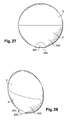
- This form of opening for dispensing product is particularly adapted to come into contact with an eyelash fringe.
- eyelashes being implanted at the edge of the eyelid, this eyelid along the contour of the eyeball, the base of the eyelashes is located on a curve.
- Separation / combing elements may extend parallel to an axis of elongation of the device and possibly parallel to a translation axis of the plate in the chimney. They are configured so as to come into engagement with the keratin fibers to separate / comb them simultaneously and / or after the application of the product to the fibers by means of the product dispensed at the level of the dispensing aperture.
- the separating / combing elements are advantageously tapered, in particular in the form of teeth or bristles, to allow efficient combing and / or separation of the keratinous fibers, and in particular eyelashes.
- the concave portion inwardly and the convex portion inwardly can be substantially superimposed, and disposed facing each other so that the dispensing aperture forms a curved slot.
- the device is moved along a path defined in the same plane substantially perpendicular to the cornea and parallel to the plane of the nose.
- This path is in particular that of the dispensing orifice which is then brought tangentially to the cornea in contact with the base of a row of eyelashes, the dispensing orifice then being moved along the row of eyelashes in the direction of their respective free end, by constraining the eyelashes against the dispensing opening.
- the displacement of the device may be done according to an iterative loop defined in one or more plane (s) substantially perpendicular (s) to the cornea and parallel (s) to the plane of the nose, depending on the desired makeup.
- this packaging and application device may comprise a gripping member, a stick of at least one cosmetic product, a fixed armature relative to the product and extending therein, the stick defining a free outer surface extending over at least a portion of the height of the frame, and a cover arranged to attach to the gripping member and cover the stick.
- the stick may be formed of a single product or alternatively have two different products or more.
- One of the products can be colored and the other intended to bring shine.
- the two products can be arranged respectively on either side of a median plane for the frame. This median plane can carry the salient elements. Such a product can be applied without any other constraint than to remove the protective cover.
- the frame can be fixed relative to the gripping member.
- This reinforcement contributes to mechanically maintain the product, which allows new possibilities in terms of formulation, including allows to use a product relatively fragile without fear that the product will not break.
- Such an armature may be flat or not, for example cylindrical or corrugated. A flat shape can provide flexibility to the frame, if any.
- the reinforcement may be perforated and / or comprise reliefs promoting the attachment of the product on the frame.
- the frame may comprise a plurality of holes, which are traversed by the product.
- the reinforcement may be integrally molded with the gripping member, for example in a thermoplastic material such as a polyolefin.
- the armature can be without contact with the cover when the latter is in place on the base, and in particular on the gripping member of the base.
- the armature may come into contact with the hood when it is in place on the base, which may allow for example to prevent the products from mixing if necessary.
- the base may comprise a filling opening, on the opposite side to the cover.
- the device may comprise a closure member fixed in the filling opening, removably or not.
- the base may have on at least a portion of its height an oblong outer cross section, but other forms are possible.
- the hood can be arranged to rest stably upside down on a horizontal flat surface. This can facilitate the reshaping of the stick.
- the device may comprise a base independent of the cover, on which the cover can be placed upside down in a stable manner.
- the product stick is advantageously fluidifiable by heat input.
- the product has, for example, a melting point of less than or equal to 60 ° C.
- a method of manufacturing such a device may comprise the steps of arranging the cover upside down and in place on the base, at least one product being poured in the fluid state through the filling opening of the base, and in particular of the gripping member of the base, the cover serving as a mold to give the product its shape during cooling.
- a method of reshaping a stick of at least one product of a device as defined above comprises the steps of positioning upside down the hood in place on the base, and heating the product for the bring to a temperature where it becomes fluid, so that the product takes on cooling the shape of the hood. The heating may be effected for example by placing the device in a microwave oven.
- the figure 1 represents a first embodiment of a device 1 for packaging and application according to the invention.
- Such a device may comprise on the one hand a base 2 and on the other hand a cover 3.
- This cover may be mounted on the base between a product covering position and a release position.
- the assembly comprising the device 1 and the cover 3 defines a cylinder whose generator in this example corresponds to a translation axis X of the cover 3 relative to the base 2, during assembly of this cover 3 on the device 1.
- the cover 3 may comprise an upper wall from which extends a peripheral skirt.
- This cover, and in particular said upper wall, may comprise a mirror (not shown) intended to facilitate product application.
- Such a base comprises a gripping member 205.
- the cover 3, and in particular said peripheral skirt, may be circumscribed to the master torque of the gripping member 205.
- a section transverse to the axis X of the present assembly an outward convex contour, for example of ovoid shape.
- the cross section is elliptical with a large Y axis.
- the gripping member 205 has a height H1, and the hood a height H2.
- the ratio of the height H1 to the sum of the heights H1 and H2, corresponding substantially to the height of the assembly in the assembled position is between 0.3 and 0.4, and preferably of the order of 1/3.
- the height H1 corresponds to the thickness of one inch.
- the gripping member is in particular configured to be gripped tightly between two fingers, for example between the thumb and the index finger.
- H1 is for example between 1 and 3 centimeters, preferably between 1.5 and 2 cm.
- the user detaches the cover 3 from the base 2, the device 1 then being in the form presented on the figure 2 .
- the cover 3 is for example retained on the base, and in particular on the gripping member of the device, by latching means 4.
- the cover 3 may also comprise an annular lip 5 engaged in force in an annular space 6 defined by the grasping organ.
- the annular space 6 is defined at a edge 7 of a side wall 8 of the gripping member.
- the side wall 8 is erected on a bottom 9 defined transversely to the axis X.
- a first outer annular skirt 10 is erected on the edge 7. This skirt has an outer periphery defined along the generatrix of the outer periphery of the cylindrical side wall 8 .
- the annular space 6 is defined between this first outer annular skirt 10 and a second inner annular skirt 11, extending along the generatrix of the cylindrical inner periphery of this lateral wall 8.
- the latching means 4 are presented in the form of a transverse bead 12 protruding outwardly from the gripping member, from the second inner annular skirt 11.
- the second inner annular skirt 11 has a height along the X axis greater than that of the outer annular skirt 10.
- the inner annular skirt 11 has two transverse beads such as 12, these two beads advantageously extend substantially parallel to the major axis Y of the ellipse formed by the outer periphery of the inner annular skirt 11.
- latching means 4 may be configured to cooperate with a complementary relief provided inside the cover 3. The axial immobility of the cover 3 relative to the base 2 is thus obtained.
- annular lip 5 is in tight engagement between the inner periphery of the first outer annular skirt 10 and an annular groove or ring 13 provided protruding from the second annular skirt 11 in the annular space 6.
- a second gadroon or annular ring may be provided.
- the hood may be devoid of relief. This double sealing cord linked to the presence of two gadroons makes it possible to have a tight tightness of the hood.
- the cover 3 assembled on the base 2 and allows to define a sealed interior volume, a static seal being provided between these two parts.
- the product contained in the set is protected vis-à-vis the external environment.
- the base 2 also comprises a chimney 14.
- This chimney is erected inside the gripping member 205, the chimney 14 being attached inside this body. Such a chimney 14 then protrudes relative to the gripping member 205.
- This chimney 14 defines a product housing, and has a dispensing opening 15 axially opposite the bottom 9.
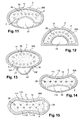
- an internal cross section of the chimney 14 is shaped "bean". Indeed, this internal cross section has a concave portion 16 inwardly and a convex portion 17 inwardly, Figure 3 .
- These concave portions 16 and convex 17 extend along a larger dimension of a cross section of the device. More particularly, these concave and convex portions generally extend along the major axis Y, and in particular on either side of this axis.
- the dispensing opening 15 then has a section substantially identical to that of the chimney 14.
- the portions 16 and 17 are vis-à-vis so that the dispensing opening forms a slot extending along a curve C.
- the portions 16 and 17 have different radii of curvature so that the width of the slit measured perpendicular to the curve C passes through a maximum in a median zone, at a distance from the ends of the portions 16 and 17.
- the inwardly concave portion 16 has a smaller radius than the convex portion 17, so that at the ends there is a small radius which makes it possible to make up the eyelashes of the corner of the eye and that in the center we have a larger width to allow filling and obtain a large volume of product.
- the chimney 14 is cylindrical generatrix parallel to the axis X.
- a side wall 18 of this chimney has an outer face having a convex profile 19 outwardly and a concave profile 20 outwardly in correspondence of respectively concave portions 16 and convex 17.
- the side wall 18 has in this example a substantially constant thickness.
- the outwardly convex profile 19, also extends substantially along the curve C. It is brought into contact with the inner periphery of the inner annular skirt 11.
- this curve C extends along the major axis Y of the ellipse formed by the cross section of the gripping member 205. There is therefore a space 21 between the outwardly concave profile 20 and the inner periphery of the side wall 8.
- a drive means 22 is arranged in part in this space 21.
- the drive means 22 comprises a push button 23 housed in the space 21 and cooperating with a product support or tray disposed inside the chimney 14 , such as a displacement of the push button along the X axis, allows a translation along this axis of the plate in the chimney 14 for product distribution via the dispensing orifice 15.
- the push button 23 is circumscribed to the master torque of the gripping member 205, and even circumscribes the master torque of the annular gadroon 13.
- the concave portion 16 can have a radius of identical curvature, and therefore superimposable to that of the convex portion towards the inside 17.
- the radius of curvature of the inwardly concave portion 16 may be greater than that of the inwardly convex portion 17.
- the outer periphery of the gripping member 205 defines a semicircle, within which is disposed the chimney 14 defining the housing for the product P.
- the inner and outer periphery of the chimney 14 is a half-ring.
- the chimney 14 has an integrally concave profile towards the inside, and is erected in a gripping member 205 having two concavities towards the outside, forming respectively two convex portions 101 and 102 inwards.
- the driving means 22 is housed in this embodiment, in the space 21 defined between the outer periphery of the side wall 18 and the inward concavity defined by the wall 8 between the two convex portions 101 and 102.
- the chimney 14 has two inwardly convex portions 111 and 112, and the gripping member 205 has a convex portion 113 inwardly.
- the convex portion 113 of the gripping member 205 is disposed facing the convex portion 111 of the chimney 14, the driving means 22 being disposed between the second convex portion 112 of the chimney 14 and the gripping member 205 .
- the chimney 14 has two inwardly convex portions 111 and 112 facing respectively two convex portions 113 and 114 towards the inside of the gripping member 205.
- a space 21 is nevertheless provided between the wall 18 and the gripping member 205 in which the bulk of the drive means 22 can be placed.
- the external cross section of the base may not be homothetic of the internal cross section of the chimney 14.
- the device comprises salient elements 26 which extend into the dispensing opening 15. Some or, as shown, all of these elements extend at a distance from an edge or free edge 25 delimiting said dispensing opening. These elements extend at a radial distance from the non-zero edge of said edge, for example between 1 mm and 20 mm.
- the projecting elements 26 may comprise teeth or pins. Such projecting elements may for example be conical. They can have a circular base diameter of the order of 1 mm. The diameter at the free end can be of the order of 0.3mm. Two consecutive protruding elements may be spaced from each other by about 1 mm.
- These salient elements may include a row of teeth.
- these projecting elements may comprise a plurality of rows of teeth, for example two, three or more. Such projecting elements can then be arranged aligned from one row to another. Alternatively, the projecting elements may be arranged offset or staggered.
- these elements are arranged in a curvilinear row or in an arc. Such elements may have a cross section of dimension decreasing from the center to at least one or both peripheral ends of the product, where appropriate along the curve C.
- the projecting elements are arranged in oval.
- the projecting elements may for example have a circular cross section.
- these elements are arranged in a perfectly straight row.
- Such elements have, for example, a cross-section of diamond shape.
- these elements are arranged alternately offset.
- these elements may be arranged a plurality of rows, such as two rows, each row comprising a tooth element located cantilevered relative to two elements of the other row.
- Such elements have for example a cross section of triangular shape.
- these elements could also be arranged in a circle or a polygonal structure. Other cross-sectional shapes could also be considered.
- Each projecting element comprises a free end 261 respectively adapted to protrude relative to a free outer surface 100 of the product.
- a dummy line connecting the free ends of the projecting elements may have a curved profile, as shown in FIG. figure 3 , or rectilinear, as shown on the figure 16 .
- these free ends may define an arc possibly coincident with the curve C.
- This arc may for example have a radius of curvature greater than that of the portion 16, and less than that of the portion 17.
- This curve can stretch in a plane transverse to an axis of elongation of the device.
- Some, or all, of the protruding elements may be at least partly surrounded by product, in use condition and possibly also in idle condition.
- the projecting elements can extend from the gripping member 205 of the base 2. These elements can be made in one piece with said gripping member. Alternatively, they can be reported in corresponding housings provided in the gripping member and fixed by any suitable means such as by fitting, screwing, latching, gluing, welding or other. These salient elements, when reported, may possibly be made of a material different from that of the base.
- these projecting elements can extend through the openings 40 formed in the product support.
- These elements can be positioned so that they extend over at least a portion of the height of the product, or over at least the entire height of the product. In other words, these projecting elements can cross the product over substantially its entire height. In particular, these projecting elements can pass through the product at two opposite portions of this product. These two opposite portions may comprise a lower portion resting on the product support and an upper portion or crown intended to come into contact with the body application surface to be made up or treated. When the device is placed on a resting surface, with the base, and in particular the bottom of the gripping member, resting on this surface, the projecting elements can extend below, through and beyond. top of the product. In other words, these elements then extend inside the product so as to emerge flush or protruding product.
- At least a portion of the projecting elements may extend substantially parallel to an axis of elongation of the device, and where appropriate substantially parallel to the axis X.
- the projecting elements 26 can extend from the chimney 14 of the base 2.
- these projecting elements can extend into the chimney. They can then stand up from a flange 140 extending from an inner wall of the chimney.
- This flange can possibly be connected to the chimney by one or more cross members 141.
- This flange, and where appropriate these crosspieces, can be made in one piece with said chimney.
- this flange 140 may be mounted on or through an open end of said chimney.
- the projecting elements 26 may be made in one piece with said flange alone or together with said chimney or may be attached in fixing position by any appropriate means such as those previously described.
- the chimney may have a substantially central portion devoid of projecting elements so as to allow, as illustrated in FIG. figure 20 , the insertion of the product support.
- Movement restriction, and in particular centering, elements 142 may be implemented to facilitate the mounting of the product support.
- Such elements may extend opposite said central portion. They can in particular form a guide rail for mounting said support.
- a guide rail may for example comprise at least one longitudinal rib. As shown, this guide rail may more precisely comprise a pair of longitudinal ribs 143. Where appropriate, a second pair of ribs disposed opposite the first pair may be provided.
- the projecting elements 26 can extend on either side of this central portion. It is then possible to distinguish two distinct groups of salient elements each comprising a plurality of salient elements, each group may for example comprise between 2 and 20 salient elements.
- the two groups may include salient elements 26 of number, nature and / or identical configuration. On the contrary, the number, nature and / or configuration of these salient elements 26 may be distinct. Such an embodiment can then make it possible to obtain a distinct makeup or treatment of the keratinous fibers according to the group of selected salient elements.
- the push button 23 has a contour and or a surface effect to facilitate its handling.
- the push button has a hollow configured to cooperate with the pulp of the tip of the thumb.
- the side wall 18 comprises guide rails 24 to cooperate with the push button 23.
- the push button is in a median position between a free edge of the second inner skirt 11 and the dispensing opening, the product presented here in the form of a solid cake is erected partly outside the opening of distribution 15.
- the push button 23 is movable relative to the chimney 14 between a low position and a high position.
- a free axial end of the push button In the low position, a free axial end of the push button, relative to its translation axis X, protrudes from the base 2 and is located near the free edge of the second inner skirt 11.
- the free axial end In the up position, the free axial end is disposed substantially in the plane of the dispensing opening 15, and more particularly at the free edge 25 of the side wall 18 of the chimney 14.
- the push button 23 has a screen wall 27 which gradually leaves the base when it is brought from the low position to the high position.
- This screen 27 is initially hidden in the base 2 in the low position.
- This screen 27 comprises, as can be seen in the exploded views of Figures 5 and 6 a lug 29 erected transversely to this screen, at a free end opposite the free end of the push button configured to be manipulated. Even in the high position, the push button may extend to a lower height than the free end of the projecting elements.
- the lug is configured to pass through a groove 28 formed in an axial portion 30 of the side wall 18.
- the groove 28 is formed in the concave face towards the outside 20.
- the groove 28 guides the sliding of the push button on along the chimney 14.
- the groove 28 is formed in the portion of the chimney 14 contained in the base. It is masked both by the base and the push button 23, in particular the screen 27 of the push button 23.
- the groove 28 opens at an axial end opposite to that defining the dispensing opening 15.
- the lug 29 can be inserted into the groove 28 by translation along the groove 28.
- the lug 29 has an end 31 engaged in an orifice 32 formed in a rod 33.
- This rod 33 can be raised from a perforated bottom 34 of the plate 35 on which the product is disposed.
- the rod 33 is erected in a direction opposite to the displacement of the plate going from the low position to the high position along the X axis.
- the end 31 can be snapped, or tight fitting.
- the engagement can be flexible, the only mobility tolerated being axial along the X axis.
- the push button 23 and the plate 35 can be made in one piece.
- This piece may then have a "U" shape comprising a connecting arm to the product support, a flange protruding from the device through the groove 28 and the wheel, for example facing in the present example of the concave portion to 20.
- Such a piece can be inserted into the groove 28 by translation along the groove 28.
- the rod 33 inside the chimney, is located in the portion hidden by the base 2 when the push button 23 is in the lower position.
- the groove 28 forms in cooperation with the bottom 9 a first abutment B1 of translation of the push button relative to the chimney. The low position is thus determined.
- the outer periphery of the plate has a periphery slightly larger than the cross section of the inner periphery of the side wall. 18 so as to result in a tight fit.
- the inner periphery of the wall lateral is slightly flared towards its dispensing opening 15.
- the plate 35 has an annular lip 36 to define the seat for receiving the product to be dispensed.
- This annular lip 36 may come into sealed elastic contact with the inner periphery of the side wall, in particular in the lower position.
- Such a plate 35 may also comprise a plurality of spacers 42 connecting two portions opposite the bottom 34.
- spacers may for example be three in number.
- the fins can be raised from these spacers. Such fins may then protrude relative to the bottom 34. These fins may possibly stand substantially parallel to each other.
- a stiffening means 43 of this support for example in the form of a beam, can connect these spacers. If necessary, openings may be left on either side of this beam, between said beam and the bottom 34.
- these fins may for example be four in number. They may be arranged so that two adjacent fins extend in respective secant planes. In particular, these fins can define between them an acute angle for example of the order of 25 °. Furthermore, a first and a third fin may extend parallel to each other, as well as a second and a fourth fin. Such an arrangement ensures a good anchoring of the product on its support.
- the groove 28 has a second stop B2 axially opposite the first stop B1, this second stop being located below the level of the annular lip 36 when the push button is in the lower position.
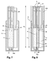
- the product height H3 before the first use can correspond to the distance between the plate 35 in the low position and the plane of the free edge 25.
- This height H3 is, for example, of the order of 3 cm.
- the total height H4 between the bottom 9 of the base and the free edge 25 of the chimney 14 when the latter is mounted is substantially equal to twice the height H3.
- the ratio R of the height H3 to the height H4 is of the order of 0.5, as represented on the Figures 7 and 8 .
- the upper lip of the plate 35 being clamped in the chimney 14, it prevents the push button from sliding by gravity towards its upper position.
- the hood 3 is put in place.
- a shutter 41 arranged inside the chimney to plug the housing and shape the free end of the hot-poured product in its housing.
- the shutter 41 has gripping means protruding into the hood to facilitate its removal during the first use.
- the shutter 41 can be made in one piece with the cover 3 or be brought into fixing position in this cover 3.
- the cover 3, and optionally the shutter 41 may comprise positioning means 410 of the projecting elements.
- Such means are particularly useful for correctly positioning the projecting elements when filling the device product. They may comprise a plurality of housings adapted to receive at least partly the projecting elements, and in particular their respective free end. These housings can keep these free ends out of contact with the product when the latter is poured.
- the projecting elements may thus be in protruding configuration relative to the product during casting and at the end of casting.
- an insert member provided with said positioning means 410 may be provided.
- This element can be connected to the hood. It may for example comprise a plate, if necessary flexible, or a foam. This element may be locally perforated so as to form a plurality of housing for the salient elements. Such an insert can then extend between an inner wall of the hood and the cast product.
- the distance between the two abutments B1 and B2, minus the axial height of the lug 29 at the groove 28, defines the permissible axial stroke of the plate 35 in the chimney and corresponds substantially to the distance between the low position and the high position.
- the end of the fins of the plate 35 is substantially at the level of the dispensing opening 15.
- a product permeable member may be disposed at the dispensing opening 15.
- This permeable member may be porous, fibrous, alveolar or pierced with multiple channels.
- the flow and the distribution of the product at the level of the opening can be modified.
- a more liquid formula can be distributed.
- the tray is intended to be in sealing contact with the chimney 14 over the entire height between the low position and the high position.
- the free edge 25 may also include separating / combing elements 26.
- the gripping member 2, the cover 3, the chimney 14, the push button 23 and the plate 35 are for example obtained from molding. They are for example respectively made of polyethylene, polypropylene, polyamides, polyacetal, polystyrene, polyoxymethylene (POM), ABS or other.
- the plate 35 and the chimney 14 will not be made of the same material to avoid friction between two parts at the same coefficient of friction.
- the displacement of the plate 35 relative to the chimney 14 can be fluid and without causing a grinding noise.
- the device 1 according to the invention is particularly configured for the application of a pasty product on the eyelashes.
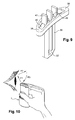
- This device is innovative for users, as well as the gesture of use. Indeed, the use of such a device is preferably done by bringing the device into contact with the base of the eyelashes, having the major axis Y substantially tangential to the cornea, the path that the user imposes on the device to obtain the The desired coating of its eyelashes follows a loop in a movement whose components are defined in a plane perpendicular to the cornea and parallel to the bridge of the nose. The movement breaks down in three stages, and corresponds to the F1, F2 and F3 displacements schematized on the Figure 10 .
- the user preferably has the curve C defined by the dispensing opening 15 substantially parallel to the curve formed by the free border of the eyelid at which the eyelashes are implanted.
- the edges defined at the junction between the portions 16 and 17 respectively allow an improved treatment of the edges of a row of eyelashes, in particular for the coating of the eyelashes of the inner and outer edge of the eye, including spot retouches.
- the movements of the device are always performed in the plane perpendicular to the cornea and parallel to the edge of the nose, but in this case, the major axis Y is disposed in this plane.
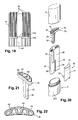
- the Figures 23 to 38 represent a second embodiment of a device 1 'for packaging and applying at least one cosmetic product, including care, to the keratinous fibers.
- This second embodiment differs in particular from the first embodiment in that the gripping member and the chimney are one and in that it is devoid of drive means and in particular push button. Moreover, the product support referred to as a tray with reference to the first embodiment, will be called, in this second embodiment, internal reinforcement.
- the packaging and application device 1 'represented on the Figures 23 to 38 comprises a base 2 'on which can be fixed a protective cover 3'.
- the base 2 ' comprises a gripping member 205' that the user can enter.
- the gripping member 205 ' has a filling opening 200', situated on the side opposite the cover 3 ', closed by a bottom or closure member 9'.
- the device 1 ' also comprises an internal armature 35' possibly fixed relative to the gripping member 205 '.
- This reinforcement is for example integrally molded with the gripping member 205 ', for example a thermoplastic material.
- the bottom 9 ' can also be fixed in various ways on the gripping member 205', for example by friction, snapping or screwing.
- the bottom 9 ' may be removable or not.
- the bottom 9 ' is removable and comprises an annular sealing lip 90' which is sealingly applied to a cylindrical surface 201 'of revolution, the filling opening 200'.
- the armature 35 aims to mechanically maintain the product, which allows new possibilities in terms of formulation, including allows to use a relatively fragile product without fear that the use of the product will break. Such an armature can thus be fixed relative to the product and extend therein.
- This armature 35 ' may be flat or not, for example cylindrical or corrugated.
- a flat shape can provide flexibility to the frame, if any.
- the armature 35 ' has a flattened shape with a thickness e which can for example decrease slightly in the direction of its upper edge or wafer 37', which may have a front view of a substantially semicircular shape.
- the gripping member 205 ' may comprise an edge or free edge 25' possibly extended by a recess to allow the cover 3 'to register in the continuity of the outer surface of the gripping member 205 '.
- the gripping member 205 has, over at least a portion of its height, an oblong, in particular substantially elliptical, external cross section, as can be seen in the drawings.
- Figures 25 and 26 for example.
- the armature 35 ' can be connected to the gripping member 205' by amounts 350 'diametrically opposed, the armature 35' being in the example considered flattened in a plane containing the major axis of the cross section of the base 2 '.
- the armature 35 ' may comprise at its base a recess 351', as illustrated in FIG. figure 24 , in the extension of the filling opening.
- the armature 35 ' is perforated in the example, having a plurality of holes 38' possibly traversed by the product so as to improve the anchoring of a stick of a product P on the armature 35 '.
- the armature 35 'could include reliefs promoting the attachment of the product on the frame.
- the projecting elements supported by the armature 35 ' are inscribed in the dispensing opening 15' defined by the free edge 25 '.
- these elements extend away from this free edge.
- these projecting elements are arranged on a wafer 37 'of the armature 35'.
- This slice 37 ' may define an anchoring surface for the curved projecting elements, for example in a semicircle.
- Such elements can be made in one piece with this frame. Alternatively, they can be reported on this frame and fixed by any appropriate means.
- the projecting elements 26 ' may comprise at least one row of teeth arranged in a curved profile. These salient elements 26 'may for example extend over at least a quarter of circle, better a third of a circle or even a half of a circle. Such projecting elements may extend radially relative to said armature 35 '. Such projecting elements 26 'can thus point in respective distinct directions. These projecting elements 26 'can in particular extend along an elongation plane of the device 1'.
- the projecting elements 26 ' may comprise at least one row of teeth whose free ends 261' extend at the same height. Such free ends may be arranged in a rectilinear profile.
- the projecting elements 26 ' may have, at least for some or all of them, a distinct length.
- the projecting elements 26 'at the center, or at the top, of the wafer 37' may have a shorter length than the peripheral teeth. More precisely, this length may decrease from the center, or vertex, of the armature towards the periphery of this armature.
- the projecting elements may thus be larger or larger as one approaches the free edge 25 '.
- Such salient elements may point in the same direction. In other words, these projecting elements 26 'can extend substantially parallel to each other.
- the projecting elements 26 ' extend at least partly in the product stick. More specifically, these projecting elements 26 'comprise respective free ends 261' adapted to be flush or, in this case, to project relative to the free outer surface 100 'of the product.
- the stick P extends above the base 2 'inside the cover 3' but it is not beyond the scope of the present invention when the product stick P also extends inside the base 2 ', and in particular of the gripping member 205', at least before the first use of the device 1.
- the filling opening 200 ' may be formed inside a base 202' of the gripping member 205 ', having a lower end 203' situated in the same plane perpendicular to the longitudinal axis of the device 1, This allows the user to place it upright on a flat horizontal surface.
- the base 202 ' has for example an outer surface 204' of cylindrical revolution about the axis X, as can be seen in particular in the figure 25 .
- the product stick P may have various shapes and for example an oblong transverse section elongated along a major axis X 1 , the dimension d 1 of the stick P along the axis X 1 being for example such that the ratio d 1 / d 2 , where d 2 denotes the dimension along the minor axis X 2 perpendicular to X 1 , being between 4 and 1, this range of values being of course in no way limiting.
- the product stick P may define a free outer surface 100 'extending over at least a portion of the height of the frame. This surface can be without contact with a wall covering, during use of the device. In other words, the product stick P covers the armature 35 'over a height h while having a free outer surface 100' during use, which may vary with the wear of the product stick. Thus, the product can be applied without any other constraint than to remove the protective cover.
- the product or products may be intended for application to keratinous fibers.
- This product can be poured into the device through the filling opening 200 ', the bottom 9' being removed and the cover being in place on the base 2 ', the device 1' being upside down.
- Filling with the cover 3 'in place is suitable when the adhesion of the product on the cover 3' is low enough to prevent damage to the product stick P at the first removal of the cover 3 '.
- the cover 3 ' may optionally be made of a material which reduces the adhesion of the product or has undergone a surface treatment which produces the same effect.
- This cover 3 ' may comprise positioning means comprising for example a plurality of housings, or recesses, in which the projecting elements may extend in particular during casting of the product.
- positioning means comprising for example a plurality of housings, or recesses, in which the projecting elements may extend in particular during casting of the product.
- an insert such as a flexible plate or a foam, provided with said positioning means can be implemented.
- the product is poured into a mold above which the base 2 'is placed upside down, for example a mold made of silicone or any other material making it possible to obtain a mold release without damaging the product stick. P.
- the product can be formulated to be easily fluidifiable. This can allow the user to reshape the application surface after consuming a portion of the product, by positioning the device 1 'upside down and exposing the product, hood in place, to a heat source, by example within a microwave oven.
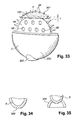
- the cover 3 ' can be made, as illustrated in FIG. figure 34 , with a 300 'summit flattened.
- the cover is thus arranged to rest stably upside down on a horizontal flat surface. This can facilitate the reshaping of the product stick.
- a base 301 ' can be used, this base 61 being arranged to maintain vertical, hood down, the device 1'.
- the reshaping of the application surface makes it possible to have a product stick P matching the shape of the inside surface of the cover, as and when the product is consumed, as illustrated in FIGS. Figures 31 to 33 .
- the device 1 comprises a product stick comprising two different products P 1 and P 2 , occupying for example substantially each half of said stick.
- the two products can be arranged respectively on either side of a median plane for the frame.
- Mon products can be colored and the other intended to provide gloss, the two products can be applied one after the other, for example.
- the armature 35 ' may be identical to that of the example described above.
- the product may be poured by the user himself, if necessary, into the device, this product being for example produced from one or more components which are mixed in proportions chosen by the user, depending on the desired result.
- the positioning means provided for accommodating the projecting elements may be of such length that the inner wall of the cover, or of the insert, is able to abut against said wafer 37 'when the cover 3' is put in place on the base 2 ', and this so as to prevent the products P1 and P2 do not mix.
- the hood or the insert act as a partition member of the cast products.
- the device may optionally comprise, as illustrated in FIG. figure 37 , an applicator 101 ', for example acting as closure member, this applicator 101' may include an applicator member 102 'which is housed in the base 2' in the absence of use. In particular, this applicator member can be received in a housing formed in the gripping member 205 '.
- This application member 102 'can for example be used for finishing operations and may comprise a felt tip, a flocked tip, a brush, a foam, a brush, a comb, among others.
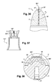
- the Figures 39 and 40 represent a third embodiment of a device 1 "for packaging and applying at least one cosmetic product, including care, to the keratinous fibers.
- This third embodiment differs in particular from the first embodiment in that the device 1 "comprises a drive means 22" comprising a wheel 23 “rotatably mounted on the chimney 14".
- the chimney 14" can be used as a gripping member 205 “during the rotation of the wheel 23". A hand of the user can thus come into engagement with the wheel 23 "and his other hand can come into contact with the chimney 14" to hold it fixed during the rotation imposed on said wheel.
- the knob 23 may be integral with a threaded rod or screw, which rod is engaged with the product and may also form a projecting element 26 'thus extending through the dispensing opening 15". It can then occupy a protruding position relative to the free edge 25 "as well as relative to the free outer surface 100" of the product.
- This projecting element can thus be integral, in particular in rotation, with the wheel 23 ", and projecting elements 26" can also be raised from the chimney 14 "of the base 2".
- the product support 35 may comprise a plate carrying a stick of product P. These elements then pass through the apertures 40" of the plate 35 "and the product P.
- a connecting member 39 "supporting the plate 35” may also be provided.
- this member can connect the rod 26 "and the plate 35".
- This member may comprise a sleeve 390 "internally coated with a thread adapted to cooperate with the complementary thread of the rod 26". Such a member is then adapted to transform a rotational movement of the rod 26 "imposed on the wheel 23" in an axial displacement of the plate 35 ", and thus the product P relative to the chimney 14".
- the structure and mode of operation of such device are further described in the document FR-2 750 022 , the contents of which are hereby incorporated by reference.
- the figure 41 represents an alternative embodiment of the third embodiment of the packaging and application device according to the present invention.
- the device may comprise two distinct product housings receiving identical or different products P1 and P2.
- the term "different" includes products of identical composition but of distinct consistency.
- the product P1 may be a product in stick form while the product P2 may be a fluid product.
- a second product housing 230 may for example be provided in the knob 23".
- Such a housing can be annular.
- the knob 23 may comprise a product outlet 231".
- the projecting elements 26 can in turn be traversed internally by a product distribution channel 262".
- This channel may extend along an axis of elongation of the projecting elements. In other words, this channel may extend from the base 260 "of the projecting elements to the free end 261" of these projecting elements.
- the base 260 “then comprises a product supply port 2600", adapted to be placed in fluid communication with the outlet orifice 231 "of the wheel while the free end 261” comprises a product dispensing orifice 2610 ". ".
- a cover 3 “comprising a shutter 41” may be provided so as to come in position mounted on the base 2 "in the closed position of the dispensing orifice 2610".
- this shutter 41 may include protrusions capable of covering or to be inserted into the respective dispensing orifices 2610". Such prominences can again serve as positioning means for the projecting elements 26 "during the pouring of the product In this nonlimiting embodiment, these protrusions extend from an insert element in the cover 3".
- Locating means may be provided, for example on the wheel 23 "and / or on the chimney 14", to indicate to the user what degree of rotation it must impose on the wheel 23 "in order to place the outlet orifice product 231 "of the wheel vis-à-vis the supply port 2600" of at least one of the projecting elements.
- These tracking means may include visual indications, such as lines or pictograms, respectively provided on the wheel 23 "and the chimney 14", to be placed vis-à-vis (not shown).
- these means of identification may include nipples 232 ", for example provided on a wall of the wheel facing the chimney, adapted to cooperate with corresponding recesses formed on said chimney, or vice versa.
- these locating means may be related to the configuration of the device.
- the device may have a cross section of elongated shape, such as oval or elliptical.
- the product outlet ports 231 "and the product supply ports 2600" can fluidly communicate when the wheel 23 "and the chimney 14" have a similar orientation so that their outer walls extend. in the continuity of one another.
- the device can go from a position of communication of the orifices to a non-communication position of said orifices when the wheel 23 "is rotated 180 ° relative to the chimney 14", and vice versa.
- the dispensing aperture 15 "extends over a surface strictly greater than that defined by the dispensing orifice 2610", in particular at least twice as much, five times, ten times, a hundred times, or more.
- the wheel 23 may comprise a flexible wall that can be compressed by the user in order to raise the product P2 through the dispensing channel 262".
- a piston type drive means may be implemented (not shown).
- This drive means may comprise a plate forming a bottom wall of the product housing 230. Such a plate may be mounted in sealed friction contact in the wheel 23 ". With each movement of this plate towards the product outlet orifices 231 ", by sliding or screwing for example, the product P2 can be distributed through the dispensing orifices 2610".
- the product P2 can be distributed by gravity effect by returning the device 1 ".
- the invention is not limited to the embodiments which have just been described. Indeed, for example, it is also possible to provide salient elements according to the invention in other conventional product distribution mechanisms in stick form and / or in other forms of stick.
Landscapes
- Closures For Containers (AREA)
- Cosmetics (AREA)
Applications Claiming Priority (1)
| Application Number | Priority Date | Filing Date | Title |
|---|---|---|---|
| FR0851203A FR2927783A1 (fr) | 2008-02-26 | 2008-02-26 | Dispositif de conditionnement et de distribution d'un produit cosmetique |
Publications (1)
| Publication Number | Publication Date |
|---|---|
| EP2095738A1 true EP2095738A1 (de) | 2009-09-02 |
Family
ID=39808925
Family Applications (1)
| Application Number | Title | Priority Date | Filing Date |
|---|---|---|---|
| EP09152245A Withdrawn EP2095738A1 (de) | 2008-02-26 | 2009-02-06 | Vorrichtung zur Verpackung und Verteilung eines Kosmetikprodukts |
Country Status (4)
| Country | Link |
|---|---|
| US (1) | US20090214283A1 (de) |
| EP (1) | EP2095738A1 (de) |
| JP (1) | JP2009201993A (de) |
| FR (1) | FR2927783A1 (de) |
Cited By (1)
| Publication number | Priority date | Publication date | Assignee | Title |
|---|---|---|---|---|
| EP2329741A1 (de) * | 2009-12-04 | 2011-06-08 | GEKA GmbH | Kosmetikapplikator, insbesondere Mascara-Applikator, sowie Pigmentmassemine hierfür und Kosmetikprodukt |
Families Citing this family (9)
| Publication number | Priority date | Publication date | Assignee | Title |
|---|---|---|---|---|
| FR2963217B1 (fr) * | 2010-07-28 | 2012-09-21 | Oreal | Dispositif de conditionnement et d'application d'au moins une composition cosmetique solide |
| US9301590B2 (en) | 2013-10-08 | 2016-04-05 | International Cosmetic Suppliers Ltd | Retractable cosmetic pencil |
| US9538830B2 (en) | 2015-03-31 | 2017-01-10 | Dana Rae, LLC | Eyeliner with application guide cap |
| EP3092917A1 (de) * | 2015-05-12 | 2016-11-16 | Enrica Monica Ancorotti | Verfahren zur herstellung einer mascaraverpackung |
| WO2018191218A1 (en) * | 2017-04-11 | 2018-10-18 | Ojip, Llc | Device for applying and removing nail polish |
| JP7257138B2 (ja) * | 2018-12-14 | 2023-04-13 | 三菱鉛筆株式会社 | 塗布具 |
| US12446676B2 (en) | 2019-04-08 | 2025-10-21 | Kaz Europe Sárl | Handle for nail polish applicator |
| US11406168B2 (en) * | 2019-11-04 | 2022-08-09 | Briana, Llc | Solid product dispenser |
| US12458128B2 (en) * | 2022-05-20 | 2025-11-04 | Alycia Aileen Allen | Infused grooming apparatus |
Citations (16)
| Publication number | Priority date | Publication date | Assignee | Title |
|---|---|---|---|---|
| US2007245A (en) | 1934-06-22 | 1935-07-09 | Gimonet Alexandre | Cosmetic device |
| GB2159045A (en) | 1984-03-06 | 1985-11-27 | Geka Brush Georg Karl Gmbh | Applicator for fluid, paste or powder-like materials |
| DE3704936A1 (de) | 1987-02-17 | 1988-08-25 | Schwan Stabilo Schwanhaeusser | Haarfaerbeeinrichtung |
| FR2632834A1 (de) | 1988-06-20 | 1989-12-22 | Mitsubishi Pencil Co | |
| EP0697181A2 (de) * | 1994-08-16 | 1996-02-21 | UHU GmbH | Klebstift mit kolbenförmiger Haltevorrichtung für die Stiftmasse |
| FR2727608A1 (fr) | 1994-12-06 | 1996-06-07 | Oreal | Distributeur pour un produit de consistance liquide a pateuse |
| FR2750022A1 (fr) | 1996-06-19 | 1997-12-26 | Oreal | Distributeur de produit a organe de manoeuvre rotatif et procede de fabrication |
| US5937864A (en) | 1998-09-25 | 1999-08-17 | Diaz; Donne'j. | Hair coloring applicator with mixing chamber |
| FR2865196A1 (fr) | 2004-01-20 | 2005-07-22 | Oreal | Kit comportant deux recipients et un applicateur |
| FR2881343A1 (fr) | 2005-01-31 | 2006-08-04 | Oreal | Composition cosmetique solide de maquillage et/ou de soin |
| FR2888735A1 (fr) | 2005-07-22 | 2007-01-26 | Oreal | Dispositif pour le conditionnement et l'application d'un produit |
| FR2892901A1 (fr) | 2005-11-09 | 2007-05-11 | Oreal | Dispositif de conditionnement et d'application d'un produit sur des fibres keratiniques |
| WO2007066764A1 (ja) | 2005-12-09 | 2007-06-14 | Sakura Color Products Corporation | 毛染め容器、並びに、毛染め具 |
| FR2895252A1 (fr) | 2005-12-22 | 2007-06-29 | Oreal | Composition de soin et/ou de conditionnement des fibres keratiniques |
| FR2895248A1 (fr) | 2005-12-22 | 2007-06-29 | Oreal | Composition cosmetique de nettoyage et/ou lavage |
| US20070251537A1 (en) * | 2005-08-29 | 2007-11-01 | L'oreal | Product application device |
Family Cites Families (4)
| Publication number | Priority date | Publication date | Assignee | Title |
|---|---|---|---|---|
| ES2220921T3 (es) * | 1994-12-06 | 2004-12-16 | L'oreal | Distribuidor para un producto de consistencia liquida a pastosa equipado con un elemento tubular de aplicacion. |
| US7534062B2 (en) * | 2004-01-20 | 2009-05-19 | L'oreal | Kit comprising two receptacles and an applicator |
| US20060193801A1 (en) * | 2005-01-31 | 2006-08-31 | L'oreal | Solid cosmetic composition textured with an organic copolymer |
| US7883286B2 (en) * | 2005-11-09 | 2011-02-08 | L'oreal | Beauty care product application device |
-
2008
- 2008-02-26 FR FR0851203A patent/FR2927783A1/fr active Pending
-
2009
- 2009-02-06 EP EP09152245A patent/EP2095738A1/de not_active Withdrawn
- 2009-02-25 JP JP2009042824A patent/JP2009201993A/ja active Pending
- 2009-02-26 US US12/393,667 patent/US20090214283A1/en not_active Abandoned
Patent Citations (16)
| Publication number | Priority date | Publication date | Assignee | Title |
|---|---|---|---|---|
| US2007245A (en) | 1934-06-22 | 1935-07-09 | Gimonet Alexandre | Cosmetic device |
| GB2159045A (en) | 1984-03-06 | 1985-11-27 | Geka Brush Georg Karl Gmbh | Applicator for fluid, paste or powder-like materials |
| DE3704936A1 (de) | 1987-02-17 | 1988-08-25 | Schwan Stabilo Schwanhaeusser | Haarfaerbeeinrichtung |
| FR2632834A1 (de) | 1988-06-20 | 1989-12-22 | Mitsubishi Pencil Co | |
| EP0697181A2 (de) * | 1994-08-16 | 1996-02-21 | UHU GmbH | Klebstift mit kolbenförmiger Haltevorrichtung für die Stiftmasse |
| FR2727608A1 (fr) | 1994-12-06 | 1996-06-07 | Oreal | Distributeur pour un produit de consistance liquide a pateuse |
| FR2750022A1 (fr) | 1996-06-19 | 1997-12-26 | Oreal | Distributeur de produit a organe de manoeuvre rotatif et procede de fabrication |
| US5937864A (en) | 1998-09-25 | 1999-08-17 | Diaz; Donne'j. | Hair coloring applicator with mixing chamber |
| FR2865196A1 (fr) | 2004-01-20 | 2005-07-22 | Oreal | Kit comportant deux recipients et un applicateur |
| FR2881343A1 (fr) | 2005-01-31 | 2006-08-04 | Oreal | Composition cosmetique solide de maquillage et/ou de soin |
| FR2888735A1 (fr) | 2005-07-22 | 2007-01-26 | Oreal | Dispositif pour le conditionnement et l'application d'un produit |
| US20070251537A1 (en) * | 2005-08-29 | 2007-11-01 | L'oreal | Product application device |
| FR2892901A1 (fr) | 2005-11-09 | 2007-05-11 | Oreal | Dispositif de conditionnement et d'application d'un produit sur des fibres keratiniques |
| WO2007066764A1 (ja) | 2005-12-09 | 2007-06-14 | Sakura Color Products Corporation | 毛染め容器、並びに、毛染め具 |
| FR2895252A1 (fr) | 2005-12-22 | 2007-06-29 | Oreal | Composition de soin et/ou de conditionnement des fibres keratiniques |
| FR2895248A1 (fr) | 2005-12-22 | 2007-06-29 | Oreal | Composition cosmetique de nettoyage et/ou lavage |
Cited By (2)
| Publication number | Priority date | Publication date | Assignee | Title |
|---|---|---|---|---|
| EP2329741A1 (de) * | 2009-12-04 | 2011-06-08 | GEKA GmbH | Kosmetikapplikator, insbesondere Mascara-Applikator, sowie Pigmentmassemine hierfür und Kosmetikprodukt |
| CN102090776A (zh) * | 2009-12-04 | 2011-06-15 | 格卡有限公司 | 涂抹器、尤其是睫毛膏涂抹器、涂抹器用颜料笔芯和化妆用产品 |
Also Published As
| Publication number | Publication date |
|---|---|
| JP2009201993A (ja) | 2009-09-10 |
| FR2927783A1 (fr) | 2009-08-28 |
| US20090214283A1 (en) | 2009-08-27 |
Similar Documents
| Publication | Publication Date | Title |
|---|---|---|
| EP2095738A1 (de) | Vorrichtung zur Verpackung und Verteilung eines Kosmetikprodukts | |
| EP1913835B1 (de) | Vorrichtung zur Verpackung und Anwendung | |
| EP0861617B1 (de) | Vorrichtung zum Verpackung und Auftragen von Schminkprodukten auf keratinische Fasern | |
| EP1839524B1 (de) | Behälter und Auftragelement | |
| FR2939289A1 (fr) | Dispositif de conditionnement et de distribution d'un produit cosmetique. | |
| EP0978241B1 (de) | Vorrichtung zum Auftragen von Schminkprodukten mit einer Bürste, Verfahren zu dessen Herstellung und Auftragseinheit mit einer solchen Vorrichtung | |
| FR3064459A1 (fr) | Applicateur cosmetique | |
| WO2001005274A1 (fr) | Peigne pour l'application d'un produit sur des fibres keratiniques, ensemble d'application ainsi equipe et utilisation de cet ensemble | |
| EP1142504A1 (de) | Auftragsvorrichtung zum Aufbringen eines Produktes auf einen Untergrund und damit ausgerüstete Auftragseinheit | |
| FR2920076A1 (fr) | Dispositif de conditionnement et d'application pour composition cosmetique | |
| FR2909270A1 (fr) | Organe d'essorage et dispositif comportant un tel organe | |
| FR2963217A1 (fr) | Dispositif de conditionnement et d'application d'au moins une composition cosmetique solide | |
| EP1785055B1 (de) | Vorrichtung zur Verpackung und zum Auftragen eines Produktes auf keratinische Fasern | |
| FR2976461A1 (fr) | Dispositif pour l'application en meches d'un produit capillaire | |
| EP2138068B1 (de) | Verpackungseinheit, insbesondere für eine kosmetische Zubereitung, mit einer bewegbaren Wischervorrichtung | |
| EP1428455B2 (de) | Applikator, insbesondere für Kosmetik | |
| FR2779039A1 (fr) | Boitier contenant un produit delitable, equipe d'un element d'application | |
| FR2926446A1 (fr) | Applicateur pour la reception et l'application d'un produit, notamment d'un produit cosmetique, du type a cuillere | |
| EP2135524A1 (de) | Verpackung für ein kosmetisches Produkt | |
| EP2140778A1 (de) | Vorrichtung zur Verteilung von Kosmetik-Accessoires und entsprechendes Vorbereitungsverfahren | |
| FR2962890A1 (fr) | Applicateur a membrane | |
| FR2888735A1 (fr) | Dispositif pour le conditionnement et l'application d'un produit | |
| FR3092734A1 (fr) | Procédé de maquillage et/ou de soin des fibres kératiniques des sourcils conditionnement et d’application d’un produit cosmétique en stick | |
| FR3059214A1 (fr) | Kit de realisation d'un ensemble de conditionnement et d'application d'un produit, notamment cosmetique | |
| FR3085828A1 (fr) | Applicateur pour l'application d'un produit capillaire, notamment d'un produit cosmetique de coloration ou de decoloration |
Legal Events
| Date | Code | Title | Description |
|---|---|---|---|
| PUAI | Public reference made under article 153(3) epc to a published international application that has entered the european phase |
Free format text: ORIGINAL CODE: 0009012 |
|
| AK | Designated contracting states |
Kind code of ref document: A1 Designated state(s): AT BE BG CH CY CZ DE DK EE ES FI FR GB GR HR HU IE IS IT LI LT LU LV MC MK MT NL NO PL PT RO SE SI SK TR |
|
| AX | Request for extension of the european patent |
Extension state: AL BA RS |
|
| 17P | Request for examination filed |
Effective date: 20100302 |
|
| 17Q | First examination report despatched |
Effective date: 20100325 |
|
| AKX | Designation fees paid |
Designated state(s): AT BE BG CH CY CZ DE DK EE ES FI FR GB GR HR HU IE IS IT LI LT LU LV MC MK MT NL NO PL PT RO SE SI SK TR |
|
| STAA | Information on the status of an ep patent application or granted ep patent |
Free format text: STATUS: THE APPLICATION IS DEEMED TO BE WITHDRAWN |
|
| 18D | Application deemed to be withdrawn |
Effective date: 20110427 |