EP2095878B1 - Duschkopf und zugehörige Düsen - Google Patents
Duschkopf und zugehörige Düsen Download PDFInfo
- Publication number
- EP2095878B1 EP2095878B1 EP09001638A EP09001638A EP2095878B1 EP 2095878 B1 EP2095878 B1 EP 2095878B1 EP 09001638 A EP09001638 A EP 09001638A EP 09001638 A EP09001638 A EP 09001638A EP 2095878 B1 EP2095878 B1 EP 2095878B1
- Authority
- EP
- European Patent Office
- Prior art keywords
- spray device
- nozzles
- pins
- shower spray
- water
- Prior art date
- Legal status (The legal status is an assumption and is not a legal conclusion. Google has not performed a legal analysis and makes no representation as to the accuracy of the status listed.)
- Active
Links
Images


Classifications
-
- B—PERFORMING OPERATIONS; TRANSPORTING
- B05—SPRAYING OR ATOMISING IN GENERAL; APPLYING FLUENT MATERIALS TO SURFACES, IN GENERAL
- B05B—SPRAYING APPARATUS; ATOMISING APPARATUS; NOZZLES
- B05B1/00—Nozzles, spray heads or other outlets, with or without auxiliary devices such as valves, heating means
- B05B1/14—Nozzles, spray heads or other outlets, with or without auxiliary devices such as valves, heating means with multiple outlet openings; with strainers in or outside the outlet opening
- B05B1/18—Roses; Shower heads
- B05B1/185—Roses; Shower heads characterised by their outlet element; Mounting arrangements therefor
Definitions
- the present invention relates to a shower spray device and to a particular type of nozzle for delivering water intended for this spray device.
- shower spray devices of known type generally comprise a water distribution chamber in fluid communication with at least one inlet and with a plurality of outlet nozzles for water delivery. Some embodiments are also provided with intakes to allow suction of a certain quantity of air into the distribution chamber and allow a certain aeration of the delivered water.
- shower spray devices are currently being studied in terms of appearance and the type of jet requested.
- spray devices having a design with simple clean-cut lines are generally popular, as well as spray devices that produce a "rain" type jet, with or without aeration of the water delivered.
- the problem arises of ensuring even distribution of the water to all the delivery nozzles and optimal peripheral seal, above all in view of the fact that, when the dimensions increase, the elastic sealing rings can have considerable constructional tolerances even within a same production batch, or even a non-uniform modulus of elasticity along various portions of the same ring.
- Patent applications n. WO 2007/113863 A and n. US 2007/200013 Al both disclose shower heads according to the preamble of claim 1, i.e. shower heads having a lower plate, in which a plurality of water delivery nozzles are mounted, and an upper plate in which an inlet for the water supply is provided. Screw means allow to clamp an elastic sealing element between the two plates.
- An object of the present invention is to propose a shower spray device which can be produced with large surface dimensions, and therefore with a high number of delivery nozzles, ensuring at the same time uniform water distribution to all the nozzles and excellent peripheral seal of the distribution chamber, regardless of the characteristics of the sealing ring used and/or of the dimensions of the spray device.
- Another object of the present invention is to propose a shower spray device of the aforesaid type which can be produced with a particularly thin section and large surface extension.
- a further object of the present invention is to propose a shower spray device of the aforesaid type which in any case has a particularly simple construction and therefore which can be produced at limited costs.
- a shower spray device including at least one lower plate, in which a plurality of water delivery nozzles are mounted, at least one upper plate, in which at least one inlet for the water supply is formed, at least one elastic sealing element, interposed between the two plates, to delimit therewith a chamber for distributing water to the nozzles, and screw means for clamping the elastic sealing element between the two plates.
- the screw means include a plurality of threaded pins having at least one axial duct with an outlet open towards the outside to allow water delivery and at least one transverse duct to place the distribution chamber in fluid communication with the axial duct for water delivery.
- the threaded pins are inserted in through holes of the lower plate and are provided with a head portion suitable to abut against the outer surface of this plate.
- the remaining portion of the pins has a threaded outer portion which allows them to engage in internally threaded holes of the upper plate.
- the pins are preferably installed along a closed perimeter line which surrounds the delivery nozzles in appropriate reciprocal positions according to requirements.
- the plates exert sufficient pressure on the entire elastic sealing element, regardless of its dimensions and of the dimensions of the spray device, thus ensuring correct distribution of delivery and optimal seal along the entire perimeter line of the spray device.
- Another advantage of the solution proposed with the present invention is to be able to further decrease the thickness of the plates, or at least of the lower plate which supports the nozzles, thereby decreasing the weight of the spray device and consequently the cost of the material required to produced it.
- the steps to mount the spray device are also particularly facilitated.
- the elastic sealing element can be positioned correctly using the pins as reference or as a support for this sealing element, regardless of its dimensions and of the shape in plan view of the spray device.
- Figure 1 shows some of the components of a spray device according to a possible embodiment of the present invention.
- the upper plate 10 includes an inlet 11 for water supply to the distribution chamber of the spray device and a plurality of threaded holes 13 positioned in proximity to the peripheral portion of the plate 10.
- the lower plate 20 is provided with through holes 21 for mounting the delivery nozzles 40 ( Figure 5 ) and through holes 23 in positions corresponding exactly to the through holes 13 on the plate 10.
- the two plates 10 and 20 can be made, for example, of steel or other rigid metal, ceramic or plastic materials suitable for this use.
- An elastic sealing element 5 for example a closed O-ring, is interposed between the two plates 10 and 20 to delimit therewith a chamber for water distribution towards the delivery nozzles.
- screw means 30 are used, not only having the function of clamping, but also that of delivery nozzle.
- the view of Figure 1 only shows some of the screw means 30, but it is evident that in the embodiment represented these must be the same in number as the number of threaded holes 13 on the upper plate.
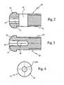
- each of the screw means 30 is formed by a pin having a threaded portion 33 on the outer surface thereof and, at the opposite end, a head portion 36 having a greater diameter with respect to the rest to allow it to abut against the outer surface of the lower plate 20.
- each pin Inside each pin an axial duct 31 is formed, which terminates in the head portion 36 with an outlet 32 open towards the outside to allow water delivery by the screw/nozzle 30.
- connection in fluid communication between the axial duct 31 and the distribution chamber 50 of the spray device is ensured by a transverse duct 34.
- a portion of the axial delivery duct 31 has a polygonal section in proximity to the outlet 32 to allow clamping or loosening of the pin by means of a tool.
- the axial hole can have a hexagonal section to allow the use of a common "Allen” wrench (or hexagonal key), but other configurations can also be provided according to the tool to be used.
- the pins can be made of plastic materials with high tensile strength, such as GRILAMID® TR55, or of metal materials such as steel or the like.
- the pins having the function of screw/nozzle can also be transparent, for example to allow the passage of light which is projected from one or more sources towards the space in which water is delivered from the spray device.
- the screw means 30 are inserted in the through holes 23 of the lower plate 20.
- the elastic sealing ring 5 is then positioned on the plate 20 using as reference, or as support, the pins projecting from the screw means 30 to obtain correct positioning of the sealing ring.
- the assembly is then completed by positioning the upper plate 10, on which a supply coupling (not shown) has previously been mounted, to coincide with the hole 11, above the sealing ring 5 and screwing the screw means 30 into the threaded holes 13 preferably exerting the same tightening torque on each screw/nozzle 30, and if necessary tightening or loosening the screw if anomalies in water distribution to the nozzles or problems of peripheral seal of the spray device should occur.
- the peripheral portions of the spray device appear schematically as those shown in Figure 5 , which also shows the nozzles 40 and the distribution chamber 50 delimited by the plates 10, 20 and by the sealing ring 5.
- the nozzles 40 can be of the type normally used in these products, for example nozzles made of elastomeric material and pressure-inserted in the holes 21, or maintained in position by appropriate locking means, such as elastic washers or the like.
- the screws/nozzles 30 are positioned along a closed perimeter line which surrounds all the delivery nozzles 40, therefore coinciding with the lines along which the holes 13 and 23 are positioned on the respective plates 10 and 20.
- the head portions 36 of the screws/nozzles 30 have a shape substantially similar to that of the nozzles 40, so as to be substantially imperceptible, except after careful observation, to avoid compromising the appearance of the spray device as a whole.
- the head portions 36 could also have a significantly different shape and/or colour to the nozzles 40.
- the head portion 36 could be made with a hexagonal or quadrangular shape to allow loosening or clamping using a common adjustable wrench of standard size.
- the shape of the spray device can be differ from circular, for example quadrangular or other more or less regular fancy shapes.
- the holes formed in the upper plate 10 can also be smooth holes, and in this case clamping nuts should be provided for the screws 30.
- the hexagonal hole of the duct 31 and of the outlet 32 can be positioned axially also in the threaded portion of the screw/nozzle 30.
- other systems can also be provided to allow clamping or loosening, such as slots for screwdrivers positioned at one of the two ends, or polygonal shapes even produced in an extension of the threaded portion.
Landscapes
- Nozzles (AREA)
- Massaging Devices (AREA)
- Catching Or Destruction (AREA)
Claims (6)
- Duschkopf umfassend wenigstens eine untere Platte (20), in welcher eine Vielzahl von Wasserabgabedüsen (40) angeordnet sind, wenigstens eine obere Platte (10), in welcher wenigstens ein Einlass (11) für die Wasserzufuhr geformt ist, wenigstens ein zwischen den beiden Platten (10, 20) angeordnetes elastisches Dichtungselement (5), um dadurch einen Raum (50) zur Verteilung von Wasser zu den Düsen (40) abzugrenzen, und Schraubmittel (30) zum Klemmen des elastischen Dichtungselements (5) zwischen die beiden Platten (10, 20), dadurch gekennzeichnet, dass die Schraubmittel (30) eine Vielzahl von Gewindestangen mit wenigstens einem axialen Kanal (31) mit einer nach außen gerichteten Öffnung (32) umfassen, um die Wasserzufuhr zu ermöglichen und wenigstens einen Querkanal (34), um den Verteilungsraum (50) in Flüssigkeitsverbindung mit dem axialen Kanal (31) zur Wasserzufuhr zu verbinden.
- Duschkopf gemäß Anspruch 1, wobei die Stangen in einem Bereich (33) auf deren äußeren Oberfläche mit einem Gewinde versehen sind und in Löcher (13) mit Innengewinde in der oberen Platte (10) eingreifen.
- Duschkopf gemäß Anspruch 1, wobei die Stangen in Durchtrittsöffnungen (23) in der unteren Platte (20) eingesetzt sind und mit einem Kopfteil (36) versehen sind, um sich gegen die äußere Oberfläche der unteren Platte (20) abzustützen.
- Duschkopf gemäß Anspruch 1, wobei die Stangen entlang einer geschlossenen Umfangslinie angeordnet sind, welche die Verteilungsdüsen (40) umrandet.
- Duschkopf gemäß Anspruch 1, wobei der axiale Kanal (31) der Stangen einen Bereich mit mehreckigem Querschnitt in der Nähe der Öffnung (32) hat, um ein Klemmen oder Lösen der Stange mittels eines Werkzeugs zu ermöglichen.
- Duschkopf gemäß Anspruch 1, wobei das elastische Dichtungselement (5) durch einen geschlossenen Ring ausgebildet ist.
Applications Claiming Priority (1)
| Application Number | Priority Date | Filing Date | Title |
|---|---|---|---|
| IT000338A ITMI20080338A1 (it) | 2008-02-29 | 2008-02-29 | Diffusore per doccia e relativi ugelli di erogazione |
Publications (3)
| Publication Number | Publication Date |
|---|---|
| EP2095878A1 EP2095878A1 (de) | 2009-09-02 |
| EP2095878A8 EP2095878A8 (de) | 2009-10-28 |
| EP2095878B1 true EP2095878B1 (de) | 2011-01-12 |
Family
ID=40291728
Family Applications (1)
| Application Number | Title | Priority Date | Filing Date |
|---|---|---|---|
| EP09001638A Active EP2095878B1 (de) | 2008-02-29 | 2009-02-05 | Duschkopf und zugehörige Düsen |
Country Status (5)
| Country | Link |
|---|---|
| US (1) | US8109451B2 (de) |
| EP (1) | EP2095878B1 (de) |
| AT (1) | ATE494958T1 (de) |
| DE (1) | DE602009000545D1 (de) |
| IT (1) | ITMI20080338A1 (de) |
Cited By (2)
| Publication number | Priority date | Publication date | Assignee | Title |
|---|---|---|---|---|
| US8109451B2 (en) | 2008-02-29 | 2012-02-07 | Ergon S.R.L. | Shower spray device and related delivery nozzles |
| USD694366S1 (en) | 2011-01-14 | 2013-11-26 | Kohler Co. | Faucet |
Families Citing this family (35)
| Publication number | Priority date | Publication date | Assignee | Title |
|---|---|---|---|---|
| US7114666B2 (en) | 2002-12-10 | 2006-10-03 | Water Pik, Inc. | Dual massage shower head |
| US7740186B2 (en) | 2004-09-01 | 2010-06-22 | Water Pik, Inc. | Drenching shower head |
| US7789326B2 (en) | 2006-12-29 | 2010-09-07 | Water Pik, Inc. | Handheld showerhead with mode control and method of selecting a handheld showerhead mode |
| US8020787B2 (en) | 2006-11-29 | 2011-09-20 | Water Pik, Inc. | Showerhead system |
| US8794543B2 (en) | 2006-12-28 | 2014-08-05 | Water Pik, Inc. | Low-speed pulsating showerhead |
| US8366024B2 (en) | 2006-12-28 | 2013-02-05 | Water Pik, Inc. | Low speed pulsating showerhead |
| US8371618B2 (en) | 2007-05-04 | 2013-02-12 | Water Pik, Inc. | Hidden pivot attachment for showers and method of making same |
| PT2310136E (pt) * | 2008-07-15 | 2013-02-13 | Crs Spa | Cabeça de chuveiro com bocais amovíveis, conjunto de cabeça de chuveiro e processo de manutenção para cabeça de chuveiro |
| CA2678769C (en) | 2008-09-15 | 2014-07-29 | Water Pik, Inc. | Shower assembly with radial mode changer |
| USD625776S1 (en) | 2009-10-05 | 2010-10-19 | Water Pik, Inc. | Showerhead |
| US8616470B2 (en) | 2010-08-25 | 2013-12-31 | Water Pik, Inc. | Mode control valve in showerhead connector |
| CN102296322B (zh) * | 2011-06-15 | 2014-01-29 | 天津大学 | 一种电化学合成五氧化二氮用的隔膜及其制备方法 |
| USD678467S1 (en) | 2012-01-27 | 2013-03-19 | Water Pik, Inc. | Ring-shaped handheld showerhead |
| USD678463S1 (en) | 2012-01-27 | 2013-03-19 | Water Pik, Inc. | Ring-shaped wall mount showerhead |
| USD694357S1 (en) | 2012-03-09 | 2013-11-26 | Durst Corporation, Inc. | Showerhead |
| CA2976867C (en) | 2012-06-22 | 2021-03-02 | Water Pik, Inc. | Bracket for showerhead with integral flow control |
| US20140287632A1 (en) * | 2013-03-22 | 2014-09-25 | Jeremy Brown | Screw with hole and method |
| US9404243B2 (en) | 2013-06-13 | 2016-08-02 | Water Pik, Inc. | Showerhead with turbine driven shutter |
| USD744066S1 (en) | 2014-06-13 | 2015-11-24 | Water Pik, Inc. | Wall mount showerhead |
| USD744612S1 (en) | 2014-06-13 | 2015-12-01 | Water Pik, Inc. | Handheld showerhead |
| USD744065S1 (en) | 2014-06-13 | 2015-11-24 | Water Pik, Inc. | Handheld showerhead |
| USD744614S1 (en) | 2014-06-13 | 2015-12-01 | Water Pik, Inc. | Wall mount showerhead |
| USD744064S1 (en) | 2014-06-13 | 2015-11-24 | Water Pik, Inc. | Handheld showerhead |
| USD745111S1 (en) | 2014-06-13 | 2015-12-08 | Water Pik, Inc. | Wall mount showerhead |
| USD744611S1 (en) | 2014-06-13 | 2015-12-01 | Water Pik, Inc. | Handheld showerhead |
| US10413917B2 (en) * | 2014-09-03 | 2019-09-17 | Kohler Co. | Shower |
| WO2016203349A1 (en) * | 2015-06-18 | 2016-12-22 | Calflex S.R.L. | Shower head |
| USD803981S1 (en) | 2016-02-01 | 2017-11-28 | Water Pik, Inc. | Handheld spray nozzle |
| CN108883426B (zh) | 2016-02-01 | 2021-04-27 | 洁碧有限公司 | 手持式宠物用喷射棒 |
| US10265710B2 (en) | 2016-04-15 | 2019-04-23 | Water Pik, Inc. | Showerhead with dual oscillating massage |
| USD970684S1 (en) | 2016-04-15 | 2022-11-22 | Water Pik, Inc. | Showerhead |
| WO2018049213A1 (en) | 2016-09-08 | 2018-03-15 | Water Pik, Inc. | Pause assembly for showerheads |
| USD843549S1 (en) | 2017-07-19 | 2019-03-19 | Water Pik, Inc. | Handheld spray nozzle |
| USD872227S1 (en) | 2018-04-20 | 2020-01-07 | Water Pik, Inc. | Handheld spray device |
| DE102019200012A1 (de) * | 2019-01-02 | 2020-07-02 | Hansgrohe Se | Brausekopf mit Strahlscheibenhaltevorrichtung |
Family Cites Families (10)
| Publication number | Priority date | Publication date | Assignee | Title |
|---|---|---|---|---|
| US4221336A (en) * | 1978-10-31 | 1980-09-09 | Diamond Harvey E | Nozzle with directionally variable outlet |
| US4379097A (en) * | 1981-04-03 | 1983-04-05 | Leggett Wilbur P | Hydrotherapy jet unit |
| DE3834092A1 (de) * | 1988-10-07 | 1990-04-12 | Progress Werk Oberkirch Ag | Gasbrenner, insbesondere verdampfungsoelbrenner mit einer brennerduese |
| DE4230678A1 (de) * | 1992-09-14 | 1994-03-17 | Krummenauer Gmbh & Co Kg | Meißelhalter für eine Schrämwalze oder einen Schneidkopf |
| US6250572B1 (en) * | 2000-09-07 | 2001-06-26 | Globe Union Industrial Corp. | Showerhead |
| ATE353250T1 (de) * | 2002-12-12 | 2007-02-15 | Hansgrohe Ag | Brause mit luftzuführung |
| ITMI20041756A1 (it) * | 2004-09-15 | 2004-12-15 | Ergon S R L | Dispositivo diffusore per doccia |
| TWM293005U (en) | 2006-02-27 | 2006-07-01 | Wu-Ting Hsiao | Improved structure of patterned shower head |
| ATE442909T1 (de) | 2006-03-31 | 2009-10-15 | Crs Spa | Brausekopf |
| ITMI20080338A1 (it) | 2008-02-29 | 2009-09-01 | Ergon Srl | Diffusore per doccia e relativi ugelli di erogazione |
-
2008
- 2008-02-29 IT IT000338A patent/ITMI20080338A1/it unknown
-
2009
- 2009-02-05 EP EP09001638A patent/EP2095878B1/de active Active
- 2009-02-05 AT AT09001638T patent/ATE494958T1/de not_active IP Right Cessation
- 2009-02-05 DE DE602009000545T patent/DE602009000545D1/de active Active
- 2009-02-09 US US12/367,696 patent/US8109451B2/en active Active
Cited By (7)
| Publication number | Priority date | Publication date | Assignee | Title |
|---|---|---|---|---|
| US8109451B2 (en) | 2008-02-29 | 2012-02-07 | Ergon S.R.L. | Shower spray device and related delivery nozzles |
| USD694366S1 (en) | 2011-01-14 | 2013-11-26 | Kohler Co. | Faucet |
| USD698420S1 (en) | 2011-01-14 | 2014-01-28 | Kohler Co. | Faucet |
| USD704805S1 (en) | 2011-01-14 | 2014-05-13 | Kohler Co. | Faucet handle |
| USD704807S1 (en) | 2011-01-14 | 2014-05-13 | Kohler Co. | Waterspout |
| USD704802S1 (en) | 2011-01-14 | 2014-05-13 | Kohler Co. | Faucet |
| USD704800S1 (en) | 2011-01-14 | 2014-05-13 | Kohler Co. | Showerhead |
Also Published As
| Publication number | Publication date |
|---|---|
| US8109451B2 (en) | 2012-02-07 |
| ATE494958T1 (de) | 2011-01-15 |
| ITMI20080338A1 (it) | 2009-09-01 |
| US20090218420A1 (en) | 2009-09-03 |
| EP2095878A8 (de) | 2009-10-28 |
| DE602009000545D1 (de) | 2011-02-24 |
| EP2095878A1 (de) | 2009-09-02 |
Similar Documents
| Publication | Publication Date | Title |
|---|---|---|
| US8109451B2 (en) | Shower spray device and related delivery nozzles | |
| US11975350B2 (en) | Adhesive dispensing system with convertible nozzle assemblies | |
| EP1637231B1 (de) | Brausekopf | |
| US11543038B2 (en) | Dense phase pump with easily replaceable components | |
| KR101899029B1 (ko) | 다중-분무 비데 | |
| ES2503417T3 (es) | Sistema dispensador universal para extrusión asistida por aire de filamentos de líquido | |
| USRE41302E1 (en) | Sprinkler diffuser device, especially for plants for the spray distribution of water and other similar liquids | |
| US7543856B2 (en) | Tubing connecting device | |
| WO1999049980A1 (en) | Control valve arrangement for spraying systems | |
| US20100294856A1 (en) | Connection of a spray head to a robot arm | |
| US7434751B1 (en) | Water spraying gun having different spraying types | |
| ES2661828T3 (es) | Dispositivo para suministrar a un pulverizador un producto de revestimiento líquido | |
| US6827299B2 (en) | Gang mountable spray gun | |
| MY147693A (en) | Liquid discharge apparatus | |
| EP2453153B1 (de) | Vorrichtung zur Flüssigkeitsförderung und/oder -Verteilung mit Ringmutterkupplung | |
| CN105705251A (zh) | 用于将液体涂覆产品供给喷涂器的装置以及安装/拆卸该装置的工具 | |
| US20080119073A1 (en) | Electric plug connector for wall fastening | |
| JP2021506290A (ja) | 散布アセンブリ、及び農業植物保護機 | |
| WO2010105891A3 (en) | Burner assembly | |
| CN114423945B (zh) | 单轴偏心螺杆泵 | |
| JP5551010B2 (ja) | 散気システム | |
| CA2845434C (en) | Orifice selector module for liquid fertilizer distribution systems | |
| CN219309136U (zh) | 喷嘴结构 | |
| CN216078719U (zh) | 一种管连接结构及喷水枪 | |
| CN210658546U (zh) | 一种带扳手功能的花洒固定装置 |
Legal Events
| Date | Code | Title | Description |
|---|---|---|---|
| PUAI | Public reference made under article 153(3) epc to a published international application that has entered the european phase |
Free format text: ORIGINAL CODE: 0009012 |
|
| AK | Designated contracting states |
Kind code of ref document: A1 Designated state(s): AT BE BG CH CY CZ DE DK EE ES FI FR GB GR HR HU IE IS IT LI LT LU LV MC MK MT NL NO PL PT RO SE SI SK TR |
|
| AX | Request for extension of the european patent |
Extension state: AL BA RS |
|
| RTI1 | Title (correction) |
Free format text: SHOWER HEAD AND NOZZLES FOR THE SAME |
|
| 17P | Request for examination filed |
Effective date: 20100224 |
|
| AKX | Designation fees paid |
Designated state(s): AT BE BG CH CY CZ DE DK EE ES FI FR GB GR HR HU IE IS IT LI LT LU LV MC MK MT NL NO PL PT RO SE SI SK TR |
|
| GRAP | Despatch of communication of intention to grant a patent |
Free format text: ORIGINAL CODE: EPIDOSNIGR1 |
|
| GRAS | Grant fee paid |
Free format text: ORIGINAL CODE: EPIDOSNIGR3 |
|
| GRAA | (expected) grant |
Free format text: ORIGINAL CODE: 0009210 |
|
| AK | Designated contracting states |
Kind code of ref document: B1 Designated state(s): AT BE BG CH CY CZ DE DK EE ES FI FR GB GR HR HU IE IS IT LI LT LU LV MC MK MT NL NO PL PT RO SE SI SK TR |
|
| REG | Reference to a national code |
Ref country code: GB Ref legal event code: FG4D |
|
| REG | Reference to a national code |
Ref country code: CH Ref legal event code: EP |
|
| REG | Reference to a national code |
Ref country code: CH Ref legal event code: NV Representative=s name: KAMINSKI HARMANN PATENTANWAELTE EST. |
|
| REG | Reference to a national code |
Ref country code: IE Ref legal event code: FG4D |
|
| REF | Corresponds to: |
Ref document number: 602009000545 Country of ref document: DE Date of ref document: 20110224 Kind code of ref document: P |
|
| REG | Reference to a national code |
Ref country code: DE Ref legal event code: R096 Ref document number: 602009000545 Country of ref document: DE Effective date: 20110224 |
|
| REG | Reference to a national code |
Ref country code: NL Ref legal event code: VDEP Effective date: 20110112 |
|
| LTIE | Lt: invalidation of european patent or patent extension |
Effective date: 20110112 |
|
| PG25 | Lapsed in a contracting state [announced via postgrant information from national office to epo] |
Ref country code: GR Free format text: LAPSE BECAUSE OF FAILURE TO SUBMIT A TRANSLATION OF THE DESCRIPTION OR TO PAY THE FEE WITHIN THE PRESCRIBED TIME-LIMIT Effective date: 20110413 Ref country code: LV Free format text: LAPSE BECAUSE OF FAILURE TO SUBMIT A TRANSLATION OF THE DESCRIPTION OR TO PAY THE FEE WITHIN THE PRESCRIBED TIME-LIMIT Effective date: 20110112 Ref country code: LT Free format text: LAPSE BECAUSE OF FAILURE TO SUBMIT A TRANSLATION OF THE DESCRIPTION OR TO PAY THE FEE WITHIN THE PRESCRIBED TIME-LIMIT Effective date: 20110112 Ref country code: IS Free format text: LAPSE BECAUSE OF FAILURE TO SUBMIT A TRANSLATION OF THE DESCRIPTION OR TO PAY THE FEE WITHIN THE PRESCRIBED TIME-LIMIT Effective date: 20110512 Ref country code: SE Free format text: LAPSE BECAUSE OF FAILURE TO SUBMIT A TRANSLATION OF THE DESCRIPTION OR TO PAY THE FEE WITHIN THE PRESCRIBED TIME-LIMIT Effective date: 20110112 Ref country code: PT Free format text: LAPSE BECAUSE OF FAILURE TO SUBMIT A TRANSLATION OF THE DESCRIPTION OR TO PAY THE FEE WITHIN THE PRESCRIBED TIME-LIMIT Effective date: 20110512 Ref country code: NO Free format text: LAPSE BECAUSE OF FAILURE TO SUBMIT A TRANSLATION OF THE DESCRIPTION OR TO PAY THE FEE WITHIN THE PRESCRIBED TIME-LIMIT Effective date: 20110412 Ref country code: ES Free format text: LAPSE BECAUSE OF FAILURE TO SUBMIT A TRANSLATION OF THE DESCRIPTION OR TO PAY THE FEE WITHIN THE PRESCRIBED TIME-LIMIT Effective date: 20110423 Ref country code: HR Free format text: LAPSE BECAUSE OF FAILURE TO SUBMIT A TRANSLATION OF THE DESCRIPTION OR TO PAY THE FEE WITHIN THE PRESCRIBED TIME-LIMIT Effective date: 20110112 |
|
| PG25 | Lapsed in a contracting state [announced via postgrant information from national office to epo] |
Ref country code: FI Free format text: LAPSE BECAUSE OF FAILURE TO SUBMIT A TRANSLATION OF THE DESCRIPTION OR TO PAY THE FEE WITHIN THE PRESCRIBED TIME-LIMIT Effective date: 20110112 Ref country code: AT Free format text: LAPSE BECAUSE OF FAILURE TO SUBMIT A TRANSLATION OF THE DESCRIPTION OR TO PAY THE FEE WITHIN THE PRESCRIBED TIME-LIMIT Effective date: 20110112 Ref country code: BG Free format text: LAPSE BECAUSE OF FAILURE TO SUBMIT A TRANSLATION OF THE DESCRIPTION OR TO PAY THE FEE WITHIN THE PRESCRIBED TIME-LIMIT Effective date: 20110412 Ref country code: NL Free format text: LAPSE BECAUSE OF FAILURE TO SUBMIT A TRANSLATION OF THE DESCRIPTION OR TO PAY THE FEE WITHIN THE PRESCRIBED TIME-LIMIT Effective date: 20110112 Ref country code: SI Free format text: LAPSE BECAUSE OF FAILURE TO SUBMIT A TRANSLATION OF THE DESCRIPTION OR TO PAY THE FEE WITHIN THE PRESCRIBED TIME-LIMIT Effective date: 20110112 Ref country code: CY Free format text: LAPSE BECAUSE OF FAILURE TO SUBMIT A TRANSLATION OF THE DESCRIPTION OR TO PAY THE FEE WITHIN THE PRESCRIBED TIME-LIMIT Effective date: 20110112 Ref country code: BE Free format text: LAPSE BECAUSE OF FAILURE TO SUBMIT A TRANSLATION OF THE DESCRIPTION OR TO PAY THE FEE WITHIN THE PRESCRIBED TIME-LIMIT Effective date: 20110112 Ref country code: PL Free format text: LAPSE BECAUSE OF FAILURE TO SUBMIT A TRANSLATION OF THE DESCRIPTION OR TO PAY THE FEE WITHIN THE PRESCRIBED TIME-LIMIT Effective date: 20110112 |
|
| PG25 | Lapsed in a contracting state [announced via postgrant information from national office to epo] |
Ref country code: MC Free format text: LAPSE BECAUSE OF NON-PAYMENT OF DUE FEES Effective date: 20110228 |
|
| PG25 | Lapsed in a contracting state [announced via postgrant information from national office to epo] |
Ref country code: EE Free format text: LAPSE BECAUSE OF FAILURE TO SUBMIT A TRANSLATION OF THE DESCRIPTION OR TO PAY THE FEE WITHIN THE PRESCRIBED TIME-LIMIT Effective date: 20110112 Ref country code: DK Free format text: LAPSE BECAUSE OF FAILURE TO SUBMIT A TRANSLATION OF THE DESCRIPTION OR TO PAY THE FEE WITHIN THE PRESCRIBED TIME-LIMIT Effective date: 20110112 |
|
| PLBE | No opposition filed within time limit |
Free format text: ORIGINAL CODE: 0009261 |
|
| STAA | Information on the status of an ep patent application or granted ep patent |
Free format text: STATUS: NO OPPOSITION FILED WITHIN TIME LIMIT |
|
| REG | Reference to a national code |
Ref country code: IE Ref legal event code: MM4A |
|
| PG25 | Lapsed in a contracting state [announced via postgrant information from national office to epo] |
Ref country code: CZ Free format text: LAPSE BECAUSE OF FAILURE TO SUBMIT A TRANSLATION OF THE DESCRIPTION OR TO PAY THE FEE WITHIN THE PRESCRIBED TIME-LIMIT Effective date: 20110112 Ref country code: SK Free format text: LAPSE BECAUSE OF FAILURE TO SUBMIT A TRANSLATION OF THE DESCRIPTION OR TO PAY THE FEE WITHIN THE PRESCRIBED TIME-LIMIT Effective date: 20110112 Ref country code: RO Free format text: LAPSE BECAUSE OF FAILURE TO SUBMIT A TRANSLATION OF THE DESCRIPTION OR TO PAY THE FEE WITHIN THE PRESCRIBED TIME-LIMIT Effective date: 20110112 |
|
| 26N | No opposition filed |
Effective date: 20111013 |
|
| PG25 | Lapsed in a contracting state [announced via postgrant information from national office to epo] |
Ref country code: MT Free format text: LAPSE BECAUSE OF FAILURE TO SUBMIT A TRANSLATION OF THE DESCRIPTION OR TO PAY THE FEE WITHIN THE PRESCRIBED TIME-LIMIT Effective date: 20110112 |
|
| PG25 | Lapsed in a contracting state [announced via postgrant information from national office to epo] |
Ref country code: IE Free format text: LAPSE BECAUSE OF NON-PAYMENT OF DUE FEES Effective date: 20110205 |
|
| REG | Reference to a national code |
Ref country code: DE Ref legal event code: R097 Ref document number: 602009000545 Country of ref document: DE Effective date: 20111013 |
|
| PG25 | Lapsed in a contracting state [announced via postgrant information from national office to epo] |
Ref country code: MK Free format text: LAPSE BECAUSE OF FAILURE TO SUBMIT A TRANSLATION OF THE DESCRIPTION OR TO PAY THE FEE WITHIN THE PRESCRIBED TIME-LIMIT Effective date: 20110112 |
|
| PG25 | Lapsed in a contracting state [announced via postgrant information from national office to epo] |
Ref country code: LU Free format text: LAPSE BECAUSE OF NON-PAYMENT OF DUE FEES Effective date: 20110205 |
|
| PG25 | Lapsed in a contracting state [announced via postgrant information from national office to epo] |
Ref country code: TR Free format text: LAPSE BECAUSE OF FAILURE TO SUBMIT A TRANSLATION OF THE DESCRIPTION OR TO PAY THE FEE WITHIN THE PRESCRIBED TIME-LIMIT Effective date: 20110112 |
|
| PG25 | Lapsed in a contracting state [announced via postgrant information from national office to epo] |
Ref country code: HU Free format text: LAPSE BECAUSE OF FAILURE TO SUBMIT A TRANSLATION OF THE DESCRIPTION OR TO PAY THE FEE WITHIN THE PRESCRIBED TIME-LIMIT Effective date: 20110112 |
|
| REG | Reference to a national code |
Ref country code: DE Ref legal event code: R082 Ref document number: 602009000545 Country of ref document: DE Representative=s name: GODEMEYER BLUM LENZE PARTNERSCHAFT, PATENTANWA, DE Ref country code: DE Ref legal event code: R082 Ref document number: 602009000545 Country of ref document: DE Representative=s name: GODEMEYER BLUM LENZE PATENTANWAELTE, PARTNERSC, DE Ref country code: DE Ref legal event code: R082 Ref document number: 602009000545 Country of ref document: DE Representative=s name: GODEMEYER BLUM LENZE - WERKPATENT, DE |
|
| REG | Reference to a national code |
Ref country code: FR Ref legal event code: PLFP Year of fee payment: 7 |
|
| REG | Reference to a national code |
Ref country code: FR Ref legal event code: PLFP Year of fee payment: 8 |
|
| REG | Reference to a national code |
Ref country code: FR Ref legal event code: PLFP Year of fee payment: 9 |
|
| REG | Reference to a national code |
Ref country code: CH Ref legal event code: NV Representative=s name: FABIANO, FRANKE AND MGT SAGL, CH |
|
| REG | Reference to a national code |
Ref country code: FR Ref legal event code: PLFP Year of fee payment: 10 |
|
| REG | Reference to a national code |
Ref country code: CH Ref legal event code: PCAR Free format text: NEW ADDRESS: PIAZZETTA SAN CARLO 2, 6900 LUGANO (CH) |
|
| REG | Reference to a national code |
Ref country code: CH Ref legal event code: U11 Free format text: ST27 STATUS EVENT CODE: U-0-0-U10-U11 (AS PROVIDED BY THE NATIONAL OFFICE) Effective date: 20260301 |
|
| PGFP | Annual fee paid to national office [announced via postgrant information from national office to epo] |
Ref country code: GB Payment date: 20260218 Year of fee payment: 18 |
|
| PGFP | Annual fee paid to national office [announced via postgrant information from national office to epo] |
Ref country code: DE Payment date: 20260217 Year of fee payment: 18 |
|
| PGFP | Annual fee paid to national office [announced via postgrant information from national office to epo] |
Ref country code: IT Payment date: 20260217 Year of fee payment: 18 |
|
| PGFP | Annual fee paid to national office [announced via postgrant information from national office to epo] |
Ref country code: FR Payment date: 20260218 Year of fee payment: 18 |
|
| PGFP | Annual fee paid to national office [announced via postgrant information from national office to epo] |
Ref country code: CH Payment date: 20260301 Year of fee payment: 18 |