EP2095902A1 - Appareil de soudage à l'arc - Google Patents
Appareil de soudage à l'arc Download PDFInfo
- Publication number
- EP2095902A1 EP2095902A1 EP09001500A EP09001500A EP2095902A1 EP 2095902 A1 EP2095902 A1 EP 2095902A1 EP 09001500 A EP09001500 A EP 09001500A EP 09001500 A EP09001500 A EP 09001500A EP 2095902 A1 EP2095902 A1 EP 2095902A1
- Authority
- EP
- European Patent Office
- Prior art keywords
- welding
- control
- power source
- arc
- feed
- Prior art date
- Legal status (The legal status is an assumption and is not a legal conclusion. Google has not performed a legal analysis and makes no representation as to the accuracy of the status listed.)
- Withdrawn
Links
Images
Classifications
-
- B—PERFORMING OPERATIONS; TRANSPORTING
- B23—MACHINE TOOLS; METAL-WORKING NOT OTHERWISE PROVIDED FOR
- B23K—SOLDERING OR UNSOLDERING; WELDING; CLADDING OR PLATING BY SOLDERING OR WELDING; CUTTING BY APPLYING HEAT LOCALLY, e.g. FLAME CUTTING; WORKING BY LASER BEAM
- B23K9/00—Arc welding or cutting
- B23K9/10—Other electric circuits therefor; Protective circuits; Remote controls
- B23K9/1006—Power supply
-
- B—PERFORMING OPERATIONS; TRANSPORTING
- B23—MACHINE TOOLS; METAL-WORKING NOT OTHERWISE PROVIDED FOR
- B23K—SOLDERING OR UNSOLDERING; WELDING; CLADDING OR PLATING BY SOLDERING OR WELDING; CUTTING BY APPLYING HEAT LOCALLY, e.g. FLAME CUTTING; WORKING BY LASER BEAM
- B23K9/00—Arc welding or cutting
- B23K9/10—Other electric circuits therefor; Protective circuits; Remote controls
- B23K9/1093—Consumable electrode or filler wire preheat circuits
-
- B—PERFORMING OPERATIONS; TRANSPORTING
- B23—MACHINE TOOLS; METAL-WORKING NOT OTHERWISE PROVIDED FOR
- B23K—SOLDERING OR UNSOLDERING; WELDING; CLADDING OR PLATING BY SOLDERING OR WELDING; CUTTING BY APPLYING HEAT LOCALLY, e.g. FLAME CUTTING; WORKING BY LASER BEAM
- B23K9/00—Arc welding or cutting
- B23K9/12—Automatic feeding or moving of electrodes or work for spot or seam welding or cutting
- B23K9/133—Means for feeding electrodes, e.g. drums, rolls, motors
-
- B—PERFORMING OPERATIONS; TRANSPORTING
- B23—MACHINE TOOLS; METAL-WORKING NOT OTHERWISE PROVIDED FOR
- B23K—SOLDERING OR UNSOLDERING; WELDING; CLADDING OR PLATING BY SOLDERING OR WELDING; CUTTING BY APPLYING HEAT LOCALLY, e.g. FLAME CUTTING; WORKING BY LASER BEAM
- B23K9/00—Arc welding or cutting
- B23K9/16—Arc welding or cutting making use of shielding gas
- B23K9/167—Arc welding or cutting making use of shielding gas and of a non-consumable electrode
Definitions
- the invention relates to an arc welding apparatus comprising a welding power source, by means of which an arc between a non-consumable electrode and a workpiece can be generated, in particular for TIG and / or plasma welding, and further comprising a feed part for the defined feeding of welding filler material to the workpiece, wherein the feed part a Feed control is assigned to control the feed part.
- an arc can be generated between a non-consumable electrode and a workpiece to be welded.
- the arc acting on the workpiece creates a weld pool for welding the workpiece.
- a filler metal such as a rod electrode or a welding wire, may be supplied to the molten bath.
- the feed takes place by means of a feed part.
- the feed part is controlled by a feed control, so that the filler metal can be supplied automatically depending on the course of the welding process, in particular as a function of the welding speed and / or the quality of the arc.
- the welding power source provides the required electrical energy for the welding process and is usually designed in the form of a manageable unit.
- the feed control forms a second unit in combination with the feed part.
- the two components can be matched.
- connection cable between the welding power source and the feed control can impair the functional reliability of the arc welder. For example, there is a risk of the welder stumbling over the connection cable and breaking the electrical connection.
- adjustment or adjustment of the welding power source and the feed control requires a not inconsiderable amount of time and is a source of danger if the adjustment is not performed carefully by the welder.
- Object of the present invention is to develop an arc welding device of the type mentioned in such a way that it has a simpler handling and improved reliability.
- the welding power source together with the feed part and / or the feed control form a common functional unit. This is easy to handle by the user, since the said components are held on a common support member.
- Such a configuration is particularly suitable for mobile use of the arc welding machine.
- the welding power source and the feed control may be connected to each other at the manufacturer side via a fixed wiring, so that the welder does not need to connect any additional electrical connection cables to connect the electric components of the arc welder with each other.
- An electrical adjustment of the components by the welder can be omitted. Required adjustments can be made by the manufacturer.
- the number of components of the arc welding device which must be manually matched by the user and / or connected to each other, can be significantly reduced.
- the risk of incorrect operation is thereby reduced and thus the reliability is increased.
- the handling of the arc welder simplifies.
- the arc welding device according to the invention can be configured in particular as a TIG welding device (tungsten inert gas, in the English-speaking world tungsten inert gas (TIG)) or in the form of a plasma welding device.
- TIG welding device tungsten inert gas, in the English-speaking world tungsten inert gas (TIG)
- TIG tungsten inert gas
- the welding power source forms together with the feed part and the feed control a common functional unit which is held on or in a support member, wherein conveniently also the supply of welding filler material is arranged on or in the support member.
- the support member forms in an advantageous embodiment of the invention, the housing of the arc welding machine.
- the housing forms a mechanical support both the welding power source and the feed part and / or the feed control.
- the supply of welding filler material is integrated into the housing of the arc welding device or outside of the housing.
- a further simplification of the handling of the arc welding device according to the invention is achieved in a preferred embodiment in that the welding power source and the feed control are jointly assigned to a display and control panel.
- the latter is preferably held on or in the common support member.
- the user can set and read welding process parameters on the display and control panel, with the display and control panel associated with both the welding power source and the feed control.
- the arc welder is designed very clear and can be operated by the user in a simple way.
- the arc welding device has a central control device, which is held on or in the common support member and electrically connected to the welding power source and the feed control.
- the central control device controls the welding process, wherein, for example, the quality of the arc between the non-consumable electrode and the workpiece and also the advancing movement of the welding consumable material can be predetermined by the central control device.
- This is as well as the welding power source and the feed control held on or in the central support member, in particular can be provided be that the central control device is integrated into the housing of the arc welder.
- the arc welding device has a positioning control held on or in the common support part for controlling a workpiece positioning device and / or a welding head positioning device.
- the workpiece positioning device By means of the workpiece positioning device, the workpiece can be moved relative to the non-consumable electrode during the welding process.
- the corresponding control signals are received by the workpiece positioning device from the positioning control of the arc welding device.
- the workpiece positioning device can be designed, for example, in the form of a turntable on which the workpiece to be welded can be positioned and which can be rotated during the welding process.
- a welding head of the arc welding device can be moved relative to the workpiece during the welding process.
- the welding head may comprise a welding torch and / or a positioning unit for positioning the welding filler material on the workpiece. Due to the arrangement of the positioning control on or in the common support part of the arc welding device and the positioning control forms a device component, which forms a single manageable unit together with the welding power source and the feed part and / or the feed control.
- a welding wire is used as the welding filler material and the arc welding device has a controllable heating current source held on or in the common supporting part for heating the free end of the welding wire facing the workpiece.
- the arc supplied to the welding wire is heated by the arc.
- the arc is deprived of energy and thus the welding process is influenced.
- it is advantageous if the free end of the welding wire before it is fed to the arc for example Resistance heating is heated.
- the free end of the welding wire is in this case heated to a high temperature, but without forming an arc between the welding wire and the workpiece and without the welding wire already melts.
- the heating current source has only a low working voltage, so that no arc can form from the free end of the welding wire to the workpiece.
- the Schustrometti forms together with the welding power source, the feed part and / or the feed control and preferably together with the welding wire supply a jointly manageable functional unit, all components on or in the common support member, preferably in a housing of the arc welding device held are. It is thus advantageous if the Schwarzstromario is integrated into the housing of the arc welding machine.
- the common display and control panel which is preferably used are preferably also assigned the central control device, the positioning control and / or the heating current source.
- the central control device, the positioning control and the heating current source each form a device component of the arc welding device.
- These device components can be associated with the common display and control panel, which can be kept as well as the device components mentioned on or in the common support member to form a total of an arc welding device in the form of an easily manageable functional unit.
- the positioning control and / or the heating current source as well as the welding power source and the feed control are electrically connected to the central control device. This makes it possible to easily control the positioning of the workpiece and / or the welding head and the heating of the free end of the welding wire during the welding process by means of the central control device.
- the central control device has at least one central storage element, in which workpiece-specific process parameters of the welding power source, the feed control, the positioning control and / or the Schustromquelle can be stored and retrieved by the user as needed.
- the at least one central memory element gives the possibility of tool-specific process parameters of the welding process save. If a plurality of identical workpieces are to be welded, the optimum welding parameters can be stored in a central storage element during welding of a first workpiece and retrieved by the user for welding further identical workpieces. Thus, for welding processes in which an arc is generated between a non-consumable electrode and a workpiece, a considerable simplification can be achieved.
- technically trained personnel stores the optimum parameters for welding a workpiece in a central storage member and that subsequently, identically designed workpieces are welded by technically less preformed personnel by means of the stored parameters.
- the central control device can form an information processing entity which maintains star-shaped connections to the common display and control panel as well as feed control, the welding power source, the heating current source and the positioning control.
- all these device components can be easily matched and controlled, the device components are integrated together with the central control unit in the housing of the arc welding device and form a single unit.
- the arc welder has a BUS system to which the welding power source, the feed control, the common display and control panel, the central control device, the positioning and / or the Schustromquelle are connected.
- a BUS system for example a CAN bus, facilitates the control of the arc welder and simplifies its construction.
- the common display and control panel has a touch-sensitive screen (touchscreen).
- a gas can be supplied to the non-consumable electrode during the welding process, so that the arc between the non-consumable electrode and the workpiece burns in a special gas atmosphere.
- a protective gas in particular argon, or else a forming gas in the form of a mixture, in particular of nitrogen and hydrogen.
- the supply of the gas during the welding process can be regulated by means of a flow regulator, which is controllable by a gas control device of the arc welding device.
- the gas control device may also be held on or in the common support member.
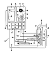
- FIGURE of the drawing shows schematically an arc welding device according to the invention, to which a welding torch and an inert gas reservoir as well as a workpiece and a workpiece positioning device are connected.
- the arc welding device 10 forms a single functional unit, which is designed to be portable in the illustrated embodiment.
- the arc welding device 10 has a housing 12, on the upper side of a carrying handle 14 is fixed.
- the housing 12 forms a supporting part, in which the device components of the arc welding device 10 described in detail below are held.
- a first device component of the arc welding device 10 is a welding power source 16 with a control part 17 and a power section 18.
- a welding power source 16 with a control part 17 and a power section 18.
- a protective gas for example argon
- a gas reservoir 26 can be supplied to the welding torch 22 via a gas line 24.
- a controllable flow regulator 27 is connected in the gas line 24, a controllable flow regulator 27 is connected.
- a second device component which is integrated in the housing 12 of the arc welding device 10 as well as the welding power source 16, is formed by a supply of filler metal, which is configured in the present embodiment as a welding wire 28.
- the welding wire supply 28 may be in the form of a supply drum 29 for welding wire 30.
- the latter can be led out of the housing 12 by means of a feed part 32 and fed to a workpiece 34 to be welded.
- the feed member 32 forms a third device component of the arc welding apparatus 10, which is integrated in the housing 12 and held on this.
- the welding wire supply 28 may also be mounted on the outside of the housing 12, the welding wire 30 being guided through the housing 12 and the advancing part 32.
- An arrangement of the welding wire supply 28 separate from the housing 12 is possible, wherein the welding wire 30 is guided from the supply roll 29 through the housing 12 and the feed member 32 so that it can be supplied from the feed member 32 in a predetermined manner the workpiece 34.
- the feed part 32 is controlled by a feed control 36, which forms a fourth device component of the arc welding device 10 according to the invention and is also integrated in the housing 12.
- the welding power source 16 and the feed control 36 are connected via a bus system 38 to a central control device 40, which forms a further device component of the arc welding device 10 according to the invention and is integrated in the housing 12.
- the BUS system has an interface 39, via which the central control device 40 can be connected to an external control device (not shown in the drawing). This enables external monitoring and logging as well as integration into higher-level automation concepts.
- the interface 39 may be designed in the form of a radio interface or allow the connection of a radio module, so that the arc welding device can be connected via a radio link to an external control device.
- the central control device 40 is connected to a central display and control panel 42 via the BUS system 38. This likewise forms a device component of the arc welding device 10 integrated into the housing 12.
- the workpiece 34 For welding the workpiece 34, this can be connected via a ground line 44 to the power section 18 of the welding power source 16.
- the workpiece 34 can be positioned on a workpiece positioning device 46, which in the illustrated embodiment is designed in the form of a turntable 47, which is rotatable about a vertical axis of rotation 49 by means of a controllable drive unit 48.
- the arc welding device 10 has a device component in the form of a positioning controller 51, which is integrated in the housing 12 and connected to the central control device 40 via the BUS system 38.
- the positioning control 51 is connected to the drive unit 48 of the workpiece positioning device 46 via a first control line 50.
- the orientation of the welding torch 22 relative to the workpiece 34 can also be effected by means of a welding head positioning device 70, which in the present case is designed in the form of a robot arm 71 which is rotatable about several axes and displaceable along several axes.
- a welding head positioning device 70 which in the present case is designed in the form of a robot arm 71 which is rotatable about several axes and displaceable along several axes.
- Such robot arms 71 are known per se to those skilled in the art.
- the control of the Sch bulkkopfpositionier Hughes 70 also takes place by means of the housing 12 integrated in the positioning control 51. This is connected via a second control line 72 to the Sch bulkkopfpositionier coupled 70.
- the welding torch 22 has a non-consumable electrode 54. Between the electrode 54 and the workpiece 34, an arc 56 can be generated by means of the welding power source 16. At the same time, a protective gas can be supplied to the electrode 54 in a regulated manner via the gas line 24, so that the arc 56 burns in a protective gas atmosphere. The application of the workpiece 34 to the arc 56 results in the formation of a molten bath on the workpiece 34.
- Welding wire 30 can be supplied to the molten bath by means of the feed part 32 of the arc welding device 10 controlled by the feed control 36 in response to control signals which the feed control 36 receives from the central control device 40, which also controls the welding power source 16.
- the regulation of the gas flow takes place by means of the flow regulator 27, which is connected in the gas line 24 and is controlled by an integrated into the housing 12 gas control 75.
- the gas control 75 forms another device component of the arc welder, which is built into the housing 12 to achieve a compact design.
- Via a control line 76, the gas control 75 is connected to the flow controller 27.
- the gas control 75 is connected to the BUS system 38 and is thus in electrical communication with the central control device 40.
- the welder 10 By means of the welder 10 different workpieces can be welded.
- the process parameters used for welding the respective workpiece for example the welding current, the welding voltage, the feed rate of the welding wire 30, the movement data of the workpiece positioning device 46 and the welding head positioning device 70, can be specific to the workpiece in a central position
- Memory member 58 of the central controller 40 is stored and retrieved as needed by the user via the display and control panel 42.
- the free end 60 of the welding wire 30 can be preheated by means of a heating current source 62 before it enters the region of the arc 56.
- the heating current source 62 represents a further device component of the arc welding device 10 and is integrated in the housing 12.
- the heating current source 62 is also connected to the BUS system 38 and can thus be controlled by the central control device 40. Via a heating line 64, the heating current source 62 is connected to a wire holding device 66, which is fixed to the Sch specifickopfpositionier nails 70.
- a heating voltage can be applied to the free end 60 of the welding wire 30 via the wire holding device, so that an electrical connection to the workpiece 34 is made starting from the heating current source 62 via the heating line 64 and the free end 60 of the welding wire 30.
- the heating current flowing through the free end 60 heats the free end 60 to a temperature below the melting point of the welding wire 30 so that it virtually no longer draws any energy from the arc 56, and consequently the electrical energy supplied by the welding power source 16 to the non-consumable electrode 54 becomes practical Unchanged for welding the workpiece 34 is available.
- the free end 60 is not preheated by the heating current source 62, then the arc 56 is deprived of energy by supplying the cold welding wire.
- the energy can be removed by supplying additional electrical Energy from the welding power source 16 can be compensated.
- this has the consequence that overall the workpiece 34 is subjected to additional heat. Preheating the free end 60 thus allows the heat load on the workpiece 34 to be reduced.
- the welding device 10 is characterized by easy handling and high functional reliability. This is achieved in particular by the feed control 36, the feed part 32, the positioning control 51, the gas control 75, the heating current source 62 and also the welding wire supply 28 being integrated in the housing 12 in addition to the welding power source 16.
- the welding power source 16 provides the welding energy required to form an arc between the non-consumable electrode 54 and the workpiece 34, and the feed control 36 connected to the welding power source 16 and the central controller 40 via the BUS system 38 provides in combination with the advancing portion 32 and the welding wire supply 28 ensure that the preheated welding wire can be supplied to the arc by means of the heating current source 62 as a function of workpiece-specific process data.
Landscapes
- Engineering & Computer Science (AREA)
- Physics & Mathematics (AREA)
- Plasma & Fusion (AREA)
- Mechanical Engineering (AREA)
- Arc Welding In General (AREA)
Applications Claiming Priority (1)
| Application Number | Priority Date | Filing Date | Title |
|---|---|---|---|
| DE200810012615 DE102008012615A1 (de) | 2008-02-27 | 2008-02-27 | Lichtbogenschweißgerät |
Publications (1)
| Publication Number | Publication Date |
|---|---|
| EP2095902A1 true EP2095902A1 (fr) | 2009-09-02 |
Family
ID=40677661
Family Applications (1)
| Application Number | Title | Priority Date | Filing Date |
|---|---|---|---|
| EP09001500A Withdrawn EP2095902A1 (fr) | 2008-02-27 | 2009-02-04 | Appareil de soudage à l'arc |
Country Status (2)
| Country | Link |
|---|---|
| EP (1) | EP2095902A1 (fr) |
| DE (1) | DE102008012615A1 (fr) |
Cited By (1)
| Publication number | Priority date | Publication date | Assignee | Title |
|---|---|---|---|---|
| CN114473142A (zh) * | 2022-03-04 | 2022-05-13 | 唐山松下产业机器有限公司 | 焊接引弧能量控制方法及装置 |
Citations (5)
| Publication number | Priority date | Publication date | Assignee | Title |
|---|---|---|---|---|
| EP0194045A2 (fr) * | 1985-02-13 | 1986-09-10 | Babcock-Hitachi Kabushiki Kaisha | Equipement de soudage TIG semi-automatique à fil chauffé |
| WO1997034727A1 (fr) * | 1996-03-20 | 1997-09-25 | Century Manufacturing Company | Poste de soudure portatif |
| US6066823A (en) * | 1998-09-15 | 2000-05-23 | Lageose; Michael M. | Semiautomatic tube welding apparatus |
| EP1500458A1 (fr) * | 2003-07-23 | 2005-01-26 | Illinois Tool Works Inc. | Dispositif de soudage avec une torche et un système de refroidissement pour la torche |
| EP1629926A2 (fr) * | 2004-08-31 | 2006-03-01 | ITW WELDING PRODUCTS ITALY S.r.L. | Appareil de soudage et procédé d'opération correspondant |
Family Cites Families (5)
| Publication number | Priority date | Publication date | Assignee | Title |
|---|---|---|---|---|
| US4593849A (en) * | 1984-09-24 | 1986-06-10 | Republic Welding Company | Rotary welding device |
| AT3863U1 (de) * | 1999-09-02 | 2000-09-25 | Siegfried Ing Plasch | Verfahren zur steuerung der drahtzufuhrbewegung für wig-schweissgeräte und vorrichtung zur durchführung des verfahrens |
| DE10249079A1 (de) * | 2002-10-21 | 2004-05-13 | Ewm Hightec Welding Gmbh | Vorrichtung und Verfahren zum Lichtbogenschweißen |
| US7355141B2 (en) * | 2003-12-11 | 2008-04-08 | Illinois Tool Works Inc. | Welder with integrated regulator |
| US7374074B2 (en) * | 2004-04-08 | 2008-05-20 | Illinois Tool Works Inc. | Wire feeder |
-
2008
- 2008-02-27 DE DE200810012615 patent/DE102008012615A1/de not_active Ceased
-
2009
- 2009-02-04 EP EP09001500A patent/EP2095902A1/fr not_active Withdrawn
Patent Citations (5)
| Publication number | Priority date | Publication date | Assignee | Title |
|---|---|---|---|---|
| EP0194045A2 (fr) * | 1985-02-13 | 1986-09-10 | Babcock-Hitachi Kabushiki Kaisha | Equipement de soudage TIG semi-automatique à fil chauffé |
| WO1997034727A1 (fr) * | 1996-03-20 | 1997-09-25 | Century Manufacturing Company | Poste de soudure portatif |
| US6066823A (en) * | 1998-09-15 | 2000-05-23 | Lageose; Michael M. | Semiautomatic tube welding apparatus |
| EP1500458A1 (fr) * | 2003-07-23 | 2005-01-26 | Illinois Tool Works Inc. | Dispositif de soudage avec une torche et un système de refroidissement pour la torche |
| EP1629926A2 (fr) * | 2004-08-31 | 2006-03-01 | ITW WELDING PRODUCTS ITALY S.r.L. | Appareil de soudage et procédé d'opération correspondant |
Cited By (2)
| Publication number | Priority date | Publication date | Assignee | Title |
|---|---|---|---|---|
| CN114473142A (zh) * | 2022-03-04 | 2022-05-13 | 唐山松下产业机器有限公司 | 焊接引弧能量控制方法及装置 |
| CN114473142B (zh) * | 2022-03-04 | 2024-05-14 | 唐山松下产业机器有限公司 | 焊接引弧能量控制方法及装置 |
Also Published As
| Publication number | Publication date |
|---|---|
| DE102008012615A1 (de) | 2009-09-03 |
Similar Documents
| Publication | Publication Date | Title |
|---|---|---|
| EP1677940B1 (fr) | Procede pour piloter et/ou regler un processus de soudage et poste de soudure pour realiser ce procede | |
| EP1812200B2 (fr) | Dispositif pour la mise en oeuvre d'un procede de traitement de surface, d'assemblage ou de separation, en particulier d'un procede de soudage | |
| AT502326B1 (de) | Fernzugriffseinheit und kommunikationsverfahren zur verwaltung von schweissgeräten | |
| AT500898B1 (de) | Schweissanlage | |
| DE212004000048U1 (de) | Schweißanlage | |
| DE202005021751U1 (de) | Schweißvorrichtung zur Durchführung eines Schweißprozesses und Schweißbrenner für eine solche Schweißvorrichtung | |
| EP1492642A1 (fr) | Procede de reglage de parametres d'appareils de soudage | |
| DE102011078443A1 (de) | Einseiten-Punktschweissgerät | |
| DE102009005681A1 (de) | MSG-System mit mehreren unabhängigen Drahtvorschüben | |
| DE60130553T2 (de) | Schweißbrenner und Anlage zum MIG/MAG-Schweißen | |
| AT512836B1 (de) | Schweißvorrichtung mit zwei Schweißbrennern und Schweißverfahren mit zwei Schweißprozessen | |
| EP1358034B1 (fr) | Procede de brasage de pieces | |
| EP3493942A1 (fr) | Dispositif et procédé de soudage au laser avec une matière d'apport se présentant sous la forme d'un fil de soudure et programme de commande de la mise en oeuvre du procédé | |
| EP1549453B1 (fr) | Element sectionneur pour une installation robotique | |
| EP2095902A1 (fr) | Appareil de soudage à l'arc | |
| EP4054784B1 (fr) | Procédé et dispositif pour la soudure d'un cordon de soudure | |
| EP1844889B1 (fr) | Procédé et dispositif destinés au soudage par points sur au moins une électrode de soudure positionnée sur une pièce usinée à l'aide d'au moins un robot | |
| AT514318B1 (de) | Verfahren zum Durchführen eines Schweißprozesses, Schweißgerät und Drahtrolle für ein solches Schweißgerät | |
| EP4698343A1 (fr) | Procédé d'assemblage à l'arc multiple | |
| EP4025372B1 (fr) | Method et dispositif pour conduire un procédé de soudage multiple | |
| DE20380262U1 (de) | Brenner für ein Schweißgerät | |
| EP4007671A1 (fr) | Système de soudage et procédé de soudage | |
| EP3132878B1 (fr) | Procede de soudage a l'arc et source d'electricite de soudage pour la realisation du procede | |
| EP3009221B1 (fr) | Dispositif de soudage par résistance | |
| EP2085171B1 (fr) | Procédé de soudage à l'arc avec une électrode non fusible |
Legal Events
| Date | Code | Title | Description |
|---|---|---|---|
| PUAI | Public reference made under article 153(3) epc to a published international application that has entered the european phase |
Free format text: ORIGINAL CODE: 0009012 |
|
| AK | Designated contracting states |
Kind code of ref document: A1 Designated state(s): AT BE BG CH CY CZ DE DK EE ES FI FR GB GR HR HU IE IS IT LI LT LU LV MC MK MT NL NO PL PT RO SE SI SK TR |
|
| AX | Request for extension of the european patent |
Extension state: AL BA RS |
|
| AKX | Designation fees paid | ||
| STAA | Information on the status of an ep patent application or granted ep patent |
Free format text: STATUS: THE APPLICATION IS DEEMED TO BE WITHDRAWN |
|
| 18D | Application deemed to be withdrawn |
Effective date: 20100303 |
|
| REG | Reference to a national code |
Ref country code: DE Ref legal event code: 8566 |