EP2095908B1 - Schleifscheibe mit schrägen nuten und herstellungsverfahren dafür - Google Patents
Schleifscheibe mit schrägen nuten und herstellungsverfahren dafür Download PDFInfo
- Publication number
- EP2095908B1 EP2095908B1 EP07830454A EP07830454A EP2095908B1 EP 2095908 B1 EP2095908 B1 EP 2095908B1 EP 07830454 A EP07830454 A EP 07830454A EP 07830454 A EP07830454 A EP 07830454A EP 2095908 B1 EP2095908 B1 EP 2095908B1
- Authority
- EP
- European Patent Office
- Prior art keywords
- wheel
- grinding
- chips
- circumferential direction
- abrasive grain
- Prior art date
- Legal status (The legal status is an assumption and is not a legal conclusion. Google has not performed a legal analysis and makes no representation as to the accuracy of the status listed.)
- Ceased
Links
- 238000000034 method Methods 0.000 title claims abstract description 5
- 238000004519 manufacturing process Methods 0.000 title claims description 29
- 239000006061 abrasive grain Substances 0.000 claims description 93
- 239000000843 powder Substances 0.000 claims description 39
- 239000007767 bonding agent Substances 0.000 claims description 11
- 239000002245 particle Substances 0.000 claims description 8
- 239000000203 mixture Substances 0.000 claims description 7
- 238000003754 machining Methods 0.000 abstract description 28
- 230000014759 maintenance of location Effects 0.000 abstract description 12
- 238000010304 firing Methods 0.000 abstract 2
- 239000002826 coolant Substances 0.000 description 10
- 230000004323 axial length Effects 0.000 description 7
- 230000003247 decreasing effect Effects 0.000 description 3
- 238000005498 polishing Methods 0.000 description 3
- 238000003825 pressing Methods 0.000 description 3
- XEEYBQQBJWHFJM-UHFFFAOYSA-N Iron Chemical compound [Fe] XEEYBQQBJWHFJM-UHFFFAOYSA-N 0.000 description 2
- 238000010276 construction Methods 0.000 description 2
- 238000005520 cutting process Methods 0.000 description 2
- 229910003460 diamond Inorganic materials 0.000 description 2
- 239000010432 diamond Substances 0.000 description 2
- 229910052751 metal Inorganic materials 0.000 description 2
- 239000002184 metal Substances 0.000 description 2
- TWNQGVIAIRXVLR-UHFFFAOYSA-N oxo(oxoalumanyloxy)alumane Chemical compound O=[Al]O[Al]=O TWNQGVIAIRXVLR-UHFFFAOYSA-N 0.000 description 2
- 239000011347 resin Substances 0.000 description 2
- 229920005989 resin Polymers 0.000 description 2
- 230000003313 weakening effect Effects 0.000 description 2
- QNRATNLHPGXHMA-XZHTYLCXSA-N (r)-(6-ethoxyquinolin-4-yl)-[(2s,4s,5r)-5-ethyl-1-azabicyclo[2.2.2]octan-2-yl]methanol;hydrochloride Chemical compound Cl.C([C@H]([C@H](C1)CC)C2)CN1[C@@H]2[C@H](O)C1=CC=NC2=CC=C(OCC)C=C21 QNRATNLHPGXHMA-XZHTYLCXSA-N 0.000 description 1
- 229910052582 BN Inorganic materials 0.000 description 1
- PZNSFCLAULLKQX-UHFFFAOYSA-N Boron nitride Chemical compound N#B PZNSFCLAULLKQX-UHFFFAOYSA-N 0.000 description 1
- 229910000760 Hardened steel Inorganic materials 0.000 description 1
- 229910000831 Steel Inorganic materials 0.000 description 1
- 239000000853 adhesive Substances 0.000 description 1
- 230000001070 adhesive effect Effects 0.000 description 1
- 229910052782 aluminium Inorganic materials 0.000 description 1
- XAGFODPZIPBFFR-UHFFFAOYSA-N aluminium Chemical compound [Al] XAGFODPZIPBFFR-UHFFFAOYSA-N 0.000 description 1
- 230000000052 comparative effect Effects 0.000 description 1
- 230000001419 dependent effect Effects 0.000 description 1
- 238000010586 diagram Methods 0.000 description 1
- 238000007599 discharging Methods 0.000 description 1
- 230000000694 effects Effects 0.000 description 1
- 239000012530 fluid Substances 0.000 description 1
- 229910052742 iron Inorganic materials 0.000 description 1
- 239000010959 steel Substances 0.000 description 1
- 230000003746 surface roughness Effects 0.000 description 1
Images







Classifications
-
- B—PERFORMING OPERATIONS; TRANSPORTING
- B24—GRINDING; POLISHING
- B24D—TOOLS FOR GRINDING, BUFFING OR SHARPENING
- B24D5/00—Bonded abrasive wheels, or wheels with inserted abrasive blocks, designed for acting only by their periphery; Bushings or mountings therefor
- B24D5/10—Bonded abrasive wheels, or wheels with inserted abrasive blocks, designed for acting only by their periphery; Bushings or mountings therefor with cooling provisions, e.g. with radial slots
-
- B—PERFORMING OPERATIONS; TRANSPORTING
- B24—GRINDING; POLISHING
- B24D—TOOLS FOR GRINDING, BUFFING OR SHARPENING
- B24D18/00—Manufacture of grinding tools or other grinding devices, e.g. wheels, not otherwise provided for
- B24D18/0009—Manufacture of grinding tools or other grinding devices, e.g. wheels, not otherwise provided for using moulds or presses
-
- B—PERFORMING OPERATIONS; TRANSPORTING
- B24—GRINDING; POLISHING
- B24D—TOOLS FOR GRINDING, BUFFING OR SHARPENING
- B24D5/00—Bonded abrasive wheels, or wheels with inserted abrasive blocks, designed for acting only by their periphery; Bushings or mountings therefor
- B24D5/06—Bonded abrasive wheels, or wheels with inserted abrasive blocks, designed for acting only by their periphery; Bushings or mountings therefor with inserted abrasive blocks, e.g. segmental
-
- B—PERFORMING OPERATIONS; TRANSPORTING
- B24—GRINDING; POLISHING
- B24D—TOOLS FOR GRINDING, BUFFING OR SHARPENING
- B24D7/00—Bonded abrasive wheels, or wheels with inserted abrasive blocks, designed for acting otherwise than only by their periphery, e.g. by the front face; Bushings or mountings therefor
- B24D7/10—Bonded abrasive wheels, or wheels with inserted abrasive blocks, designed for acting otherwise than only by their periphery, e.g. by the front face; Bushings or mountings therefor with cooling provisions
-
- B—PERFORMING OPERATIONS; TRANSPORTING
- B24—GRINDING; POLISHING
- B24D—TOOLS FOR GRINDING, BUFFING OR SHARPENING
- B24D7/00—Bonded abrasive wheels, or wheels with inserted abrasive blocks, designed for acting otherwise than only by their periphery, e.g. by the front face; Bushings or mountings therefor
- B24D7/18—Wheels of special form
Definitions
- the present invention relates to an obliquely grooved grinding wheel and a manufacturing method therefor in which oblique grooves are formed on a grinding surface of a grinding wheel with segmented wheel chips adhered to a core.
- Japanese Unexamined, Published Patent Application No. 2000-354969 (paragraphs [0007], [0026] and Figure 1 ) describes a grooved grinding wheel in which an abrasive grain layer containing superabrasive grains such as diamond, cubic boron nitride or the like is formed on an outer circumferential surface of a disc-like core drivingly rotatable about an axis and in which oblique grooves having predetermined width and depth are formed on a circumferential grinding surface of the abrasive grain layer to be inclined in a range of 25 degrees through 45 degrees or so relative to the axis of the core.
- an abrasive grain layer containing superabrasive grains such as diamond, cubic boron nitride or the like is formed on an outer circumferential surface of a disc-like core drivingly rotatable about an axis and in which oblique grooves having predetermined width and depth are formed on a circumferential grinding surface of the abrasive grain
- coolant supplied to a grinding point causes a dynamic pressure to be generated between a workpiece and a grinding wheel.
- a dynamic pressure to be generated between a workpiece and a grinding wheel.
- oblique grooves are cut by machining on the grinding surfaces of wheel chips which are baked and adhered to a core after press-forming superabrasive grains and a bonding agent, the oblique grooves are machined on abrasive grain layers in which superabrasive grains are held strongly by the bonding agent, and thus, the machining is difficult because a grooving grinding wheel wears excessively.
- the retention force of superabrasive grains which are exposed to the grinding surface at lateral wall portions adjacent to each groove is weakened by the machining so that the superabrasive grains become liable to fall off.
- Document JP 9 - 193 024 (& GB 2 309 184 A ) discloses a grinding wheel having a disc-shaped grinding wheel body attached to a rotation shaft and a plurality of grinding members fixed to the outer circumference of the grinding wheel body. Between the grinding members grooves are formed in an oblique manner.
- Document JP 61 - 257 777 discloses a grinding wheel having grinding chips attached to a core body.
- the grinding chips are formed of a base layer and a grinding layer. Between the grinding chips grooves are formed in a core body of the grinding wheel. Furthermore, the grinding chips are placed such that they not contact each other to continue the grooves formed in the core of the grinding wheel.
- Document JP 2002 - 504864 A discloses polishing pad tiles which, by virtue of their geometry and surface features, can be arranged to form mosaic pads having channels at the seams which facilitate the flow of polishing fluid during polishing of the workpiece.
- the object of the invention is achieved by a manufacturing method according to claim 1 and by an obliquely grooved grinding wheel according to claim 3.
- Advantageous embodiments are carried out according to the dependent claims.
- the wheel chip forming step comprises forming the opposite ends in the wheel circumferential direction to be inclined relative to the wheel circumferential direction and forming a protruding portion by protruding the foundation layer from the abrasive grain layer in the wheel circumferential direction, and that the adhering step comprises adhering the plurality of baked wheel chips to the core so that the oblique groove is formed between adjoining abrasive grain layers by contacting the protruding portion of each baked wheel chip with the foundation layer of an adjoining wheel chip.
- the wheel chip forming step may comprise providing a press-forming mold which is provided with an arc-shape grinding surface forming wall for forming the grinding surface of the wheel chip, both lateral surface forming walls upstanding from the grinding surface forming wall in an upright direction and forming both lateral surfaces parallel to the wheel circumferential direction of the wheel chip, and forward and rearward end surface forming walls upstanding from the grinding surface forming wall in the upright direction and obliquely crossing the both lateral surface forming walls for forming a forward end surface and a rearward end surface in the wheel rotational direction of the wheel chip respectively inclined relative to the wheel circumferential direction, filling the press-forming mold with abrasive grain layer powder being a mixture of numerous superabrasive grains and a bonding agent, filling foundation layer powder being a mixture of foundation particles and a bonding agent to be placed on the abrasive grain layer powder, press-forming the abrasive grain layer powder and the foundation layer powder bodily to an arc shape, and taking out of the press
- the features in construction of the invention reside in a grinding wheel in which a plurality of wheel chips each composed of an abrasive grain layer containing superabrasive grains and a foundation layer are adhered to a core attached to a wheel spindle carried by a wheel head of a grinding machine to be drivingly rotatable about a rotational axis and in which a grinding surface formed on the abrasive grain layers grinds a workpiece, drivingly rotatably supported by a workpiece support device of the grinding machine, in contact at a grinding point, wherein the wheel chip has both ends in a wheel circumferential direction inclined relative to the wheel circumferential direction, wherein the foundation layer has a protruding portion formed to protrude from the abrasive grain layer in the wheel circumferential direction, and wherein the plurality of wheel chips are adhered to the core so that the protruding portion contacts the foundation layer of an adjoining wheel chip to form an oblique groove between adjoining abrasive grain layers.
- the wheel chip has the protruding portion which is formed by protruding at least one end in the wheel circumferential direction of the foundation layer from the abrasive grain layer stepwise in the wheel circumferential direction and that each wheel chip is adhered to the core with the protruding portion contacting the foundation layer of an adjoining wheel chip.
- the protruding portions can be formed to protrude a small diameter side of the foundation layer from the abrasive grain layer in the wheel circumferential direction by press-forming the wheel chip to make both end surfaces thereof in the wheel circumferential direction parallel to each other.
- the wheel chip may have the protruding portion which is formed by inclining at least one end surface in the wheel circumferential direction to protrude longer on a smaller diameter side and that each wheel chip is adhered to the core with the protruding portion contacting the foundation layer of an adjoining wheel chip.
- the wheel chips are adhered to the core so that the oblique groove inclined relative to the wheel circumferential direction is formed between the abrasive grain layers of adjoining wheel chips, it is no longer required to cut oblique grooves by machining on the grinding surface of the baked wheel chips which are difficult to machine. Thus, it does not occur that the retention force of the superabrasive gains on the grinding surface is deteriorated by machining, and the manufacturing can be done in a short period of time and at a low cost.
- baked is the wheel chip in which both ends in the wheel circumferential direction are inclined relative to the wheel circumferential direction and which has the protruding portion formed by protruding the foundation layer from the abrasive grain layer in the wheel circumferential direction.
- the plurality of wheel chips are adhered to the core so that the oblique groove is formed by contacting the protruding portion of the wheel chip with the foundation layer of the adjoining wheel chip.
- the wheel chip which in addition to the arc-shape grinding surface, has the oblique end surfaces configuring inner side walls of the oblique groove when adhered to the core is formed by press-forming,
- the obliquely grooved grinding wheel can be formed easily.
- the wheel chip it is possible to press-form the wheel chips easily without using a special press-forming mold. Further, by making the contact surface of the wheel chip as an arc surface which is greater than the outer diameter of the core, the wheel chip can be adhered to the outer circumference of the core with the lateral end surfaces inclined relative to the wheel circumferential direction and with the clearance suppressed to be small which is generated between the contact surface and the outer circumferential surface of the core.
- the projecting portions which of the adhered wheel chips, project out in the width direction of the core are eliminated by machining, the oblique grooves provided on the grinding surface of the wheel chips are not cut by machining, and therefore, it does not occur that the machining lowers the retention force of the superabrasive grains on the grinding surface which is mainly used during grinding operations.
- the wheel chip has both ends in the wheel circumferential direction inclined relative to the wheel circumferential direction, and the foundation layer has the protruding portion formed to protrude from the abrasive grain layer in the wheel circumferential direction.
- the plurality of wheel chips are adhered to the core so that the protruding portion of the wheel chip contacts the foundation layer of an adjoining wheel chip to form an oblique groove between the adjoining abrasive grain layers.
- the plurality of wheel chips are adhered to the core in the state that the foundation layer of each wheel chip contacts the foundation layer of an adjoining wheel chip at the protruding portion which is formed at at least one end in the wheel circumferential direction to protrude from the abrasive grain layer stepwise in the wheel circumferential direction, it becomes possible to provide a grinding wheel on which an oblique groove being rectangular in cross-section and being of a desired dimension can be formed easily between adjoining abrasive grain layers.
- the protruding portion is formed to protrude a small diameter side of the foundation layer from the abrasive grain layer in the wheel circumferential direction by press-forming each wheel chip to make the opposite end surfaces in the wheel circumferential direction parallel to each other, it becomes possible to form the wheel chips each with the protruding portion in a usual manner, easily and at a low cost by using the outer mold whose both lateral surfaces are parallel.
- the plurality of wheel chips are adhered to the core in the state that the protruding portion which is formed to be inclined so that at least one end surface in the wheel circumferential direction of each wheel chip protrudes longer in the wheel circumferential direction on a smaller diameter side contacts the foundation layer of an adjoining wheel chip, it becomes possible to provide a grinding wheel which is easy to form a plurality of oblique grooves between adjoining abrasive grain layers at low cost.
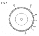
- Figure 1 shows a grinding wheel 10 including segmented wheel chips 11.
- the grinding wheel 10 is configured so that a plurality of arc-shaped wheel chips 11 each composed of an abrasive grain layer 12 and a foundation layer 13 are arranged on an outer circumferential surface of a disc-like core 14 made of a metal such as iron, aluminum or the like, a resin or the like and are adhered by an adhesive to the core 14 at bottom surfaces of the foundation layers 13.
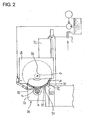
- the grinding wheel 10 is attached at the core 14 to a wheel spindle 32 which is carried by a wheel head 31 of a grinding machine 30 shown in Figure 2 , to be drivingly rotatable about an axis O.
- a workpiece W is drivingly rotatably supported by a workpiece support device 33 of the grinding machine 30.
- the advance movement of the wheel head 31 brings a grinding surface 15 formed on the abrasive grain layers 12 of the grinding wheel 10, into contact with the workpiece W at a grinding point P, so that the outer surface of the workpiece W is ground.
- each wheel chip 11 the abrasive grain layer 12 in which superabrasive gains are bonded by a vitrified bond is formed on the outer circumferential side, and the foundation layer 13 is placed on the inner side of the abrasive grain layer 12 to be formed bodily therewith.
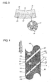
- Figure 3 shows the arc-shaped wheel chip 11, the abrasive grain layer 12 of which is configured by bonding with the vitrified bond 17 the superabrasive grains 16 such as CBN, diamond or the like to the depth of 3 to 7 mm. It may be the case that particles such as aluminum oxide (Al 2 O 3 ) or the like which replace those of superabrasive grains are mixed as aggregate into the abrasive grain layer 12 for adjustment of concentration.
- Al 2 O 3 aluminum oxide
- the foundation layer 13 is configured by bonding foundation particles 19 with the vitrified bond 17 to the depth of 2 to 4 mm. Because with the use of the vitrified bond 17, the property being porous improves the capability of discharging grinding chips thereby to enhance the sharpness, the grinding can be performed at an excellent accuracy of surface roughness and in a little quantity of the grinding wheel wear.
- bonding agent a resin bond, a metal bond or the like may be used instead of the vitrified bond 17.
- a plurality of oblique grooves 20 of the width b inclined relative to the wheel circumferential direction are provided on the grinding surface 15 of the grinding wheel 10 in such an arrangement that at least one oblique groove 20 vertically crosses the grinding point P independently of the rotational phase of the grinding wheel 10. Because the oblique groove 20 crosses the grinding point P at all times in this way, a dynamic pressure which the coolant supplied to the grinding point P generates between the grinding surface 15 and the workpiece W is released from both of an upper side and a lower side of the grinding point P.
- Each wheel chip 11 has the same width as the width of the outer circumferential surface of the core 14 and is arcuately curved to make the inner circumferential surface of the foundation layer 13 equal in curvature to the outer circumferential surface of the core 14.
- the opposite ends 24, 25 in the wheel circumferential direction of the wheel chip 11 are inclined by an inclination angle ⁇ relative to the wheel circumferential direction, and the foundation layer 13 has a protruding portion 23 formed by being protruded by a predetermined length c from the abrasive grain layer 12 in the wheel circumferential direction.
- an oblique groove 20 is formed between the abrasive grain layers 12 of the adjoining wheel chips 11, so that it can be realized to make at least one oblique groove 20 cross the grinding point P independently of the rotational phase of the grinding wheel 10.
- oblique grooves 20 which effectively prevent the generation of a dynamic pressure in the coolant supplied to the grinding point P and which can secure high grinding accuracy and a long wheel life. It is desirable that at least one, preferably two or more oblique grooves 20 are made to cross the grinding point P within the width of the workpiece W, that is, within the axial length of the grinding point P independently of the rotational phase of the grinding wheel 10.
- a groove circumferential width c (equal to the predetermined length c by which the protruding portion 23 protrudes in the wheel circumferential direction) being the width of the oblique groove 20 in the wheel circumferential direction is desired to be short for the reason that the interval of the superabrasive grains 16 exposed to the grinding surface 15 is widened by the groove circumferential width c.
- the number of the grooves would be better in light of decreasing the number of the wheel chips 11.
- a narrow interval of the oblique grooves 20 would make the circumferential length of the wheel chips 11 short and would cause the strength of the wheel chips 11 to be weakened, and therefore, the pitch in the wheel circumferential direction of the oblique grooves 20 is desired to be long.
- the inclination angle ⁇ is the angle which the oblique grooves 20 make with the lateral surface 21 of the abrasive grain layers 12, that is, with respect to the wheel circumferential direction, and the axial length of the grinding point P is 15 mm equal to the width of the workpiece W.
- the width b in the groove normal direction of the oblique groove 20 is desired to be set as 1 mm or so.
- the relation between the groove circumferential width c and the inclination angle ⁇ of the oblique groove 20 is represented in Figure 6 . Where the inclination angle ⁇ is set to be larger than 15 degrees or so, the groove circumferential width c becomes narrow, so that the stretch of the interval between the superabrasive grains 16 which stretch is made by the oblique groove 20 can be suppressed to be small.
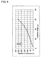
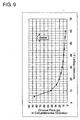
- the oblique grooves 20 of e.g., two in number are made to cross the grinding point P with the same axial length as the width of the workpiece W independently of the rotational phase of the grinding wheel 10, the relation between the inclination angle ⁇ and the number n of the oblique grooves 20 is represented as shown in Figure 8 , the relation between the inclination angle ⁇ and the pitch p in the wheel circumferential direction of the oblique grooves 20 is represented as shown in Figure 9 , and the relation between the inclination angle ⁇ and the reduction percentage at which the area of the grinding surface 15 is reduced by the oblique grooves 20 is represented as shown in Figure 10 .
- the specifications of the oblique grooves 20 are determined to make two oblique grooves 20 cross the grinding point P within the width of the workpiece W, that is, within the axial length of the grinding point P independently of the rotational phase of the grinding wheel 10, and one example of the specifications so determined is 1 mm in the groove width b, 15 degrees in the inclination angle ⁇ , 39 in the number n, and about 28.1 mm in the circumferential pitch p.
- each wheel chip 11 has the opposite ends 24, 25 in the wheel circumferential direction inclined 15 degrees relative to the wheel circumferential direction, is 28.1 mm in the circumferential length, is provided at the foundation layer 13 with the protruding portion 23 protruding from the abrasive grain layer 12 in the wheel circumferential direction, has the width of, e.g., 30 mm which is double the width of the workpiece W, and takes the shape of being arcuately curved to make the inner circumferential surface of the foundation layer 13 equal in curvature to the outer circumferential surface of the core 14.
- the protruding portion 23 protrudes 1 mm from the end surface of the abrasive grain layer 12 perpendicularly of the end surface.
- a lower mold 43 is fitted in an inside bottom portion of a rhombic outer mold 40 which has lateral walls corresponding to both parallel lateral surfaces 21, 22 of the wheel chip 11 and end walls 41, 42 inclined by the inclination angle ⁇ relative to the wheel circumferential direction and corresponding to the opposite ends 24, 25, and an arc-shape concave surface 44 corresponding to the arc surface of the wheel chip 11 for forming the outer diameter of the grinding wheel 10 is formed on an upper surface of the lower mold 43.
- One end wall 41 is provided with a step portion 41 s and a concave wall 41 u for forming the protruding portion 23, and a detachable block 47 is fitted in the step portion 41 s and the concave wall 41 u.
- the surface of the block 47 so fitted and the interior surface of the one end wall 41 are formed to share a common flat surface.
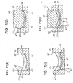
- Abrasive grain layer powder 45 being a mixture of superabrasive grains 16, a vitrified bond 17, aggregate (not shown) and the like which constitute the abrasive grain layer 12 is filled on the lower mold 43, and leveling is done to make the abrasive grain layer powder 45 uniform in thickness (step 61 in Figure 12 ).
- a pressing mold being a first upper mold 46 is moved down along the interior surface of the outer mold 40, whereby the abrasive grain layer powder 45 is provisionally pressed to preform the abrasive grain layer 12 to an arc shape (step 62).
- the block 47 is taken out of the step portion 41 s and the concave wall 41 u of the end wall 41, whereby as shown in Figure 11(c) , the step portion 41 s and the concave wall 41 u come to appear on the one end wall 41 of the outer mold 40 at a position facing the edge of the inner circumferential surface of the abrasive grain layer 12 having been preformed on the lower mold 43.
- An end wall 41l below the step portion 41 s of the one end wall 41, the other end wall 42 and the both lateral walls surround the lower mold 43 and the preformed abrasive grain layer 12, and the concave wall 41 u above the step portion 41 s recedes outside by the width b in the groove normal direction of the oblique groove 20 from the end wall 41l below the step portion 41 s.
- the foundation layer powder 50 including foundation particles 19 is filled on the upper side of the abrasive grain layer 12 press-formed provisionally and is leveled so that the foundation layer powder 50 becomes uniform in thickness (step 63).
- a second upper mold 51 which has an arc surface formed at an end to be the same in diameter as the core 14 is lowered along the interior surface of the outer mold 40 to press the foundation layer powder 50 and the abrasive grain layer powder 45 at a time.
- the foundation layer 13 is bodily press-formed to be placed on the inner side of the abrasive grain layer 12, and the protruding portion 23 is formed at a portion which the foundation layer 13 protrudes from the abrasive grain layer 12 in the wheel circumferential direction, whereby the arc-shape wheel chip 11 is formed (step 64).
- the second upper mold 51 is moved up, and the arc-shape wheel chip 11 is taken out of the outer mold 40 and the lower mold 43 (step 65).
- a plurality of green wheel chips 11 are manufactured in the same manner as described above.
- the wheel chips 11 are baked in a furnace (step 66), whereby the manufacturing of the wheel chips 11 are completed Thirty-nine wheel chips 11 so baked are adhered to the core 14 in such an arrangement that the oblique groove 20 is formed between adjoining wheel chips 11 by contacting the protruding portion 23 with the foundation layer 13 of an adjoining wheel chip 11 and that at least two oblique grooves 20 cross the grinding point P independently of the rotational phase of the grinding wheel 10 (step 67). Because the wheel chips 11 are not machined after the baking for the purpose of cutting the obvious grooves 20, it does not occur that the retention force of the superabrasive grains 16 is weakened by such machining.
- the grinding wheel 10 is drivingly rotated with the core 14 attached to the wheel spindle 32 which is rotatably supported by the wheel head 31 of the grinding machine 30 shown in Figure 2 , while the workpiece W is drivingly rotated with itself supported by the workpiece support device 33 composed of a work head and a foot stock.
- Coolant is supplied from a coolant nozzle 35 attached to a wheel cover 34, toward the grinding point P between the grinding wheel 10 and the workpiece W.
- the wheel head 31 is fed toward the workpiece W, whereby the workpiece W is ground with the grinding wheel 10.
- a grinding wheel of 350mm in outer diameter wherein the abrasive grain layers 12 were formed by bonding CBN abrasive grains of #120 in grain size with the vitrified bond 17 in the concentration of 150 and wherein the wheel chips 11 were formed by bodily placing the foundation layers 13 with no superabrasive grains contained therein, on the inner sides of the abrasive grain layers 12 and were adhered to the steel core 14[,].
- the obliquely grooved grinding wheel 10 was used wherein thirty-nine oblique grooves 20 each being 1 mm in the groove width b, 6 mm in the groove depth h and 15 degrees in the inclination angle ⁇ were grooved on the outer circumferential grinding surface 15 of the aforementioned grinding wheel[,].
- the foundation layer 13 is press-formed by using the outer mold 40 having the step portion 41s and the concave wall 41u formed thereon, the outer mold 40 does not need to have the step portion 41 s and the concave wall 41 u formed thereon.
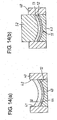
- abrasive grain layer powder 45 is provisionally pressed at step 62 shown in Figure 11(b) to provisionally form the abrasive grain layer 12 to an arc shape by moving the pressing mold being the first upper mold 46 down along the interior of the outer mold 40, the first upper mold 46 is moved up, the foundation layer powder 50 including the foundation particles 19 is filled on the upper side of the provisionally press-formed abrasive grain layer 12, and the foundation layer power 50 is leveled to become uniform in thickness (refer to Figure 14(a) ).
- the second upper mold 52 which has an arc surface formed at an end to be the same in diameter as the core 14 is moved down along the interior of the outer mold 40 to press the foundation layer powder 50 and the abrasive grain layer powder 45 at a time.
- an arc-shaped wheel chip 11 in which the foundation layer 13 is bodily press-formed to be placed on the inner side of the abrasive grain layer 12 and which has opposite ends in the wheel circumferential direction parallel and inclined by the inclination angle ⁇ relative to the wheel circumferential direction.
- the second upper mold 52 is moved up, and the wheel chip 11 is taken out of the outer mold 40 and the lower mold 43.
- the wheel chips 11 are adhered to the core 14, as shown in Figure 15 .
- Each wheel chip 11 has been press-formed to have their opposite ends in the wheel circumferential direction parallel to each other, and thus, in the stated that it is adhered to the core 14, the foundation layer 13 protrudes on the small diameter side from the abrasive grain layer 12 in the wheel circumferential direction to form protruding portions 23. Accordingly, when the wheel chips 11 are adhered to the core 14 with adjoining foundation layers 13 being in contact, an oblique groove 20 inclined by the inclination angle ⁇ relative to the wheel circumferential direction is formed between adjoining wheel chips 11.
- each foundation layer 13 is made to protrude on the small diameter side from the abrasive grain layer 12 in the wheel circumferential direction.
- each wheel chip 11 has the protruding portion 23 which protrudes one end in the wheel circumferential direction of the foundation layer 13 stepwise from the abrasive grain layer 12 in the wheel circumferential direction
- the foundation layer 13 may have protruding portions 23 formed at opposite ends thereof in the wheel circumferential direction to protrude stepwise from the abrasive grain layer 12 in the wheel circumferential direction, as shown in Figure 16 .
- each foundation layer 13 has the protruding portion 23 formed by being protruded stepwise from the abrasive grain layer 12 in the wheel circumferential direction
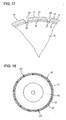
- each wheel chip 11 may have protruding portions 23 which as shown in Figure 17 , are formed at the foundation layer 13 by being inclined so that at least one end surface in the wheel circumferential direction is protruded longer in the wheel circumferential direction on the smaller diameter side.
- the plurality of wheel chips 11 are adhered to the core 14 in such an arrangement that an oblique groove 20 is formed between adjoining abrasive grain layers 12 by contacting the protruding portion 23 of each wheel chip 11 with the foundation layer 13 of an adjoining wheel chip 11 and that at least one oblique groove 20 crosses the grinding point P independently of the rotational phase of the grinding wheel 10.
- the width of the workpiece W is narrower than the width of the grinding wheel 10, in which case the specifications of the oblique grooves 20 are calculated on the assumption that the axial length of the grinding point P is equal to the width of the workpiece W.
- the width of the workpiece W is wider than the width of the grinding wheel 10, in which case the specifications of the oblique grooves 20 may be calculated on the assumption that the axial length of the grinding point P is equal to the width of the grinding wheel 10.
- the plurality of baked wheel chips 11 are arranged so that at least two oblique grooves 20 cross the grinding point P independently of the rotational phase of the grinding wheel 10, an arrangement may be made to make at least one oblique groove 20 cross the grinding point P.
- a grinding wheel 10 including segmented wheel chips 11 manufactured in a manufacturing method in the example differs from the grinding wheel in the first embodiment in a respect that as shown in Figure 18 , oblique grooves 20 pass through the foundation layers 13 to reach the core 14.
- Other constructions are the same as described above and therefore, are omitted from being described.
- a plurality of wheel chips 11 are press-formed to take the form of a parallelogram and are adhered to the outer circumference of a core 14 each with a clearance relative to the next thereto so that facing oblique end surfaces of adjoining wheel chips 11 form inner side walls of an oblique groove therebetween.
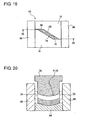
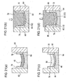
- a press-forming mold 60 for forming the wheel chips 11 is provided with a lower mold 64 having as an upper surface a grinding surface forming wall 62 being an arc shape corresponding to the grinding surface 15 of the wheel chip 11 to be formed, a one-side outer mold 70 provided with a one-side lateral surface forming wall 66 corresponding to a one-side lateral surface parallel to the wheel circumferential direction of the wheel chip 11 to be formed and a one-side end surface forming wall 68 corresponding to a one-side end surface in the wheel circumferential direction (an end surface ahead in the wheel rotational direction) of the wheel chip 11 inclined relative to the wheel circumferential direction, an other-side outer mold 76 provided with an other-side lateral surface forming wall 72 corresponding to an other-side lateral surface parallel to the wheel circumferential direction of the wheel chip 11 to be formed and an other-side end surface forming wall 74
- the lower mold 64 and the outer molds 70, 76 are firmly secured to a frame member 80.
- the lateral surface forming walls 66, 72 and the end surface forming walls 68, 74 of the outer molds 70, 76 are formed by, e.g., machining or the like.
- abrasive grain layer powder 45 being a mixture of superabrasive grains, a bonding agent, aggregate and the like which constitute the abrasive grain layer 12 is filled on the lower mold 64, and leveling is done to make the abrasive grain layer powder 45 uniform in thickness.
- the foundation layer powder 50 including the foundation particles 19 is filled on the upper side of the provisionally press-formed abrasive grain layer powder 45, and leveling is carried out to make the foundation layer powder 50 uniform in thickness.
- the upper mold 78 having as an end an arc surface formed to be equal in diameter (e.g., R175) to the core 14 is moved down along the interiors of the outer molds 70, 76 to press the foundation layer powder 50 and the abrasive grain layer powder 45 at a time, whereby the foundation layer 13 is formed to be placed on the inner side of the abrasive grain layer 12.
- the upper mold 78 is moved up, and the wheel chip 11 is taken out of the outer molds 70, 76 and the lower mold 64, whereby a green wheel chip 11 is formed.
- a plurality of green wheel chips 11 are manufactured in the same manner as described above.
- the green wheel chips 11 are baked in a furnace. Where a vitrified bond is used as the bonding agent, the baking is carried out in a range of, e.g., 700 to 1000 °C. In this way, the manufacturing of the wheel chips 11 is completed, whereby as shown in Figure 22 , the wheel chips 11 are formed each of which takes the form of a parallelogram as viewed from above and which is curved like an arc shape as viewed from one side.
- the plurality of wheel chips 11 are adhered in turn to the outer circumference of the disc-like core 14 for the grinding wheel 10 in such an arrangement that a clearance becoming an oblique groove 20 of a groove width b is provided between a rearward end surface 82 of a wheel chip 11 adjoining on the forward side in the wheel rotational direction and a forward end surface 84 of another wheel chip 11 adjoining to the wheel chip 11 on the rearward side in the wheel rotational direction.
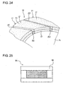
- the grinding wheel 10 is formed in which the oblique grooves 20 reach the core 14, as shown in Figure 24 .
- the press-forming forms the wheel chips 11 each having, in addition to the grinding surface 15 of an arc shape, oblique end surfaces 82, 84 which constitute inner side walls of the oblique groove 20 when adhered to the core 14. Therefore, only by adhering the wheel chips 11 to the core 14 with the clearance provided between the facing end surfaces 82, 84 of adjoining wheel chips 11, it becomes possible to easily form the grinding wheel with the oblique grooves 20.
- the oblique grooves 20 are not cut by machining on the difficult-to-machine grinding surface 15 of the baked wheel chips 11 having been adhered to the core 14, it can be realized to provide an obliquely grooved grinding wheel with which it does not occur that the retention force of the superabrasive grains is weakened by machining and which is possible to shorten the manufacturing period of time and low in cost.
- the operation of the grinding wheel 10 manufactured in the aforementioned manufacturing method is the same as that in the first embodiment, and therefore, description regarding the operation is omitted.
- a grinding wheel 10 including segmented wheel chips 11 manufactured in a manufacturing method in this example is the same as the grinding wheel in the first example shown in Figure 18 , and therefore, description regarding the grinding wheel 10 is omitted.
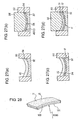
- a plurality of wheel chips 11 are adhered to the outer circumference of the core 14 in such an arrangement that they are provided with clearances therebetween and are inclined relative to the wheel circumferential direction to make the facing lateral surfaces of adjoining wheel chips 11 form inner side walls of an oblique groove 20, and projecting portions of the wheel chips which project out beyond the width of the core 14 are eliminated by machining.
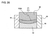
- a lower mold 92 is fitted at an inner bottom portion of a rectangular outer mold 90, and as shown in Figure 26 , an arc-shaped concave surface 94 for press-forming an arc shape surface of a wheel chip 11 constituting the outer diameter of the grinding wheel is formed on the upper surface of the lower mold 92.
- an upper mold 96 movable downward along the interior of the outer mold.
- An arc surface 98 of a diameter (e.g., R290 mm) which is somewhat greater than the diameter (e.g., R175 mm) of the core 14 is formed on an end of the upper mold 96.
- abrasive grain layer powder 45 being a mixture of superabrasive grains, a bonding agent, aggregate and the like which constitute the abrasive grain layer 12 is filled on the upper side of the lower mold 92, and leveling is carried out to make the abrasive grain layer powder 45 uniform in thickness.
- the upper mold 96 is moved down into the outer mold 90, and the abrasive grain layer powder 45 is provisionally pressed to preform the abrasive grain layer 12 to an arc shape.
- foundation layer powder 50 including foundation particles 19 is filled on the upper side of the provisionally press-formed abrasive grain layer powder 45, and leveling is carried out to make the foundation layer powder 50 uniform in thickness.
- the upper mold 96 is moved down into the outer mold 90 to press the foundation layer powder 50 and the abrasive grain layer powder 46 at a time, and the foundation layer 13 is bodily formed to be placed on the inner side of the abrasive grain layer 12, whereby a wheel chip 11 of an arc shape is press-formed.
- a contact surface 101 at which the foundation layer 13 of the wheel chip 11 is to contact the outer circumference of the core 14 is formed to R 290 mm determined by the diameter at the end of the upper mold 96.
- the upper mold 96 is moved up, and the wheel chip 11 is taken out of the outer mold 90 and the lower mold 92.
- the wheel chips 11 are baked in a furnace.
- a vitrified bond is used as the bonding agent as is the case of the present example
- the baking is carried out in a range of, e.g., 700 to 1000 °C.
- the wheel chips 11 are formed each of which has the contact surface 101 of the diameter R290 mm and a pair of mutually parallel end surfaces 100 and takes the form of a rectangular as viewed from above and an arc shape as viewed from one side.
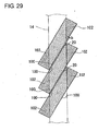
- the baked wheel chips 11 are adhered to the outer circumference of the core 14 in such an arrangement that the lateral end surfaces 100 of each wheel chip 11 are inclined relative to the wheel circumferential direction and that a clearance of a groove width b is provided to make the facing lateral end surfaces 100 of the wheel chips 11 form inner side walls of an oblique groove 20.
- the wheel chips 11 it is possible to press-form the wheel chips 11 easily without using a special press-forming mold. Further, by making the contact surface 101 of each wheel chip 11 as an arc surface of the diameter which is greater than the outer diameter of the core 14, it becomes possible to adhere the wheel chips 11 to the outer circumference of the core 14 in such an arrangement that the clearance generated between the contact surface 101 and the outer circumferential surface of the core 14 is suppressed to be small and that the lateral end surfaces 100 of each wheel chip 11 are inclined relative to the wheel circumferential direction.
- the projecting portions 102 projecting out beyond the width of the core 14 are eliminated by machining, the oblique grooves 20 provided on the grinding surface 15 of the wheel chips 11 are not cut by machining. Thus, it does not occur that the retention force of the superabrasive grains on the grinding surface 15 which are used mainly during grinding operations is not weakened by machining.
- the operation of the grinding wheel 10 manufactured in the aforementioned manufacturing method is the same as that in the first embodiment, and therefore, description regarding the operation of the grinding wheel is omitted.
- the diameter of the contact surface 101 of each wheel chip is set to R290 mm for the diameter R175 mm of the core 14, the present invention is not limited to these values. It is possible to choose these values properly in dependence on the angle at which the wheel chips are inclined as well as on the diameter of the core.
- Applicability is directed to an obliquely grooved grinding wheel for effectively leading coolant along oblique grooves to a grinding point and the use in manufacturing the obliquely grooved grinding wheel at a low cost without weakening the retention force of superabrasive grains on a grinding surface.
Landscapes
- Engineering & Computer Science (AREA)
- Mechanical Engineering (AREA)
- Manufacturing & Machinery (AREA)
- Polishing Bodies And Polishing Tools (AREA)
Claims (6)
- Herstellungsverfahren für eine Schleifscheibe (10) mit schrägen Nuten, in der eine Vielzahl von Scheibenplättchen (11), die jeweils aus einer Schicht (12) abrasiver Körner zusammengesetzt ist, die stark abrasive Körner (16) und eine Grundschicht (13) enthält, an einen Kern (14) angehaftet sind, der an einer Scheibenspindel (32) angebracht ist, die durch einen Scheibenkopf (31) einer Schleifmaschine (30) getragen ist, um angetrieben um eine Drehachse drehbar zu sein, und in der eine Schleiffläche (15), die auf den Schichten (12) der abrasiven Körner ausgebildet ist, ein Werkstück (W) in Berührung mit einem Schleifpunkt schleift, das angetrieben drehbar durch ein Werkstückstützgerät der Schleifmaschine (30) gestützt ist, wobei das Verfahren umfasst:einen Scheibenplättchenausbildungsschritt, ungesinterte Scheibenplättchen (11) auszubilden, die jeweils gegenüberliegende Enden in einer Umfangsrichtung der Scheibe aufweisen, die relativ zu der Umfangsrichtung der Scheibe geneigt sind;einen Sinterschritt, die ungesinterten Scheibenplättchen (11) zu sintern, um gesinterte Scheibenplättchen (11) auszubilden; undeinen Anhaftungsschritt, die Vielzahl der gesinterten Scheibenplättchen (11) so an dem Kern (14) anzuhaften, dass eine schräge Nut (20) zwischen anliegenden Schichten (12) abrasiver Körner ausgebildet ist,dadurch gekennzeichnet, dassder Scheibenplättchenausbildungsschritt das Ausbilden der gegenüberliegenden Enden (24, 25) in der Umfangsrichtung der Scheibe derart aufweist, dass sie relativ zu der Umfangsrichtung der Scheibe geneigt sind, und das Ausbilden eines vorstehenden Abschnitts (23) durch das Vorstehenlassen der Grundschicht (13) von der Schicht (12) der abrasiven Körner in der Umfangsrichtung der Scheibe; undder Anhaftungsschritt das Anhaften der Vielzahl der gesinterten Scheibenplättchen (11) an dem Kern (14) derart hat, dass die schräge Nut (20) zwischen den anliegenden Schichten (12) abrasiver Körner durch das Berühren des vorstehenden Abschnitts (23) von jedem gesinterten Scheibenplättchen (11) mit der Grundschicht (13) eines anliegenden Scheibenplättchen (11) ausgebildet ist.
- Herstellungsverfahren nach Anspruch 1, wobei der Scheibenplättchenausbildungsschritt umfasst:Bereitstellen einer Pressausbildungsform (60), die mit einer bogenförmigen Schleifflächenausbildungswand (62) zum Ausbilden der Schleiffläche (50) des Scheibenplättchens (11) bereitgestellt ist, wobei beide seitlichen Oberflächenausbildungswände (72) von der Schleifflächenausbildungswand (62) in einer aufrechten Richtung aufstehen und beide Seitenflächen (21, 22) parallel zu der Umfangsrichtung der Scheibe das Scheibenplättchen (11) ausbilden, und vordere und rückwärtige Endflächenausbildungswände (74), die von der Schleifflächenausbildungswand (62) in der aufrechten Richtung aufstehen und schräg beide Seitenflächenausbildungswände (72) kreuzen, um eine vordere Endfläche (25) und eine rückwärtige Endfläche (24) in der Drehrichtung der Scheibe des Scheibenplättchen (11) auszubilden, die relativ entsprechend zu der Umfangsrichtung der Scheibe geneigt sind;Füllen der Pressausbildungsform (60) mit einem Pulver für eine Schicht (12) abrasiver Körner, das ein Gemisch aus verschiedenen stark abrasiven Körnern (16) und einem Bond-Mittel (17) ist;Einfüllen eines Grundschichtpulvers (50), das ein Gemisch aus Grundpartikeln und einem Bond-Mittel (17) ist, das auf dem Pulver (45) der Schicht abrasiven Körner zu platzieren ist;Pressausbilden des Pulvers (45) der Schicht der abrasiven Körner und des Grundschichtpulvers (50) in einer körperlichen Weise zu einer kreisförmigen Form; undHerausnehmen der Schicht (12) der abrasiven Körner und der Grundschicht (13) aus der Pressausbildungsform (60), die körperlich durch die Pressausbildungsform (60) ausgebildet sind, um die ungesinterten Scheibenplättchen (11) auszubilden, die jeweils die Schleiffläche (15), die beiden Seitenflächen (21, 22), die vordere Endfläche (25) und die rückwärtige Endfläche (24) aufweisen; undder Anhaftungsschritt umfasst:Anhaften der entsprechenden gesinterten Scheibenplättchen (11) an dem äußeren Umfang des Kerns (14) mit einem Freiraum zwischen der rückwärtigen Endfläche (24) eines Scheibenplättchen (11), das voraus in der Drehrichtung der Schleifscheibe (10) angrenzt und der vorderen Endfläche (25) eines Scheibenplättchens (11), das in der Drehrichtung der Schleifscheibe (10) an das Scheibenplättchen (11) dahinter angrenzt.
- Schleifscheibe (10) mit einer schrägen Nut, in der eine Vielzahl von Scheibenplättchen (11) die jeweils aus einer Schicht (12) abrasiver Körner, die stark abrasive Körner (16) enthält, und einer Grundschicht (13) zusammengesetzt ist, an einem Kern (14) angehaftet ist, der an einer Scheibenspindel (32) angebracht ist, die durch einen Scheibenkopf (31) einer Schleifmaschine (30) gehalten ist, um angetrieben um eine Drehachse drehbar zu sein, und in der eine Schleiffläche (15), die auf den Schichten (12) der abrasiven Körner ausgebildet ist, ein Werkstück (W) in Berührung mit einem Schleifpunkt schleift, das angetrieben drehbar durch ein Werkstück-(W)-Stützgerät der Schleifmaschine (30) gestützt ist, wobei:das Scheibenplättchen (11) beide Enden in einer Umfangsrichtung der Scheibe relativ zu der Umfangsrichtung der Scheibe geneigt hat;dadurch gekennzeichnet, dassdie Grundschicht (13) einen vorstehenden Abschnitt (23) aufweist, der ausgebildet ist, von der Schicht (12) der abrasiven Körner in der Umfangsrichtung der Scheibe vorzustehen; unddie Vielzahl der Scheibenplättchen (11) an dem Kern (14) so angehaftet sind, dass der vorstehende Abschnitt (23) die Grundschicht (13) eines angrenzenden Scheibenplättchen (11) berührt, um eine schräge Nut (20) zwischen den angrenzenden Schichten (12) der abrasiven Körner auszubilden.
- Schleifscheibe (10) mit einer schrägen Nut nach Anspruch 3, wobei:das Scheibenplättchen (11) den vorstehenden Abschnitt (23) aufweist, der durch das Vorstehenlassen von zumindest einem Ende der Grundschicht (13) in der Umfangsrichtung der Scheibe der Schicht (12) der abrasiven Körner stufenweise in der Umfangsrichtung der Scheibe ausgebildet ist; undjedes Scheibenplättchen (11) an dem Kern (14) angehaftet ist, wobei der vorstehende Abschnitt (23) die Grundschicht (13) eines angrenzenden Scheibenplättchen (11) berührt.
- Schleifscheibe (10) mit einer schrägen Nut nach Anspruch 3, wobei die vorstehenden Abschnitte (23) ausgebildet sind, an einer Seite kleinen Durchmessers der Grundschicht (13) von der Schicht (12) der abrasiven Körner in der Umfangsrichtung der Scheibe durch Pressausbilden des Scheibenplättchen (11) vorzustehen, damit beide Endflächen davon in der Umfangsrichtung der Scheibe parallel zueinander sind.
- Schleifscheibe (10) mit einer schrägen Nut nach Anspruch 3, wobei:das Scheibenplättchen (11) den vorstehenden Abschnitt (23) aufweist, der durch das Neigen von zumindest einer Endfläche in der Umfangsrichtung der Scheibe ausgebildet ist, damit er an einer Seite kleinen Durchmessers in der Umfangsrichtung der Scheibe weiter vorsteht; undjedes Scheibenplättchen (11) an dem Kern (14) angehaftet ist, wobei der vorstehende Abschnitt (23) die Grundschicht (13) eines angrenzenden Scheibenplättchens (11) berührt.
Applications Claiming Priority (3)
| Application Number | Priority Date | Filing Date | Title |
|---|---|---|---|
| JP2006300415 | 2006-11-06 | ||
| JP2007183240A JP5100225B2 (ja) | 2006-11-06 | 2007-07-12 | 傾斜溝入り砥石及びその製造方法 |
| PCT/JP2007/070720 WO2008056539A1 (en) | 2006-11-06 | 2007-10-24 | Grindwheel with sloping groove and process for fabricating the same |
Publications (3)
| Publication Number | Publication Date |
|---|---|
| EP2095908A1 EP2095908A1 (de) | 2009-09-02 |
| EP2095908A4 EP2095908A4 (de) | 2011-01-05 |
| EP2095908B1 true EP2095908B1 (de) | 2012-05-02 |
Family
ID=39364362
Family Applications (1)
| Application Number | Title | Priority Date | Filing Date |
|---|---|---|---|
| EP07830454A Ceased EP2095908B1 (de) | 2006-11-06 | 2007-10-24 | Schleifscheibe mit schrägen nuten und herstellungsverfahren dafür |
Country Status (5)
| Country | Link |
|---|---|
| US (1) | US8182318B2 (de) |
| EP (1) | EP2095908B1 (de) |
| JP (1) | JP5100225B2 (de) |
| CN (1) | CN101528419B (de) |
| WO (1) | WO2008056539A1 (de) |
Families Citing this family (20)
| Publication number | Priority date | Publication date | Assignee | Title |
|---|---|---|---|---|
| KR20100138359A (ko) * | 2009-06-25 | 2010-12-31 | 신한다이아몬드공업 주식회사 | 다이아몬드 공구 |
| TWI453089B (zh) * | 2010-08-16 | 2014-09-21 | Saint Gobain Abrasives Inc | 對包含超級磨料材料的工件進行磨削之方法 |
| USD710407S1 (en) * | 2011-10-04 | 2014-08-05 | Inland Diamond Products Company | Segmented profiled wheel |
| USD708236S1 (en) * | 2011-10-04 | 2014-07-01 | Inland Diamond Products Company | Segmented profiled wheel |
| USD708235S1 (en) * | 2011-10-04 | 2014-07-01 | Inland Diamond Products Company | Segmented profiled wheel |
| USD710408S1 (en) * | 2011-10-04 | 2014-08-05 | Inland Diamond Products Company | Segmented profiled wheel |
| US9050706B2 (en) * | 2012-02-22 | 2015-06-09 | Inland Diamond Products Company | Segmented profiled wheel and method for making same |
| CN102658528A (zh) * | 2012-02-24 | 2012-09-12 | 浙江工业大学 | 一种分级结构化复合弹性研抛盘 |
| SG11201510027RA (en) * | 2013-06-07 | 2016-01-28 | 3M Innovative Properties Co | Method of forming a recess in a substrate, abrasive wheel, and cover |
| US10160096B2 (en) * | 2014-10-31 | 2018-12-25 | Jtekt Corporation | Grinding wheel and method for manufacturing grinding wheel |
| CN104440626A (zh) * | 2014-12-04 | 2015-03-25 | 泰兴市和庆机械配件厂 | 一种纤维网片放置系统 |
| CN105215795B (zh) * | 2015-08-26 | 2017-11-07 | 朱旭光 | 非晶合金产品异形面加工方法 |
| CN105437093A (zh) * | 2016-01-07 | 2016-03-30 | 河北工业大学 | 一种风扇散热式砂轮 |
| CN106181798A (zh) * | 2016-08-30 | 2016-12-07 | 洛阳希微磨料磨具有限公司 | 一种砂轮磨具 |
| CN106891279B (zh) * | 2017-03-07 | 2019-03-01 | 郑州磨料磨具磨削研究所有限公司 | 异形砂轮成型模具及其压头组件和压头 |
| EP3600771B1 (de) * | 2017-03-31 | 2022-03-30 | B & J Rocket Sales AG | Verbessertes schleifrad |
| JP6817161B2 (ja) * | 2017-07-07 | 2021-01-20 | 三菱重工業株式会社 | 研削砥石及び研削砥石の製造方法 |
| KR102700969B1 (ko) * | 2020-01-13 | 2024-09-02 | 징신 송 | 전기도금 스틸와이어 치형 조합식 연삭휠 |
| EP3892421B1 (de) * | 2020-04-07 | 2023-01-25 | VK Investment GmbH | Schleifpad, schleifpadträgerkörper und schleifscheibe |
| CN113649891B (zh) * | 2021-10-20 | 2021-12-17 | 江苏学霖电缆科技有限公司 | 一种电力电缆附件橡胶制品打磨装置 |
Family Cites Families (17)
| Publication number | Priority date | Publication date | Assignee | Title |
|---|---|---|---|---|
| US3916579A (en) * | 1975-02-10 | 1975-11-04 | Tunco Manufacturing Inc | Slotted abrasive wheel |
| JPS61257777A (ja) * | 1985-03-14 | 1986-11-15 | Osaka Daiyamondo Kogyo Kk | 鉄ベ−ス層付カツタ−セグメント |
| JPS62278207A (ja) * | 1986-05-26 | 1987-12-03 | Yokota Seiki Seisakusho:Kk | ダイヤモンドプレ−トソ−のチツプの製造方法 |
| US5307826A (en) * | 1992-03-30 | 1994-05-03 | Ilya Iosilevich | Automatic mascara dispensing eyelash curler |
| CN2136105Y (zh) * | 1992-09-26 | 1993-06-16 | 臧新建 | 加工中自然成槽的填充开槽砂轮 |
| US5611724A (en) * | 1995-12-01 | 1997-03-18 | General Electric Company | Grinding wheel having dead end grooves and method for grinding therewith |
| JPH09193024A (ja) * | 1996-01-16 | 1997-07-29 | Musashi Seimitsu Ind Co Ltd | 研削砥石 |
| KR100485846B1 (ko) * | 1997-05-09 | 2005-04-28 | 롬 앤드 하스 일렉트로닉 머티리얼스 씨엠피 홀딩스, 인코포레이티드 | 모자이크 폴리싱 패드 및 그와 관련된 방법 |
| JP4057176B2 (ja) * | 1998-12-15 | 2008-03-05 | 株式会社トプコン | 光学部材の研磨用工具とこれに用いられるピッチセグメント、及びそのピッチセグメントの成形型 |
| JP2000354969A (ja) | 1999-06-15 | 2000-12-26 | Katagiri Seisakusho:Kk | 超砥粒研削砥石 |
| US6105585A (en) * | 2000-01-07 | 2000-08-22 | Thomas; Marsha | Combination eyelash curler and eyeliner applicator |
| US6789551B2 (en) * | 2001-05-08 | 2004-09-14 | Irina Iosilevich | Eyelash separating, curling and coloring apparatus |
| JP4053019B2 (ja) * | 2003-04-21 | 2008-02-27 | 花王株式会社 | マスカラ付与装置 |
| CN2637101Y (zh) * | 2003-07-11 | 2004-09-01 | 方雅典 | 研磨绒碟 |
| JP2006142455A (ja) | 2004-11-24 | 2006-06-08 | Toyoda Van Moppes Ltd | 超砥粒砥石およびその製造方法 |
| JP5178205B2 (ja) * | 2005-12-28 | 2013-04-10 | 豊田バンモップス株式会社 | セグメント砥石およびその製造方法 |
| JP4999560B2 (ja) * | 2007-06-07 | 2012-08-15 | 豊田バンモップス株式会社 | 研削盤における砥石軸装置 |
-
2007
- 2007-07-12 JP JP2007183240A patent/JP5100225B2/ja not_active Expired - Fee Related
- 2007-10-24 CN CN2007800392468A patent/CN101528419B/zh not_active Expired - Fee Related
- 2007-10-24 WO PCT/JP2007/070720 patent/WO2008056539A1/ja not_active Ceased
- 2007-10-24 EP EP07830454A patent/EP2095908B1/de not_active Ceased
- 2007-10-24 US US12/446,313 patent/US8182318B2/en not_active Expired - Fee Related
Also Published As
| Publication number | Publication date |
|---|---|
| EP2095908A1 (de) | 2009-09-02 |
| EP2095908A4 (de) | 2011-01-05 |
| JP2008137147A (ja) | 2008-06-19 |
| WO2008056539A1 (en) | 2008-05-15 |
| US8182318B2 (en) | 2012-05-22 |
| CN101528419A (zh) | 2009-09-09 |
| US20100317267A1 (en) | 2010-12-16 |
| JP5100225B2 (ja) | 2012-12-19 |
| CN101528419B (zh) | 2012-10-31 |
Similar Documents
| Publication | Publication Date | Title |
|---|---|---|
| US8182318B2 (en) | Obliquely grooved grinding wheel and method for manufacturing the same | |
| US6692343B2 (en) | Superabrasive wheel for mirror finishing | |
| EP2193881B1 (de) | Keramisch gebundene Schleifscheibe | |
| KR20020020724A (ko) | 연삭 숫돌 | |
| EP2075090B1 (de) | Dynamisches druckfreigabeverfahren für eine schleifflüssigkeit in einem schleifverfahren, schleifverfahren unter anwendung des freigabeverfahrens und schleifstein zur verwendung in dem schleifverfahren | |
| JP2003300165A (ja) | セグメントタイプ砥石 | |
| CN112223134A (zh) | 一种树脂复合金属磨轮的制作方法及树脂复合金属磨轮 | |
| CN101522373B (zh) | 制造其磨削表面上具有凹陷的砂轮的方法 | |
| JP4948122B2 (ja) | 傾斜溝入り砥石 | |
| JP2001260032A (ja) | ビトリファイド砥石 | |
| JP5181799B2 (ja) | 砥石 | |
| JP5468110B2 (ja) | 凹部入り砥石の製造方法 | |
| JP2004181597A (ja) | メタルボンド砥石及びその製造方法 | |
| JP2008142796A (ja) | 複合砥石 | |
| JP3537367B2 (ja) | フライス工具 | |
| JP2008213102A (ja) | ろう付け研削砥石 | |
| JP2001150353A (ja) | ダイヤモンドブレード | |
| JP2004298969A (ja) | 超砥粒ブレード | |
| JPH11198047A (ja) | 砥 石 | |
| JP2005288626A (ja) | 切断砥石 | |
| JP2002239913A (ja) | カップ型回転砥石 |
Legal Events
| Date | Code | Title | Description |
|---|---|---|---|
| PUAI | Public reference made under article 153(3) epc to a published international application that has entered the european phase |
Free format text: ORIGINAL CODE: 0009012 |
|
| 17P | Request for examination filed |
Effective date: 20090325 |
|
| AK | Designated contracting states |
Kind code of ref document: A1 Designated state(s): AT BE BG CH CY CZ DE DK EE ES FI FR GB GR HU IE IS IT LI LT LU LV MC MT NL PL PT RO SE SI SK TR |
|
| DAX | Request for extension of the european patent (deleted) | ||
| RBV | Designated contracting states (corrected) |
Designated state(s): DE |
|
| A4 | Supplementary search report drawn up and despatched |
Effective date: 20101208 |
|
| RIC1 | Information provided on ipc code assigned before grant |
Ipc: B24D 7/18 20060101ALI20101202BHEP Ipc: B24D 18/00 20060101ALI20101202BHEP Ipc: B24D 7/10 20060101AFI20101202BHEP |
|
| REG | Reference to a national code |
Ref country code: DE Ref legal event code: R079 Ref document number: 602007022491 Country of ref document: DE Free format text: PREVIOUS MAIN CLASS: B24D0005000000 Ipc: B24D0007100000 |
|
| GRAP | Despatch of communication of intention to grant a patent |
Free format text: ORIGINAL CODE: EPIDOSNIGR1 |
|
| RIC1 | Information provided on ipc code assigned before grant |
Ipc: B24D 18/00 20060101ALI20111123BHEP Ipc: B24D 7/18 20060101ALI20111123BHEP Ipc: B24D 7/10 20060101AFI20111123BHEP |
|
| RTI1 | Title (correction) |
Free format text: OBLIQUELY GROOVED GRINDING WHEEL AND METHOD FOR MANUFACTURING THE SAME |
|
| GRAS | Grant fee paid |
Free format text: ORIGINAL CODE: EPIDOSNIGR3 |
|
| GRAA | (expected) grant |
Free format text: ORIGINAL CODE: 0009210 |
|
| AK | Designated contracting states |
Kind code of ref document: B1 Designated state(s): DE |
|
| REG | Reference to a national code |
Ref country code: DE Ref legal event code: R096 Ref document number: 602007022491 Country of ref document: DE Effective date: 20120705 |
|
| PLBE | No opposition filed within time limit |
Free format text: ORIGINAL CODE: 0009261 |
|
| STAA | Information on the status of an ep patent application or granted ep patent |
Free format text: STATUS: NO OPPOSITION FILED WITHIN TIME LIMIT |
|
| 26N | No opposition filed |
Effective date: 20130205 |
|
| REG | Reference to a national code |
Ref country code: DE Ref legal event code: R097 Ref document number: 602007022491 Country of ref document: DE Effective date: 20130205 |
|
| PGFP | Annual fee paid to national office [announced via postgrant information from national office to epo] |
Ref country code: DE Payment date: 20141023 Year of fee payment: 8 |
|
| REG | Reference to a national code |
Ref country code: DE Ref legal event code: R119 Ref document number: 602007022491 Country of ref document: DE |
|
| PG25 | Lapsed in a contracting state [announced via postgrant information from national office to epo] |
Ref country code: DE Free format text: LAPSE BECAUSE OF NON-PAYMENT OF DUE FEES Effective date: 20160503 |