EP2095923B1 - procédé de fabrication d'une plaque d'éjection - Google Patents
procédé de fabrication d'une plaque d'éjection Download PDFInfo
- Publication number
- EP2095923B1 EP2095923B1 EP09007521.9A EP09007521A EP2095923B1 EP 2095923 B1 EP2095923 B1 EP 2095923B1 EP 09007521 A EP09007521 A EP 09007521A EP 2095923 B1 EP2095923 B1 EP 2095923B1
- Authority
- EP
- European Patent Office
- Prior art keywords
- block
- mold
- face
- stripper shoe
- mold cavity
- Prior art date
- Legal status (The legal status is an assumption and is not a legal conclusion. Google has not performed a legal analysis and makes no representation as to the accuracy of the status listed.)
- Expired - Lifetime
Links
- 238000004519 manufacturing process Methods 0.000 title claims abstract description 13
- 238000000034 method Methods 0.000 claims abstract description 74
- 239000004567 concrete Substances 0.000 claims description 81
- 239000011435 rock Substances 0.000 claims description 16
- 239000004575 stone Substances 0.000 claims description 14
- 239000000203 mixture Substances 0.000 claims description 8
- 238000003801 milling Methods 0.000 claims description 6
- 238000007599 discharging Methods 0.000 claims description 4
- 238000005056 compaction Methods 0.000 claims description 3
- 238000003825 pressing Methods 0.000 claims description 3
- 238000009966 trimming Methods 0.000 claims description 2
- 239000000463 material Substances 0.000 abstract description 8
- 230000015572 biosynthetic process Effects 0.000 abstract description 7
- 230000007246 mechanism Effects 0.000 description 12
- 238000010276 construction Methods 0.000 description 9
- 238000007493 shaping process Methods 0.000 description 7
- 238000000465 moulding Methods 0.000 description 6
- 230000006835 compression Effects 0.000 description 5
- 238000007906 compression Methods 0.000 description 5
- WYTGDNHDOZPMIW-RCBQFDQVSA-N alstonine Natural products C1=CC2=C3C=CC=CC3=NC2=C2N1C[C@H]1[C@H](C)OC=C(C(=O)OC)[C@H]1C2 WYTGDNHDOZPMIW-RCBQFDQVSA-N 0.000 description 4
- 239000011449 brick Substances 0.000 description 2
- 239000003795 chemical substances by application Substances 0.000 description 2
- 239000011456 concrete brick Substances 0.000 description 2
- 238000000280 densification Methods 0.000 description 2
- 238000005516 engineering process Methods 0.000 description 2
- 238000010438 heat treatment Methods 0.000 description 2
- 238000002156 mixing Methods 0.000 description 2
- 230000000284 resting effect Effects 0.000 description 2
- 238000012163 sequencing technique Methods 0.000 description 2
- 238000010521 absorption reaction Methods 0.000 description 1
- 239000004566 building material Substances 0.000 description 1
- 239000000470 constituent Substances 0.000 description 1
- 230000002708 enhancing effect Effects 0.000 description 1
- 238000003621 hammer milling Methods 0.000 description 1
- 239000003595 mist Substances 0.000 description 1
- 239000005445 natural material Substances 0.000 description 1
- 238000000059 patterning Methods 0.000 description 1
- 230000000704 physical effect Effects 0.000 description 1
- 239000000049 pigment Substances 0.000 description 1
- 239000002689 soil Substances 0.000 description 1
- 239000007787 solid Substances 0.000 description 1
- 238000003860 storage Methods 0.000 description 1
- XLYOFNOQVPJJNP-UHFFFAOYSA-N water Substances O XLYOFNOQVPJJNP-UHFFFAOYSA-N 0.000 description 1
Images




Classifications
-
- E—FIXED CONSTRUCTIONS
- E04—BUILDING
- E04C—STRUCTURAL ELEMENTS; BUILDING MATERIALS
- E04C1/00—Building elements of block or other shape for the construction of parts of buildings
- E04C1/39—Building elements of block or other shape for the construction of parts of buildings characterised by special adaptations, e.g. serving for locating conduits, for forming soffits, cornices, or shelves, for fixing wall-plates or door-frames, for claustra
-
- E—FIXED CONSTRUCTIONS
- E04—BUILDING
- E04C—STRUCTURAL ELEMENTS; BUILDING MATERIALS
- E04C1/00—Building elements of block or other shape for the construction of parts of buildings
- E04C1/39—Building elements of block or other shape for the construction of parts of buildings characterised by special adaptations, e.g. serving for locating conduits, for forming soffits, cornices, or shelves, for fixing wall-plates or door-frames, for claustra
- E04C1/395—Building elements of block or other shape for the construction of parts of buildings characterised by special adaptations, e.g. serving for locating conduits, for forming soffits, cornices, or shelves, for fixing wall-plates or door-frames, for claustra for claustra, fences, planting walls, e.g. sound-absorbing
-
- B—PERFORMING OPERATIONS; TRANSPORTING
- B28—WORKING CEMENT, CLAY, OR STONE
- B28B—SHAPING CLAY OR OTHER CERAMIC COMPOSITIONS; SHAPING SLAG; SHAPING MIXTURES CONTAINING CEMENTITIOUS MATERIAL, e.g. PLASTER
- B28B7/00—Moulds; Cores; Mandrels
-
- B—PERFORMING OPERATIONS; TRANSPORTING
- B28—WORKING CEMENT, CLAY, OR STONE
- B28B—SHAPING CLAY OR OTHER CERAMIC COMPOSITIONS; SHAPING SLAG; SHAPING MIXTURES CONTAINING CEMENTITIOUS MATERIAL, e.g. PLASTER
- B28B7/00—Moulds; Cores; Mandrels
- B28B7/0064—Moulds characterised by special surfaces for producing a desired surface of a moulded article, e.g. profiled or polished moulding surfaces
- B28B7/007—Moulds characterised by special surfaces for producing a desired surface of a moulded article, e.g. profiled or polished moulding surfaces with moulding surfaces simulating natural effets, e.g. wood or stone
-
- B—PERFORMING OPERATIONS; TRANSPORTING
- B28—WORKING CEMENT, CLAY, OR STONE
- B28B—SHAPING CLAY OR OTHER CERAMIC COMPOSITIONS; SHAPING SLAG; SHAPING MIXTURES CONTAINING CEMENTITIOUS MATERIAL, e.g. PLASTER
- B28B7/00—Moulds; Cores; Mandrels
- B28B7/0097—Press moulds; Press-mould and press-ram assemblies
-
- E—FIXED CONSTRUCTIONS
- E04—BUILDING
- E04C—STRUCTURAL ELEMENTS; BUILDING MATERIALS
- E04C1/00—Building elements of block or other shape for the construction of parts of buildings
-
- B—PERFORMING OPERATIONS; TRANSPORTING
- B28—WORKING CEMENT, CLAY, OR STONE
- B28B—SHAPING CLAY OR OTHER CERAMIC COMPOSITIONS; SHAPING SLAG; SHAPING MIXTURES CONTAINING CEMENTITIOUS MATERIAL, e.g. PLASTER
- B28B7/00—Moulds; Cores; Mandrels
- B28B7/0029—Moulds or moulding surfaces not covered by B28B7/0058 - B28B7/36 and B28B7/40 - B28B7/465, e.g. moulds assembled from several parts
- B28B7/0035—Moulds characterised by the way in which the sidewalls of the mould and the moulded article move with respect to each other during demoulding
- B28B7/0044—Moulds characterised by the way in which the sidewalls of the mould and the moulded article move with respect to each other during demoulding the sidewalls of the mould being only tilted away from the sidewalls of the moulded article, e.g. moulds with hingedly mounted sidewalls
-
- B—PERFORMING OPERATIONS; TRANSPORTING
- B28—WORKING CEMENT, CLAY, OR STONE
- B28B—SHAPING CLAY OR OTHER CERAMIC COMPOSITIONS; SHAPING SLAG; SHAPING MIXTURES CONTAINING CEMENTITIOUS MATERIAL, e.g. PLASTER
- B28B7/00—Moulds; Cores; Mandrels
- B28B7/20—Moulds for making shaped articles with undercut recesses, e.g. dovetails
-
- B—PERFORMING OPERATIONS; TRANSPORTING
- B28—WORKING CEMENT, CLAY, OR STONE
- B28B—SHAPING CLAY OR OTHER CERAMIC COMPOSITIONS; SHAPING SLAG; SHAPING MIXTURES CONTAINING CEMENTITIOUS MATERIAL, e.g. PLASTER
- B28B7/00—Moulds; Cores; Mandrels
- B28B7/38—Treating surfaces of moulds, cores, or mandrels to prevent sticking
-
- E—FIXED CONSTRUCTIONS
- E04—BUILDING
- E04B—GENERAL BUILDING CONSTRUCTIONS; WALLS, e.g. PARTITIONS; ROOFS; FLOORS; CEILINGS; INSULATION OR OTHER PROTECTION OF BUILDINGS
- E04B2/00—Walls, e.g. partitions, for buildings; Wall construction with regard to insulation; Connections specially adapted to walls
- E04B2/02—Walls, e.g. partitions, for buildings; Wall construction with regard to insulation; Connections specially adapted to walls built-up from layers of building elements
- E04B2002/0256—Special features of building elements
- E04B2002/0269—Building elements with a natural stone facing
-
- Y—GENERAL TAGGING OF NEW TECHNOLOGICAL DEVELOPMENTS; GENERAL TAGGING OF CROSS-SECTIONAL TECHNOLOGIES SPANNING OVER SEVERAL SECTIONS OF THE IPC; TECHNICAL SUBJECTS COVERED BY FORMER USPC CROSS-REFERENCE ART COLLECTIONS [XRACs] AND DIGESTS
- Y10—TECHNICAL SUBJECTS COVERED BY FORMER USPC
- Y10S—TECHNICAL SUBJECTS COVERED BY FORMER USPC CROSS-REFERENCE ART COLLECTIONS [XRACs] AND DIGESTS
- Y10S425/00—Plastic article or earthenware shaping or treating: apparatus
- Y10S425/058—Undercut
Definitions
- the invention relates generally to the manufacturing processes of a stripper shoe useful in the production of concrete masonry blocks.
- Modem, high speed, automated concrete block plants and concrete paver plants make use of molds that are open at the top and bottom. These molds are mounted in machines which cyclically station a pallet below the mold to close the bottom of the mold, deliver dry cast concrete into the mold through the open top of the mold, densify and compact the concrete by a combination of vibration and pressure, and strip the mold by a relative vertical movement of the mold and the pallet.
- U.S. Patent No. 5,827,015 discloses such a concrete masonry block suitable for use as a retaining wall block, and the common method for producing such a unit in a high speed, automated concrete block plant.
- U.S. Patent No. 5,744,081 discloses a method for producing a mould component, which is used in a process for producing building materials, having the steps of selecting an article having an pattern, of scanning the surface of said article, of collecting the scanned data and scaling or trimming it and of providing a mirror image of said data on a mould component. It describes furthermore that, after a texture to be formed has been determined, a thing or article having the texture is selected, and employed as a specimen. That is, three-dimensional data on the surface pattern of the specimen are obtained. This operation is carried out with a work station equipped with an image pickup unit, which is able to obtain even height data. The three-dimensional data thus obtained are stored in a memory unit in the work station. It teaches furthermore, that the two-dimensional data and the height data of the obtained three-dimensional data are processed, i.e. enlarged or shrunk and evaluated and a mould is formed according to the three-dimensional data.
- the invention relates to a method for producing a stripper shoe, the stripper shoe being used in a process for producing dry cast concrete blocks with a pre-determined three dimensional pattern impressed into a front face of the block, in accordance with claim 1.
- These stripper shoes and processes can be used to create relatively simple decorative front faces on such blocks, similar to the split faces described in U.S. Patent No. 5,827,015 .
- These stripper shoes and processes can also be used to create more complex front faces on such blocks, similar to the split and distressed faces produced by conventional tumbling or hammermill processing, or by the process described in U.S. Patent No. 6,321,740 .
- stripper shoes and processes can also be used to create unique blocks that have heretofore not been available: retaining wall blocks with converging side walls and/or integral locator/shear flanges and with front faces with significantly more complex faces, including faces with significant detail and relief not heretofore available in dry cast concrete block technology.
- the resulting blocks have patterned front faces that simulate natural stone, as well as upper and lower faces, a rear face, opposed converging side faces, and a flange extending below the lower face.
- Blocks having this construction when stacked in multiple courses with other similarly constructed retaining wall blocks, permits construction of serpentine or curved retaining walls that appear to have been constructed with naturally-occurring, rather than man-made, materials.
- a mold made in accordance with the invention is arranged so that the portion of the block that will be the front face when the block is laid is facing the open top of the mold cavity during the molding process.
- This orientation permits the front face of the block to be formed by the action of a patterned pressure plate ("stripper shoe") in a high-speed, masonry block or paver plant.
- the stripper shoe is provided with a highly detailed, three-dimensional pattern with significant relief, simulating naturally occurring stone. Molding the block in this orientation also makes the block face readily accessible for other processing to affect the appearance of the face, including the application of specially-selected aggregate and/or color pigments to the face.
- a side wall of the mold has an undercut portion adjacent the open bottom of the mold cavity. This undercut portion cooperates with the pallet that is positioned under the mold to form a subcavity of the mold. In an embodiment, this subcavity forms the locator/shear flange on the surface of the block that will be the bottom of the block as laid.
- At least one of the side walls of the mold is angled from vertical, to form a side wall of the block as laid that includes a portion that converges toward the opposite side wall as it gets closer to the rear face of the block.
- This angled mold side wall is moveable, so that it moves into a first position to permit the mold to be filled with dry cast concrete and the concrete to be compacted and densified, and moves into a second position to permit the densified concrete to be stripped from the mold without interference from this mold side wall.
- the opposed mold side wall is similarly moveable, so that at least portions of the opposed side walls of the resulting block converge towards each other as they approach the rear of the block.
- a process for producing a masonry block having upper and lower faces, a front face, a rear face, opposed side faces, and an integral flange extending below the lower face of the block, the method comprising the steps of:
- a masonry block may be produced by the above process.
- the method may further includes the steps, following the introduction of dry cast masonry concrete into the mold cavity, of introducing a stripper shoe having a face that comprises a three-dimensional pattern into the mold cavity through the open top of the mold cavity, and pressing the patterned face of the stripper shoe on the dry cast masonry concrete contained in the mold cavity, to impart a pattern to the front face of the pre-cured masonry block.
- a masonry block may be produced by the above process.
- the process provides that the pattern of the face of the stripper shoe simulates natural stone.
- a masonry block may be produced by the above process.
- the process may provide that said compacting step includes vibrating the concrete contained in the mold cavity.
- a second side wall of the mold which is generally perpendicular to said first side wall, includes a first converging side wall portion that is, immediately prior to the concrete-introducing step, oriented at an angle with respect to vertical, so that the mold cavity is wider at its top than it is at its bottom during the concrete-introducing and compacting steps, and wherein the first converging side wall portion of the mold is moveably mounted, and there is included the step of moving the first converging side wall portion to a position in which the bottom of the mold cavity is at least as wide as the top of the mold cavity to allow the pre-cured masonry block to be discharged through the reopened bottom of the mold cavity.
- a masonry block may be produced by the above process.
- the process may provide that the side wall of the mold that is opposite the second side wall includes a second converging side wall portion which is opposite the first converging side wall portion, and wherein the second converging side wall portion is, immediately prior to the concrete-introducing step, oriented at an angle with respect to vertical, so that the mold cavity is wider at its top than it is at its bottom during the concrete-introducing and compacting steps, and wherein the second converging side wall portion is moveably mounted, and there is included the step of moving the second converging side wall portion to a position in which the bottom of the mold cavity is at least as wide as the top of the mold cavity to allow the pre-cured masonry block to be discharged through the reopened bottom of the mold cavity.
- the process may provide that the first and second converging portions of the side walls of the mold are biased to their pre-concrete introduction angled orientations by bias forces, and wherein the bias forces are released to permit the pre-cured masonry block to be discharged from the mold.
- the process may provide that the bias forces are provided by air bags.
- the process may provide that the temporarily closed bottom of the mold cavity is reopened, and the pre-cured masonry block is discharged through the open bottom of the mold cavity by lowering the pallet relative to the mold.
- the process may provide that said mold includes a plurality of said mold cavities which operate with a single pallet to mold a plurality of blocks at the same time.
- a masonry block may be produced by the above process
- the process may provide that said compacting step includes vibrating the concrete contained in the mold cavity.
- the process may provide that the side wall of the mold opposite said one side wall includes a second converging side wall portion which is opposite the first converging side wall portion, and wherein the second converging side wall portion is, immediately prior to the concrete-introducing step, oriented at an angle with respect to vertical so that the mold cavity is wider at its top than it is at its bottom during the concrete-introducing and compacting steps, and wherein the second converging side wall portion is moveably mounted, and including the step of moving said second converging wall portion to a position in which the bottom of the mold cavity is at least as wide as the top of the mold cavity to allow the pre-cured masonry block to be discharged through the reopened bottom of the mold cavity.
- a masonry block may be produced by the above process.
- the process may provide that the first and second converging portions of the side walls of the mold are biased to their pre-concrete introduction angled orientations by bias forces, and wherein the bias forces are released to permit the pre-cured masonry block to be discharged from the mold.
- the process may provide that the bias forces are provided by air bags.
- the process may provide that the temporarily closed bottom of the mold cavity is reopened, and the pre-cured masonry block is discharged through the open bottom of the mold cavity by lowering the pallet relative to the mold.
- the process may provide that said mold includes a plurality of mold cavities which operate with a single pallet to mold a plurality of blocks at the same time.
- a mold assembly for use in forming a pre-cured dry cast masonry block having upper and lower faces, a front face, a rear face, opposed side faces, and an integral flange extending below the lower face of the block, the mold assembly comprising:
- the mold assembly includes a stripper shoe having a face that comprises a three-dimensional pattern for introduction into the mold cavity through the open top of the mold cavity to press the patterned face of the stripper shoe on dry cast masonry concrete contained in the mold cavity, to impart a pattern to the front face of a pre-cured masonry block.
- the mold assembly is provided wherein the pattern of the face of the stripper shoe simulates natural stone.
- the mold assembly is provided wherein said stripper shoe includes a flange surrounding the perimeter of the patterned face and said flange is arcuate so as to produce rounded edges on the front face of the masonry block.
- the mold assembly is provided wherein the remainder of said side wall with said undercut is substantially planar and extends substantially vertically.
- the mold assembly is provided wherein a second side wall of the mold, which is generally perpendicular to said first side wall, includes a first converging side wall portion that is moveably mounted so that it is movable between a position at an angle with respect to vertical so that the mold cavity is wider at its top than it is at its bottom when dry cast masonry concrete is introduced into the mold cavity, and a position in which the bottom of the mold cavity is at least as wide as the top of the mold cavity to allow the pre-cured masonry block to be discharged through the bottom of the mold cavity.
- the mold assembly is provided wherein the side wall of the mold opposite said second side wall includes a second converging side wall portion which is opposite the first converging side wall portion, and wherein the second converging side wall portion is moveably mounted so that it is movable between a position at an angle with respect to vertical so that the mold cavity is wider at its top than it is at its bottom when dry cast masonry concrete is introduced into the mold cavity, and a position in which the bottom of the mold cavity is at least as wide as the top of the mold cavity to allow the pre-cured masonry block to be discharged through the bottom of the mold cavity.
- the mold assembly is provided wherein said converging side wall portions are pivoted near ends thereof adjacent the open mold top.
- the mold assembly may further include a mechanism for biasing each of said converging side wall portions to the angled position.
- the mold assembly is provided wherein the mechanism for biasing each of said converging side wall portions comprises an air bag connected to each converging side wall portion.
- each of said converging side wall portions includes a substantially planar surface facing the mold cavity.
- the mold assembly may comprise a plurality of said mold cavities which operate with a single pallet to mold a plurality of blocks at the same time.
- a mold assembly for use in forming a pre-cured dry cast masonry block having upper and lower faces, a front face, a rear face, opposed side faces, and an integral flange extending below the lower face of the block, the mold assembly comprising:
- the mold assembly is provided wherein the pattern of the face of the stripper shoe simulates natural stone.
- the mold assembly is provided wherein said stripper shoe includes a flange surrounding the perimeter of the patterned face and said flange is arcuate so as to produce rounded edges on the front face of the masonry block.
- the mold assembly is provided wherein the side wall of the mold opposite said one side wall includes a second converging side wall portion which is opposite the first converging side wall portion, and wherein the second converging side wall portion is moveably mounted so that it is movable between a position at an angle with respect to vertical so that the mold cavity is wider at its top than it is at its bottom when dry cast masonry concrete is introduced into the mold cavity, and a position in which the bottom of the mold cavity is at least as wide as the top of the mold cavity to allow the pre-cured masonry block to be discharged through the bottom of the mold cavity.
- the mold assembly is provided wherein said converging side wall portions are pivoted near ends thereof adjacent the open mold top.
- the mold assembly may further include a mechanism for biasing each of said converging side wall portions to the angled position.
- the mold assembly is provided wherein the mechanism for biasing each of said converging side wall portions comprises an air bag connected to each converging side wall portion.
- each of said converging side wall portions includes a substantially planar surface facing the mold cavity.
- the mold assembly may further comprise a plurality of said mold cavities which operate with a single pallet to mold a plurality of blocks at the same time.
- the present invention provides a process for producing a stripper shoe.
- Direct processing or working of the front face includes molding, shaping, patterning, impressing, material layering, combinations thereof, and other processes in which the texture, shape, color, appearance, or physical properties of the front face can be directly affected.
- the process can be implemented using multiple-cavity molds to permit high-speed, high-volume production of the masonry blocks on standard dry cast concrete block or paver equipment.
- use of the inventive process and equipment eliminates the need for a splitting station, and/or a hammermill station, and/or a tumbling station, and the additional equipment and processing costs associated with such additional processing stations.
- the blocks produced by the process of the present invention can have a configuration that allows construction of walls, including serpentine or curved retaining walls, by stacking a plurality of blocks, having the same or different pre-determined front faces, in multiple courses, with an automatic set-back and shear resistance between courses.
- the preferred embodiment will be described in relation to the impressing of a pre-determined, three-dimensional, rock-like pattern into the front face of a retaining wall block.
- the block, and a wall that is constructed from a plurality of the blocks when stacked into courses appears to have been constructed with "natural" materials.
- the process described herein could also be used to construct masonry blocks that are used in the construction of building walls, as well as for concrete bricks, slabs and pavers.
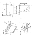
- a masonry block 10 is illustrated in Figures 1-3 .
- the block 10 comprises a block body having a front face 12, a rear face 14, an upper face 16, a lower face 18, and opposed side faces 20, 22.
- the block 10 is formed from a cured, dry cast, no slump masonry concrete. Dry cast, no slump masonry concrete is well known in the art of retaining wall blocks.
- the front face 12 as shown in Figures 1-3 , is provided with a pre-determined three-dimensional pattern.
- the pattern on the front face 12 is preferably imparted to the front face during molding of the block 10 by the action of a moveable stripper shoe (to be later described) having a pattern that is the mirror image of the front face of the block.
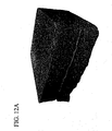
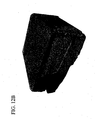
- Figures 12A-C are photos of blocks according to the present invention having patterned front faces.
- the pattern that is imparted to the front face 12 can vary depending upon the desired appearance of the front face.
- the pattern simulates natural stone so that the front face 12 appears to be a natural material, rather than a man-made material.
- the particular stone pattern that is used will be selected based on what is thought to be visually pleasing to users of the blocks.
- the face of the block can be impressed with a pattern that appears to be a single stone, such a river rock.
- the block can be impressed with a pattern that appears to be multiple river rocks in a mortared together pattern.
- the block can be impressed with a pattern that simulates a single piece of quarry rubble, or multiple pieces of field stone, stacked in layers. Endless possibilities are available.
- the resulting patterns on the blocks can be varied by changing stripper shoes.
- the resulting detail and relief that can be provided on the front face is greater than that which can be provided on a front face of a block that results from conventional splitting techniques, and the tumbling, hammermilling and other distressing techniques previously described.
- the relief on the patterned front face 12, measured from the lowest point to the highest point, is preferably at least 0.5 inches (12,7 mm), and more preferably at least 1.0 inches (25,4 mm).
- the front face 12 lies generally in approximately a single plane between the side faces 20, 22, as opposed to the common, three-faceted and curved faces that are frequently seen in split-face retaining wall blocks, although such multi-faceted and curved faces can be easily produced with the present invention.
- the front face 12 is provided with a slight rearward slant, i.e. inclined at an angle ⁇ from the bottom lower face 18 to the upper face 16.
- ⁇ is about 10 degrees.
- front and rear faces 12, 14 are separated by a distance d 1 adjacent the lower face 18 and by a distance d 2 adjacent the upper face 16, with d 1 being larger than d 2 .
- d 1 is about 7.625 inches (193,675 mm) and d 2 is about 6.875 inches (174,625 mm).
- the width d 3 is preferably about 12.0 inches (304,8 mm). It is also contemplated that the front face 12 between the side faces 20, 22 can be faceted, curved, or combinations thereof. In these embodiments, the front face would also have a slight rearward slant.
- the front face 12 also includes radiused edges 24a, 24b at its junctures with the side faces.
- the radiused edges 24a, 24b are formed by arcuate flanges provided on the stripper shoe.
- the radius of the edges 24a, 24b is preferably about 0.25 inches (6,35 mm).
- the radiused edges 24a, 24b shift the contact points between the sides of the block 10 with adjacent blocks in the same course, when a plurality of blocks are laid side-by-side, away from the front face 12, and result in better contact between the blocks to prevent soil "leakage" between adjacent blocks.
- top and bottom edges at the junctures between the front face 12 and the upper and lower faces 16, 18 could also be radiused, similar to the radiused edges 24a, 24b, by the provision of arcuate flanges on the stripper shoe.
- the rear face 14 of the block 10 is illustrated as being generally planar between the side faces 20, 22 and generally perpendicular to the upper and lower faces 16, 18.
- the rear face 14 could deviate from planar, such as by being provided with one or more notches or provided with one or more concavities, while still being within the scope of the invention.
- the width d 4 of the rear face 14 is preferably about 8.202 inches (208, 331 mm).
- the upper face 16 is illustrated in Figures 1-3 as being generally planar, and free of cores intersecting the upper face 16.
- the upper face 16 of each block is in a generally parallel relationship to the upper faces 16 of the other blocks.
- the lower face 18 of the block 10 is formed so as to be suitable for engaging the upper face 16 of the block(s) in the course below to maintain the generally parallel relationship between the upper faces of the blocks 10 when the blocks are stacked into courses.
- the lower face 18 is generally planar and horizontal so that it is generally parallel to the upper face 16.
- other lower faces can be used, including a lower face that includes one or more concave portions or one or more channels over portions of the lower face 18.
- the distance d 6 between the upper face 16 and the lower face 18 is preferably about 4.0 inches (101,6 mm).
- the side faces 20, 22 are generally vertical and join the upper and lower faces 16, 18 and join the front and rear faces 12, 14, as seen in Figures 1-3 . At least a portion of each side face 20, 22 converges toward the opposite side face as the side faces extend toward the rear face 14. Preferably the entire length of each side face 20, 22 converges starting from adjacent the front face 18, with the side faces 20, 22 being generally planar between the front and rear faces 12, 14. However, it is possible that the side faces 20, 22 could start converging from a location spaced from the front face 12, in which case the side faces 20, 22 would comprise a combination of straight, non-converging sections extending from the front face and converging sections leading from the straight sections to the rear face 14. The converging portion of each side face 20,22 preferably converges at an angle ⁇ of about 14.5 degrees.
- the block 10 can be provided with only one converging side face or side face portion, with the other side face being substantially perpendicular to the front and rear faces 12, 14.
- a block with at least one converging side face permits serpentine retaining walls to be constructed.
- the block 10 also preferably includes a flange 26 that extends below the lower face 18 of the block, as seen in Figures 1-3 .
- the flange 26 is designed to abut against the rear face of a block in the course below the block 10 to provide a pre-determined set-back from the course below and provide course-to-course shear strength.
- the flange 26 includes a front surface 28 that engages the rear face of the block(s) in the course below.
- the flange 26 also includes a bottom surface 30, a front, bottom edge 32 between the front surface 28 and the bottom surface 30 that is arcuate, and a rear surface 34 that is extension of, and forms a portion of, the rear face 14 of the block.
- the front surface 28 is preferably angled at an angle ⁇ of about 18 degrees.
- the angled front surface 28 and the arcuate edge 32 result from corresponding shaped portions of the mold, which construction facilitates filling of the mold with dry cast masonry concrete and release of the flange 26 from the mold.
- the flange 26 extends the entire distance between the side faces 20, 22.
- the flange need not extend the entire distance.
- the flange could extend only a portion of the distance between the side faces, and be spaced from the side faces.
- two or more flange portions separated from each other by a gap could be used.
- the depth d 7 of the flange 26 is preferably about 0.750 inches (19.05 mm). This depth defines the resulting set-back of the block relative to the course below. Other flange dimensions could be used, depending upon the amount of desired set-back.
- the rear surface 34 preferably has a height d 8 of about 0.375 inches (9.525 mm).
- the concepts described can also be applied to masonry blocks that are used in the construction of building walls, as well as to concrete bricks, slabs and pavers. In these cases, it is contemplated that neither side face of the block or brick would converge, and that the flange would not be present. However, the patterned front face would provide the block or brick a decorative appearance.
- the masonry block 10 may be used to build any number of landscape structures.
- An example of a structure that may be constructed with blocks is illustrated in Figure 4 .
- a retaining wall 40 composed of individual courses 42a-c of blocks can be constructed.
- the blocks used in constructing the wall 40 can comprise blocks having identically patterned front faces, or a mixture of blocks with different, but compatibly-patterned faces.
- the height of the wall 40 will depend upon the number of courses that are used.
- the construction of retaining walls is well known in the art. A description of a suitable process for constructing the wall 40 is disclosed in U.S. Patent 5,827,015 .
- the flange 26 on the block 10 provides set-back of the block from the course below.
- the course 42b is set-back from the course 42a
- the course 42c is set-back from the course 42b.
- the rearward incline of the front face 12 reduces the ledge that is formed between each adjacent course, by reducing the amount of the upper face portion of each block in the lower course that is visible between the front face of each block in the lower course and the front face of each block in the adjacent upper course.
- the retaining wall 40 illustrated in Figure 4 is straight. However, the preferred block 10 construction with the angled side faces 20, 22 permits the construction of serpentine or curved retaining walls, such as that disclosed in U.S. Patent 5,827,015 .
- An additional aspect concerns the process for forming the block 10.
- the process is initiated by mixing the dry cast masonry concrete that will form the block 10.
- Dry cast, no slump masonry concrete is well known in the art of retaining wall blocks.
- the concrete will be chosen so as to satisfy pre-determined strength, water absorption, density, shrinkage, and related criteria for the block so that the block will perform adequately for its intended use.
- a person having ordinary skill in the art would be able to readily select a material constituency that satisfies the desired block criteria.
- the procedures and equipment for mixing the constituents of the dry cast masonry concrete are well known in the art.
- the mold assembly 50 includes at least one block-forming cavity 56 suitable for forming the preferred block.
- the cavity 56 is open at its top and bottom.
- a pallet is positioned beneath the mold so as to close the bottom of the cavity 56.
- the appropriate amount of dry cast concrete from the hopper is then loaded, via one or more feed drawers, into the block-forming cavity through the open top of the cavity 56.
- the process and equipment for transporting dry cast masonry concrete and loading a block-fomiing cavity are well known in the art.
- the dry cast masonry concrete in the cavity 56 must next be compacted to densify it. This is accomplished primarily through vibration of the dry cast masonry concrete, in combination with the application of pressure exerted on the mass of dry cast masonry concrete from above.
- the vibration can be exerted by vibration of the pallet underlying the mold (table vibration), or by vibration of the mold box (mold vibration), or by a combination of both actions.
- the pressure is exerted by a compression head, discussed below, that carries one or more stripper shoes that contact the mass of dry cast masonry concrete from above.
- the timing and sequencing of the vibration and compression is variable, and depends upon the characteristics of the dry cast masonry concrete used and the desired results.
- a stripper shoe 94 that is brought down into contact with the top of the dry cast masonry concrete in the cavity 56 to compact the concrete.
- the stripper shoe 94 acts with the vibration to compact the concrete within the cavity 56 to form a solid, contiguous, pre-cured block.
- the stripper shoe also includes a three-dimensional pattern 96 on its face for producing a corresponding pattern on the resulting pre-cured block as the stripper shoe compacts the concrete.
- the portion of the pre-cured block contacted by the patterned shoe face comprises the front face of the block.
- the pre-cured block is discharged from the cavity.
- discharge occurs by lowering the pallet 82 relative to the mold assembly, while further lowering the stripper shoe 94 through the mold cavity to assist in stripping the pre-cured block from the cavity.
- the stripper shoe is then raised upwardly out of the mold cavity and the mold is ready to repeat this production cycle.
- mold side walls must be provided in the mold.
- Such mold side walls must be adapted to move into a first position to permit filling of the mold, and compaction and densification of the dry cast masonry concrete, and must be adapted to move into a second position to permit stripping of the mold without damage to the pre-cured block.
- the block may be cured through any means known to those of skill in the art. Examples of curing processes that are suitable for practicing the invention include air curing, autoclaving, and steam curing. Any of these processes for curing the block may be implemented by those of skill in the art.
- the blocks can be packaged for storage and subsequent shipment to a jobsite, and can then be used with other cured blocks in forming a structure, such as the retaining wall 40 in Figure 5 .
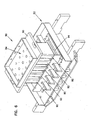
- the mold assembly 50 is illustrated in Figures 6-10 .
- the mold assembly 50 is made from materials that are able to withstand the pressure that is applied during formation of the pre-cured block, as well as provide sufficient wear life.
- the mold assembly 50 is constructed so that the pre-cured block is formed with its front face facing upward, and with its rear face supported on the pallet 82 positioned underneath the mold assembly 50. This permits pattern impressing or other direct processing to occur on the front face 12 of the block, to allow the formation of pre-detemlined block front faces.
- Pre-detemined front faces can include front faces having pre-determined patterns and textures, front faces having pre-determined shapes, front faces made from different material(s) than the remainder of the block, and combinations thereof.
- the mold assembly 50 is designed so that a pre-cured block, including a block with a lower lip or flange and/or one or more converging side faces, can be discharged through the bottom of the mold assembly.
- the mold assembly 50 comprises a mold 52 and a compression head assembly 54 that interacts with the mold 52 as described below.
- the mold 52 comprises at least one block-forming cavity 56 defined therein.
- the mold 52 is sized for use in a standard, "three-at-a-time" American block machine, having a standard pallet size of approximately 18.5 inches (469.9 mm) by 26.0 inches (660.4 mm), which is sized for making three blocks with their upper faces on the pallet.
- the mold 52 comprises a plurality of generally identical block-forming cavities 56.
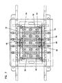
- Figure 7 illustrates five block-forming cavities 56 arranged side-by-side, which is possible when making the preferred size blocks on a standard "three-at-a-time" pallet.
- the cavities 56 are formed by division plates 58, including a pair of outside division plates, a plurality of inside division plates, and a pair of end liners 60 that are common to each cavity 56.
- the use of outside and inside division plates and end liners to form a block-forming cavity in a mold is known to those of skill in the art.
- the division plates and end liners form the boundaries of the block cavities and provide the surfaces that are in contact with the pre-cured blocks during block formation, and are thus susceptible to wear.
- the division plates and end liners are typically removably mounted within the mold 52 so that they can be replaced as they wear or if they become damaged.
- the techniques for mounting division plates and end liners in a mold to form block cavities, and to permit removal of the division plates and end liners, are known to those of skill in the art.
- the division plates 58 form the upper and lower faces 16, 18 of the blocks 10, while the end liners 60 form the side faces 20, 22.
- the division plates and end liners will hereinafter be referred to collectively as the side walls of the cavities.
- side walls refers to division plates and end liners, as well as to any other similar structure that is used to define the boundaries of a block-forming cavity.
- the cavity 56 defined by the side walls 58, 60 has an open top 64 and an open bottom 66.
- the top ends of the side walls 60 e.g. the end liners
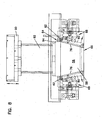
- suitable surrounding structure of the mold 52 to allow the side walls 60 to pivot between the closed position shown in Figure 8 , where the side walls 60 converge toward each other, to a retracted position where the side walls 60 are generally vertical and parallel to each other (not shown).
- the bottom of the cavity 56 is at least as wide as the top of the mold cavity, which allows the pre-cured block to be discharged through the open bottom.
- Pivoting of the side walls 60 is required in order to form the preferred block 10.
- the block 10 is formed "face-up" in the mold 52 with its converging side faces formed by the side walls 60.
- the converging side walls 60 when they are angled as illustrated in Figure 8 , shape the converging side faces 20, 22 of the pre-cured block.
- the front portion of the pre-cured block is wider than the rear portion of the block.
- the side walls 60 In order to be able to discharge the pre-cured block through the open bottom 66, the side walls 60 must pivot outward to enable downward movement of the pre-cured block through the open bottom.
- Biasing mechanisms 68 are provided to maintain the side walls 60 at the converging position during introduction of the concrete and subsequent compacting of the dry cast masonry concrete, and which allow the side walls 60 to pivot to a vertical position during discharge of the pre-cured block.
- a single biasing mechanism 68 is connected to each side wall 60 that is common to all cavities 56, so that the movement of each side wall 60 is controlled via a common mechanism (see Figure 7 ).
- the biasing mechanisms 68 are illustrated as comprising air bags, which will be controlled through the use of air or similar gas. Suitable inlet and outlet ports for the air will be provided, as will a source of high pressure air.
- the use of biasing mechanisms other than air bags is also possible. For example, hydraulic or pneumatic cylinders could be used.
- the air bags When pressurized with air, the air bags will force the side walls 60 to the position shown in Figure 8 .
- the pressurized air is vented from the air bags, which allows the side walls 60 to pivot outward under force of the pre-cured block as the pre-cured block is discharged through the open bottom when the pallet is lowered.
- the side walls 60 remain in contact with the side faces of the pre-cured block.
- biasing mechanisms such as coil springs, can be connected to the side walls 60 to force the side walls to the retracted position when the air bags are vented.
- the side walls 60 will be forced to the retracted position, and the side walls 60 will not contact the side faces of the block during discharge. After discharge, the side walls 60 are returned to the closed, angled position by re-pressurizing the air bags.
- the side walls 60 could be mounted so as to slide inwards to the position shown in Figure 8 and outwards to a position where the bottom of the cavity 56 is at least as wide as the top of the mold cavity.
- the sliding movements could be implemented using a track system in which the side walls are mounted.
- each side wall 60 includes a shaping surface 76 that faces the cavity 56.
- the shaping surfaces 76 are substantially planar. The result is the formation of substantially planar side faces 20, 22 of the block 10.
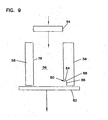
- the side walls 58 that form the upper and lower faces 16, 18 of the block 10 are illustrated.
- the side walls 58 which are fixed and not moveable during the molding process, are substantially vertical.
- the side wall 58 that forms the upper face 16 (the left side wall 58 in Figure 9 ) includes a shaping surface 78 that faces the cavity 56.
- the surface 78 is substantially planar, which results in the formation of a substantially planar upper face 16.
- the side wall 58 that forms the lower face 18 (the right side wall 58 in Figure 9 ) includes an undercut, or "instep”, portion 80 at the bottom edge thereof adjacent the open bottom 66.
- the undercut portion 80 in combination with the pallet 82 that is introduced under the mold 52 to temporarily close the open mold bottom 66 during the molding process, defines a flange-forming subcavity of the cavity 56.
- the flange-forming subcavity has a shape that results in the formation of the flange 26 on the block 10.
- the undercut portion 80 includes a shaping surface 84 that forms the front surface 28 of the flange 26, a shaping surface 86 that forms the bottom surface 30 of the flange, and a shaping surface 88 that forms the edge 32 of the flange 26.
- the portion of the flange 26 that is an extension of the rear face 14 is formed by and on the pallet 82, along with the remainder of the rear face 14.
- the shape of the surfaces 84 and 86 facilitate filling of the undercut portion 80 with the concrete during introduction and subsequent compacting of the concrete so that the flange 26 is completely formed, as well as aid in release of the flange 26 from the surfaces 84, 86 during block discharge.
- the side walls 60 would be oriented vertically instead of being converging. Further, in the case of a block without a flange on the lower face and with converging side faces, the undercut 80 would not be present. In the case of a block without a flange on the lower face and without converging side faces, the undercut 80 would not be present and the side walls 60 would be oriented vertically.
- the head assembly 54 is seen to include a compression head 90 in the form of a plate.
- the head 90 is actuated by an actuating mechanism in a manner known in the art so that the head 90 is moveable vertically up and down to bring about compaction of the dry cast masonry concrete in the mold cavities 56 and to assist in stripping the pre-cured blocks from the mold 52.
- each stand-off 92 Connected to and extending from the bottom of the head 90 are a plurality of stand-offs 92, one stand-off for each block-forming cavity 56 as shown in Figure 6 .
- the stand-offs 92 are spaced from each other, with the longitudinal axis of each stand-off oriented perpendicular to the plane of the head 90 and extending generally centrally through the block-forming cavity 56.
- a stripper shoe 94 illustrated in Figures 6 , 8 , 9 and 10 , is connected to the end of each stand-off 92.
- the stripper shoe 94 is rectangular in shape and is dimensioned so that it may enter the respective cavity 56 through the open top to contact the concrete to compact the concrete, and to travel through the cavity during discharge of the pre-cured block.
- the dimensions of the stripper shoe 94 are only slightly less than the dimensions of the open top 64 of the cavity 56, so that the shoe 94 fits into the cavity 56 with little or no spacing between the sides of the shoe 94 and the side walls 58, 60 defining the cavity. This minimizes escape of concrete between the sides of the shoe 94 and the side walls 58, 60 during compression, and maximizes the front face area of the block that is contacted by the shoe 94.
- Flanges 98a, 98b are formed on opposite ends of the face of the stripper shoe 94, as best seen in Figure 10 .
- the flanges 98a, 98b are arcuate to produce the rounded edges 24a, 24b on front face 12 of the block. If desired, arcuate flanges can be provided on the two remaining ends of the stripper shoe 94, in order to produce upper and lower rounded edges on the front face 12.
- a face of the shoe 94 is provided with a pre-determined pattern 96 so that, as the shoe 94 compacts the concrete, the pattern is imparted to the front face of the block.
- the pattern 96 simulates natural stone, so that the front face of the resulting block simulates natural stone thereby making the block appear more natural and "rock-like".
- a variety of different patterns 96 can be provided on the shoe 94, depending upon the appearance of the front face that one wishes to achieve.
- the face of the shoe 94 can be shaped to achieve a faceted or curved block front face. Indeed, the face of the shoe 94 can be patterned and/or shaped in any manner which one desires in order to achieve a desired appearance of the block front face.
- Figure 10 provides an example of a pre-determined pattern 96 that can be provided on the shoe 94.
- the pattern 96 simulates natural stone.
- the pattern 96 is preferably machined into the shoe face based upon a pre-determined three-dimensional pattern.
- An exemplary process for creating the pre-determined pattern 96 on the shoe face is as follows.
- one or more natural rocks having surfaces which one considers to be visually pleasing are selected.
- One or more of the rock surfaces are then scanned using a digital scanning machine.
- An example of a suitable scanning machine for practicing the invention is the Laser Design Surveyor 1200 having an RPS 150 head, available from Laser Design Incorporated of Minneapolis, Minnesota.
- the Laser Design Surveyor 1200 has a linear accuracy of 0.0005" (0.0127 mm) in the XYZ coordinates, and a resolution of 0.0001 " (0,00254 mm).
- the scan data for the rock surfaces is collected and manipulated to blend the scan data for each scanned surface together to create a seamless data blend of the various rock surfaces.
- the software for collecting and manipulating the scan data is known in the art, for example, DataSculpt available from Laser Design Incorporated of Minneapolis, Minnesota.
- the data blend is then scaled and/or trimmed to the dimension of the block front face.
- the scaled data blend represents a single rock surface blended from the individually scanned rock surfaces.
- the scaled blend data is then output to a three or four axis, numerically controlled milling machine for milling of the stripper shoe 94.
- a suitable milling machine for practicing the invention is the Mikron VCP600 available from Mikron AG Nidau ofNidau, Switzerland.
- the milling machine mills a mirror image of the rock surface, represented by the scaled data blend, into the face of the stripper shoe 94, which is suitably mounted in the milling machine in known fashion.
- the result is a pre-determined pattern milled into the face of the shoe 94, which, in turn, results in a pre-determined pattern impressed into the front face of the block when the shoe 94 compacts the concrete.
- This process can be repeated to produce additional shoes having the same or different face patterns. This is advantageous because the patterned face of each shoe is subject to wear, and the shoe will need to be replaced when the pattern becomes excessively worn. Further, by forming a variety of different pre-determined shoe patterns, a variety of different block front face appearances can be achieved. Other shoe patterns can be formed by combining the scanned surfaces of a plurality of different rocks.
- the resulting detail and relief that is provided on the block front face can be significantly greater than the detail and relief that is provided on the front face of a block that results from conventional splitting techniques, and the other front face distressing techniques discussed above.
- the scan data can be manipulated in order to increase or decrease the relief that is milled into the shoe face, which will alter the relief that is ultimately provided on the block front face.
- Heating mold components to prevent sticking of dry cast masonry concrete is known in the art.
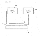
- a heater 100 is connected to the shoe 94 for heating the shoe.
- the heater 100 is controlled by a temperature control unit 102.
- a thermocouple 104 mounted on the shoe 94 senses the temperature of the shoe, and relays that information to a power control unit 106 that provides electrical power to the control unit 102 and the heater 100.
- the system is designed such that, when the temperature of the shoe 94 falls below a pre-determined level as sensed by the thermocouple 104, power is provided to the heater 100 to increase the shoe temperature.
- the heater 100 is shut off.
- the shoe temperature can be maintained as selected levels.
- control unit 102 is designed to allow selection of the minimum and maximum temperature levels, based on the dry cast masonry concrete that is being used.
- the surface temperature of the stripper shoe 94 is maintained between 120 °F and 130 °F (48.9°C and 54.4°C).
Landscapes
- Engineering & Computer Science (AREA)
- Architecture (AREA)
- Ceramic Engineering (AREA)
- Mechanical Engineering (AREA)
- Manufacturing & Machinery (AREA)
- Chemical & Material Sciences (AREA)
- Civil Engineering (AREA)
- Structural Engineering (AREA)
- Life Sciences & Earth Sciences (AREA)
- Wood Science & Technology (AREA)
- Moulds, Cores, Or Mandrels (AREA)
- Retaining Walls (AREA)
- Press-Shaping Or Shaping Using Conveyers (AREA)
- Secondary Cells (AREA)
- Devices For Post-Treatments, Processing, Supply, Discharge, And Other Processes (AREA)
- Revetment (AREA)
Claims (7)
- Procédé de production d'un patin de démoulage, le patin de démoulage étant utilisé dans un processus de production d'un bloc de béton coulé à sec avec un motif tridimensionnel imprimé dans une face avant du bloc ;
dans lequel le procédé comprend :de pourvoir le patin de démoulage de l'image en miroir du motif tridimensionnel prédéterminé qui simule une pierre naturelle sur lui en :1) fournissant un motif pour mettre sur le patin de démoulage en sélectionnant une ou plusieurs surfaces de roche naturelle ;2) scannant les surfaces des une ou plusieurs surfaces de roche naturelle en utilisant un appareil de scannage numérique pour former des données scannées, le scannage fournissant les données scannées ayant des données d'axes X, Y et Z ;3) collectant et manipulant les données scannées pour augmenter ou diminuer le relief à meuler dans la face du patin de démoulage ; l'étape de manipulation des données scannées incluant aussi la manipulation des données scannées pour créer des angles de dépouille appropriés pour libérer le béton coulé à sec du patin de démoulage ;4) mettant à l'échelle et/ou réduisant les données collectées et manipulées aux dimensions de la surface avant du bloc pour former des données mises à l'échelle et/ou réduites, les données mises à l'échelle et/ou réduites représentant une surface de roche simple à partir des une ou plusieurs surfaces de roche naturelle scannées individuellement ;5) meuler l'image en miroir des données mises à l'échelle et/ou réduites dans la face du patin de démoulage pour produire dessus l'image en miroir du motif tridimensionnel pré-dimensionné qui simule une pierre naturelle; le motif ayant un relief maximum d'au moins environ 12,7 mm (environ 0,5 pouces). - Procédé selon la revendication 1, dans lequel
l'étape consistant à fournir un motif pour mettre sur le patin de démoulage comprend de sélectionner deux ou plus surfaces de roche naturelle ;
l'étape de scannage comprend de scanner les deux ou plus surfaces de roche naturelle en utilisant un appareil de scannage numérique pour former des données scannées ; et
l'étape consistant à collecter et manipulant les données scannées inclut de manipuler les données scannées pour mélanger les données scannées de chaque surface scannée pour créer un mélange de données ininterrompu. - Procédé selon la revendication 1, comprenant de former un rebord entourant le périmètre de la face du patin de démoulage.
- Procédé selon la revendication 1, incluant :de fournir un moule ayant une pluralité de parois latérales définissant une cavité de moule, le moule incluant le patin de démoulage avec le motif tridimensionnel prédéterminé dessus ;de positionner une palette sous la cavité de moule pour fermer temporairement le fond ouvert de la cavité de moule ;d'introduire du béton coulé à sec dans la cavité de moule ;de compacter le béton coulé à sec pour former un bloc de béton pré-durci, dans lequel pendant le compactage, le motif tridimensionnel du patin de démoulage est imprimé dans la face du bloc de béton pré-durci par le patin de démoulage ;de décharger le bloc de béton pré-durci de la cavité de moule ; etde faire durcir le bloc de béton pré-durci.
- Procédé selon la revendication 4, dans lequel l'étape de compactage du béton coulé à sec inclut de presser la face du patin de démoulage dans le béton coulé à sec contenu dans la cavité de moule.
- Procédé selon la revendication 4, dans lequel le bloc de béton comprend un bloc de paroi de retenue segmentaire ayant des faces supérieure et inférieure, la face avant, une face arrière, et des faces latérales opposées, dans lequel la cavité de moule comprend un haut ouvert et un bas ouvert.
- Procédé selon la revendication 6, dans lequel le moule inclut une pluralité de cavités de moule qui fonctionnent avec la palette pour mouler une pluralité de blocs en même temps.
Priority Applications (1)
| Application Number | Priority Date | Filing Date | Title |
|---|---|---|---|
| EP12192880A EP2559824A1 (fr) | 2002-01-04 | 2002-12-27 | Procédé et moule pour la fabrication d'un bloc de maçonnerie en béton |
Applications Claiming Priority (2)
| Application Number | Priority Date | Filing Date | Title |
|---|---|---|---|
| US10/038,639 US7140867B2 (en) | 2002-01-04 | 2002-01-04 | Mold for making a masonry block |
| EP02796089A EP1466058B1 (fr) | 2002-01-04 | 2002-12-27 | Procédé et assemblage de moule pour la fabrication d'un bloc en béton |
Related Parent Applications (2)
| Application Number | Title | Priority Date | Filing Date |
|---|---|---|---|
| EP02796089A Division EP1466058B1 (fr) | 2002-01-04 | 2002-12-27 | Procédé et assemblage de moule pour la fabrication d'un bloc en béton |
| EP02796089.7 Division | 2002-12-27 |
Related Child Applications (1)
| Application Number | Title | Priority Date | Filing Date |
|---|---|---|---|
| EP12192880A Division-Into EP2559824A1 (fr) | 2002-01-04 | 2002-12-27 | Procédé et moule pour la fabrication d'un bloc de maçonnerie en béton |
Publications (3)
| Publication Number | Publication Date |
|---|---|
| EP2095923A2 EP2095923A2 (fr) | 2009-09-02 |
| EP2095923A3 EP2095923A3 (fr) | 2011-02-02 |
| EP2095923B1 true EP2095923B1 (fr) | 2015-09-02 |
Family
ID=21901054
Family Applications (3)
| Application Number | Title | Priority Date | Filing Date |
|---|---|---|---|
| EP09007521.9A Expired - Lifetime EP2095923B1 (fr) | 2002-01-04 | 2002-12-27 | procédé de fabrication d'une plaque d'éjection |
| EP12192880A Withdrawn EP2559824A1 (fr) | 2002-01-04 | 2002-12-27 | Procédé et moule pour la fabrication d'un bloc de maçonnerie en béton |
| EP02796089A Expired - Lifetime EP1466058B1 (fr) | 2002-01-04 | 2002-12-27 | Procédé et assemblage de moule pour la fabrication d'un bloc en béton |
Family Applications After (2)
| Application Number | Title | Priority Date | Filing Date |
|---|---|---|---|
| EP12192880A Withdrawn EP2559824A1 (fr) | 2002-01-04 | 2002-12-27 | Procédé et moule pour la fabrication d'un bloc de maçonnerie en béton |
| EP02796089A Expired - Lifetime EP1466058B1 (fr) | 2002-01-04 | 2002-12-27 | Procédé et assemblage de moule pour la fabrication d'un bloc en béton |
Country Status (15)
| Country | Link |
|---|---|
| US (3) | US7140867B2 (fr) |
| EP (3) | EP2095923B1 (fr) |
| JP (2) | JP4313679B2 (fr) |
| KR (1) | KR100921853B1 (fr) |
| CN (1) | CN100359113C (fr) |
| AT (1) | ATE518997T1 (fr) |
| AU (2) | AU2002360807B2 (fr) |
| CA (2) | CA2720482A1 (fr) |
| DK (1) | DK1466058T3 (fr) |
| ES (1) | ES2368324T3 (fr) |
| MX (1) | MXPA04006525A (fr) |
| NO (1) | NO336251B1 (fr) |
| NZ (3) | NZ541835A (fr) |
| PT (1) | PT1466058E (fr) |
| WO (1) | WO2003060251A1 (fr) |
Families Citing this family (140)
| Publication number | Priority date | Publication date | Assignee | Title |
|---|---|---|---|---|
| US5294216A (en) | 1989-09-28 | 1994-03-15 | Anchor Wall Systems, Inc. | Composite masonry block |
| US7140867B2 (en) * | 2002-01-04 | 2006-11-28 | Anchor Wall Systems, Inc. | Mold for making a masonry block |
| US7208112B2 (en) * | 2002-01-04 | 2007-04-24 | Anchor Wall Systems, Inc. | Concrete block and method of making same |
| US6874494B2 (en) * | 2002-03-20 | 2005-04-05 | Anchor Wall Systems, Inc. | Block splitting assembly and method |
| CA2387181A1 (fr) * | 2002-05-22 | 2003-11-22 | Les Materiaux De Construction Oldcastle Canada Inc. | Blocs artificiels de maconnerie et necessaire pour former des murs en maconnerie |
| US20040098938A1 (en) * | 2002-11-22 | 2004-05-27 | Anchor Wall Systems, Inc. | Decorated concrete block |
| US20040218985A1 (en) * | 2003-04-30 | 2004-11-04 | Klettenberg Charles N. | Method of making a composite masonry block |
| USD500864S1 (en) | 2003-07-17 | 2005-01-11 | Marshall Concrete Products, Inc. | Ornamental face for retaining wall block |
| USD501935S1 (en) * | 2003-07-21 | 2005-02-15 | Keystone Retaining Wall Systems, Inc. | Wall block |
| US7261548B2 (en) * | 2003-07-29 | 2007-08-28 | Haberman Machine | Concrete block mold with moveable liner |
| US7980842B2 (en) | 2003-07-29 | 2011-07-19 | Ness Inventions, Inc. | Concrete block mold with moveable liner and heater |
| US20050211871A1 (en) * | 2003-07-29 | 2005-09-29 | Ness John T | Interlocking masonry blocks and method and system of making interlocking masonry blocks |
| US20050120670A1 (en) * | 2003-07-29 | 2005-06-09 | Ness John T. | Masonry blocks and method and system of making masonry blocks |
| US8186644B2 (en) * | 2003-07-29 | 2012-05-29 | Ness Inventions, Inc. | Concrete block mold with movable liners with master bar |
| US20050121830A1 (en) * | 2003-07-29 | 2005-06-09 | Ness John T. | Masonry blocks and method and system of making masonry blocks |
| US7156645B2 (en) * | 2003-07-29 | 2007-01-02 | Ness Inventions, Inc. | Concrete block mold with moveable liner |
| US7175414B2 (en) * | 2003-07-29 | 2007-02-13 | Ness Inventions, Inc. | Block mold having moveable liner |
| US8123512B2 (en) | 2003-07-29 | 2012-02-28 | Ness Inventions, Inc. | Concrete block mold with moveable liner |
| USD541950S1 (en) | 2003-11-21 | 2007-05-01 | Anchor Wall Systems, Inc. | Molded surface of a concrete product |
| USD511578S1 (en) | 2003-11-21 | 2005-11-15 | Anchor Wall Systems, Inc. | Molded surface of a concrete product |
| USD518578S1 (en) | 2003-11-21 | 2006-04-04 | Anchor Wall Systems, Inc. | Molded surface of a concrete product |
| US7704435B2 (en) * | 2004-07-30 | 2010-04-27 | Rampf Molds Industries, Inc. | Apparatus and method for utilizing a universal plunger |
| US7500845B2 (en) | 2005-01-13 | 2009-03-10 | Ness Inventions, Inc. | Apparatus and method for forming retaining wall blocks with variable depth flanges |
| US20060191231A1 (en) * | 2005-01-13 | 2006-08-31 | Ness John T | Masonry blocks and method of making masonry blocks having overlapping faces |
| US7743574B2 (en) * | 2005-02-11 | 2010-06-29 | Anchor Wall Systems, Inc. | System of blocks for use in forming a free standing wall |
| US7575700B2 (en) * | 2005-03-01 | 2009-08-18 | Pampf Molds Industries, Inc. | Apparatus and method for a mold alignment system |
| US8101113B2 (en) * | 2005-04-21 | 2012-01-24 | Oldcastle Building Products Canada, Inc. | Molding apparatus for producing dry cast products having textured side surfaces |
| US7470121B2 (en) | 2005-05-10 | 2008-12-30 | Ness Inventions, Inc. | Block mold having moveable liner |
| US7704434B2 (en) * | 2005-06-07 | 2010-04-27 | Anchor Wall Systems, Inc. | Concrete block with beveled core opening edge |
| US7862763B2 (en) * | 2005-06-23 | 2011-01-04 | Anchor Wall Systems, Inc. | Methods of quality control in concrete block production |
| USD529195S1 (en) | 2005-07-01 | 2006-09-26 | Anchor Wall Systems, Inc. | Retaining wall block |
| US20070009628A1 (en) * | 2005-07-11 | 2007-01-11 | Rampf Molds Industries, Inc. | Systems and methods for attaching and aligning a tamperhead in production machinery |
| USD530831S1 (en) | 2005-07-13 | 2006-10-24 | Anchor Wall Systems, Inc. | Retaining wall block |
| US7674420B2 (en) * | 2005-08-03 | 2010-03-09 | Anchor Wall Systems, Inc. | Dimensional control of concrete blocks |
| US20070193181A1 (en) * | 2006-01-30 | 2007-08-23 | Klettenberg Charles N | Dry-cast concrete block |
| US20100006010A1 (en) * | 2006-03-01 | 2010-01-14 | Ihor Hinczak | Matrix for masonry elements and method of manufacture thereof |
| DE102006023485A1 (de) * | 2006-05-18 | 2007-11-22 | Eos Gmbh Electro Optical Systems | Vorrichtung und Verfahren zum Herstellen eines dreidimensionalen Objekts |
| US8844228B2 (en) * | 2006-06-14 | 2014-09-30 | Oldcastle Building Products Canada, Inc. | Dry-cast concrete block |
| TWI278295B (en) * | 2006-07-07 | 2007-04-11 | Ming-Guei Wang | Corner paintbrush |
| US7632036B2 (en) * | 2006-07-25 | 2009-12-15 | Rocvale Produits De Beton Inc. | Notched paving stone unit and paved assemblies fabricated therewith |
| EP1886780A3 (fr) * | 2006-07-28 | 2008-03-12 | Jens Gessner | Outil destiné à la fabrication de blocs en béton |
| DE102006050754A1 (de) * | 2006-10-27 | 2008-04-30 | Metten Stein + Design Gmbh & Co. Kg | Verfahren zur Formgestaltung von Betonsteinen und/oder Betonplatten |
| USD584423S1 (en) | 2006-12-14 | 2009-01-06 | Anchor Wall Systems, Inc. | Molded surface of a concrete product |
| USD588713S1 (en) | 2007-01-19 | 2009-03-17 | Anchor Wall Systems, Inc. | Molded surface of a concrete product |
| US9206599B2 (en) * | 2007-02-02 | 2015-12-08 | Les Materiaux De Construction Oldcastle Canada, Inc. | Wall with decorative facing |
| MX2009008130A (es) * | 2007-02-02 | 2009-10-20 | Materiaux De Construction Oldc | Pared con acabado decorativo. |
| USD598135S1 (en) | 2007-03-14 | 2009-08-11 | Anchor Wall Systems, Inc. | Molded surface of a concrete product |
| US7695268B2 (en) * | 2007-04-19 | 2010-04-13 | Marshall Concrete | System and method for manufacturing concrete blocks |
| USD585567S1 (en) | 2007-05-14 | 2009-01-27 | Anchor Wall Systems, Inc. | Molded surface of a concrete product |
| US8182260B2 (en) * | 2007-06-25 | 2012-05-22 | Rampf Molds Industries, Inc. | Apparatus and method for forming tapered products |
| US20090000234A1 (en) * | 2007-06-26 | 2009-01-01 | Bott Timothy A | Concrete blocks with non-geometric face surfaces |
| USD588714S1 (en) | 2007-08-06 | 2009-03-17 | Anchor Wall Systems, Inc. | Molded surface of a concrete product |
| US20110078978A1 (en) * | 2007-09-12 | 2011-04-07 | Wauhop Billy J | Retaining wall block, method of manufacturing retaining wall block and retaining wall comprised of retaining wall blocks |
| CA2700908C (fr) * | 2007-10-18 | 2016-04-26 | Keystone Retaining Wall Systems, Inc. | Bloc de mur de soutenement |
| MX2010003819A (es) | 2007-11-08 | 2010-04-30 | Keystone Retaining Wall System | Bloque de pared con almohadillas de soporte de peso y metodo de produccion de bloques de pared. |
| US9388571B2 (en) * | 2007-11-21 | 2016-07-12 | Dustin A. Brown | Stone fabrication system with hidden mortar joint |
| US20090191010A1 (en) * | 2008-01-24 | 2009-07-30 | King Samuel L | Retaining wall block and mold |
| USD620614S1 (en) | 2008-03-13 | 2010-07-27 | Anchor Wall Systems, Inc. | Molded surface of a concrete product |
| WO2009117608A1 (fr) | 2008-03-20 | 2009-09-24 | Ness Inventions, Inc. | Système et procédé de fabrication de blocs de maçonnerie |
| US20090255211A1 (en) * | 2008-04-14 | 2009-10-15 | Ryan Collison | Method and means for producing a concrete block |
| USD634028S1 (en) | 2008-04-18 | 2011-03-08 | Anchor Wall Systems, Inc. | Sculpted cap block |
| US7849656B2 (en) | 2008-04-18 | 2010-12-14 | Anchor Wall Systems, Inc. | Dry cast block arrangement and methods |
| USD650094S1 (en) | 2008-04-18 | 2011-12-06 | Anchor Wall Systems, Inc. | Sculpted cap block |
| USD621069S1 (en) | 2008-04-18 | 2010-08-03 | Anchor Wall Systems, Inc. | Sculpted cap block |
| USD600359S1 (en) | 2008-06-04 | 2009-09-15 | King Samuel L | Retaining wall block |
| US8522694B2 (en) | 2008-06-20 | 2013-09-03 | Oria Collapsibles, Llc | Structural supporting pallet construction with improved perimeter impact absorbing capabilities |
| US8167605B2 (en) * | 2008-06-20 | 2012-05-01 | Oria Collapsibles, Llc | Production assembly and process for mass manufacture of a thermoplastic pallet incorporating a stiffened insert |
| US8438981B2 (en) | 2008-06-20 | 2013-05-14 | Oria Collapsibles, Llc | Pallet design with buoyant characteristics |
| US8701569B2 (en) | 2008-06-20 | 2014-04-22 | Oria Collapsibles, Llc | Pallet design with structural reinforcement |
| USD589161S1 (en) * | 2008-07-10 | 2009-03-24 | Rosetta Hardscapes Llc | Concrete block simulating natural stone |
| USD589159S1 (en) * | 2008-07-10 | 2009-03-24 | Rosetta Hardscapes, Llc | Concrete block simulating natural stone |
| USD589163S1 (en) * | 2008-07-10 | 2009-03-24 | Rosetta Hardscapes, Llc | Concrete block simulating natural stone |
| USD589162S1 (en) * | 2008-07-10 | 2009-03-24 | Rosetta Hardscapes, Llc | Concrete block simulating natural stone |
| USD589160S1 (en) * | 2008-07-10 | 2009-03-24 | Rosetta Hardscapes Llc | Concrete block simulating natural stone |
| USD589167S1 (en) * | 2008-07-11 | 2009-03-24 | Rosetta Hardscapes, Llc | Concrete block simulating natural stone |
| USD589168S1 (en) * | 2008-07-11 | 2009-03-24 | Rosetta Hardscapes, Llc | Concrete block simulating natural stone |
| USD589166S1 (en) * | 2008-07-11 | 2009-03-24 | Rosetta Hardscapes, Llc | Concrete block simulating natural stone |
| USD589164S1 (en) * | 2008-07-11 | 2009-03-24 | Rosetta Hardscapes, Llc | Concrete block simulating natural stone |
| USD589631S1 (en) * | 2008-07-11 | 2009-03-31 | Rosetta Handscapes, Llc | Concrete block simulating natural stone |
| USD589165S1 (en) * | 2008-07-11 | 2009-03-24 | Rosetta Hardscapes, Llc | Concrete block simulating natural stone |
| USD589169S1 (en) * | 2008-07-11 | 2009-03-24 | Rosetta Hardscapes, Llc | Concrete block simulating natural stone |
| US7757451B2 (en) * | 2008-11-18 | 2010-07-20 | Lee Lum Mark E | Ventilated building block |
| USD619733S1 (en) | 2008-11-18 | 2010-07-13 | Anchor Wall Systems, Inc. | Molded surfaces of a concrete product |
| USD619732S1 (en) | 2008-11-18 | 2010-07-13 | Anchor Wall Systems, Inc. | Molded surface of a concrete product |
| USD619734S1 (en) | 2008-12-19 | 2010-07-13 | Anchor Wall Systems, Inc. | Molded surface of a concrete product |
| US7908799B2 (en) | 2009-01-30 | 2011-03-22 | Anchor Wall Systems, Inc. | Wall blocks, wall block kits, walls resulting therefrom, and methods |
| US7972128B2 (en) * | 2009-02-23 | 2011-07-05 | Anchor Wall Systems, Inc. | Mold and process for forming concrete retaining wall blocks |
| USD620133S1 (en) | 2009-02-25 | 2010-07-20 | Anchor Wall Systems, Inc. | Molded surface of a concrete product |
| US7967595B1 (en) | 2009-04-02 | 2011-06-28 | John Paul Schofield | Machine and method for reshaping multiple plastic bottles into rock shapes |
| USD620134S1 (en) | 2009-05-19 | 2010-07-20 | Anchor Wall Systems, Inc. | Molded surface of a concrete product |
| CA2764506A1 (fr) | 2009-06-05 | 2010-12-09 | Ness Inventions, Inc. | Moule a blocs dote d'un revetement mobile |
| WO2010141941A1 (fr) | 2009-06-05 | 2010-12-09 | Ness Inventions, Inc. | Assemblage de moule employant un chauffage par fluide |
| US20110059199A1 (en) * | 2009-09-04 | 2011-03-10 | Horacio Correia | Mold for blocks wih movable cavity walls |
| GB0919626D0 (en) * | 2009-11-10 | 2009-12-23 | Gray John E | Building block and production thereof |
| USD636093S1 (en) | 2010-03-02 | 2011-04-12 | Anchor Wall Systems, Inc. | Molded surface of a concrete product |
| DE102010023936A1 (de) * | 2010-06-16 | 2011-12-22 | Rampf Formen Gmbh | Verfahren zur Bereitstellung einer Oberflächenstruktur für Formsteine |
| US9441342B2 (en) | 2010-09-28 | 2016-09-13 | Les Materiaux De Construction Oldcastle Canada, In | Retaining wall |
| EP2622141B1 (fr) | 2010-09-28 | 2023-06-14 | Les Matériaux de Construction Oldcastle Canada, Inc. | Mur de soutènement |
| US9670640B2 (en) | 2010-09-28 | 2017-06-06 | Les Materiaux De Construction Oldcastle Canada, Inc. | Retaining wall |
| USD653772S1 (en) | 2010-11-29 | 2012-02-07 | Anchor Wall Systems, Inc. | Molded surface of a concrete product |
| USD645165S1 (en) | 2010-12-03 | 2011-09-13 | Anchor Wall Systems, Inc. | Molded surface of a concrete product |
| USD678552S1 (en) | 2011-05-05 | 2013-03-19 | Anchor Wall Systems, Inc. | Molded surface of a concrete product |
| USD679833S1 (en) | 2011-05-05 | 2013-04-09 | Anchor Wall Systems, Inc. | Molded surface of a concrete product |
| USD685923S1 (en) | 2011-05-05 | 2013-07-09 | Anchor Wall Systems, Inc. | Molded surface of a concrete product |
| MX2011009247A (es) * | 2011-09-02 | 2013-03-18 | Leonardo Maximino Cortes Martinez | Prensa para la fabricacion de bloques constructivos de ensamble machihembrado. |
| US9145676B2 (en) | 2011-11-09 | 2015-09-29 | E.P. Henry Corporation | Masonry block with taper |
| US8956147B2 (en) | 2011-11-22 | 2015-02-17 | The OHorizons Foundation | Mold for rectangular structure |
| USD703346S1 (en) | 2012-09-12 | 2014-04-22 | Anchor Wall Systems, Inc. | Molded surface of a concrete product |
| USD693481S1 (en) | 2012-11-05 | 2013-11-12 | Anchor Wall Systems, Inc. | Molded surface of a concrete product |
| WO2014127486A1 (fr) | 2013-02-25 | 2014-08-28 | Les Materiaux De Construction Oldcastle Canada Inc. | Ensemble mur |
| EP2961888B1 (fr) | 2013-03-01 | 2017-07-26 | Oldcastle Building Products Canada Inc. | Dalle de pavage conçue pour former un motif arbitraire |
| US20140272284A1 (en) * | 2013-03-15 | 2014-09-18 | David M. Franke | Multi zone cementitious product and method |
| ES2640389T3 (es) | 2013-05-15 | 2017-11-02 | Anchor Wall Systems, Inc. | Bloque de construcción multiuso |
| US9701046B2 (en) | 2013-06-21 | 2017-07-11 | Pavestone, LLC | Method and apparatus for dry cast facing concrete deposition |
| US10583588B2 (en) | 2013-06-21 | 2020-03-10 | Pavestone, LLC | Manufactured retaining wall block with improved false joint |
| USD791346S1 (en) | 2015-10-21 | 2017-07-04 | Pavestone, LLC | Interlocking paver |
| WO2015048403A1 (fr) | 2013-09-26 | 2015-04-02 | Keystone Retaining Wall Systems Llc | Bloc, système de bloc et procédé de fabrication de bloc |
| US9649778B2 (en) * | 2013-12-02 | 2017-05-16 | Angelo Risi | Method and mold for manufacturing an interlocking concrete block |
| US9481105B2 (en) | 2013-12-12 | 2016-11-01 | Watershed Materials, Llc | System, method and apparatus for fabricating environmental masonry units |
| USD737468S1 (en) | 2014-05-07 | 2015-08-25 | Pavestone, LLC | Front face of a retaining wall block |
| USD729414S1 (en) | 2014-05-13 | 2015-05-12 | Anchor Wall Systems, Inc. | Modular building block |
| USD743055S1 (en) | 2014-06-11 | 2015-11-10 | Keystone Retaining Wall Systems Llc | Surface of a landscaping block |
| US9834902B2 (en) | 2015-02-25 | 2017-12-05 | Keystone Retaining Wall Systems Llc | Blocks, block systems and methods of making blocks |
| US10569238B2 (en) | 2015-02-27 | 2020-02-25 | Watershed Materials, Llc | Vertical shaft high-shear mixer for de-agglomeration, and associated methods and systems |
| US10486345B2 (en) | 2015-02-27 | 2019-11-26 | Watershed Materials, Llc | Dynamic block press, and associated methods and systems |
| US20170057872A1 (en) * | 2015-08-31 | 2017-03-02 | Watershed Materials, Llc | Alkali-Activated Natural Aluminosilicate Materials for Compressed Masonry Products, and Associated Processes and Systems |
| US10273683B2 (en) * | 2016-10-17 | 2019-04-30 | Vaughn Fryfogle | Blocks and molds for building landscape walls and methods of making the blocks |
| KR102816485B1 (ko) | 2017-07-24 | 2025-06-05 | 앵커 월 시스템즈 인코퍼레이티드 | 시각적으로 향상된 콘트라스트 표면 섹션을 갖는 몰딩된 콘크리트 블록; 이의 방법 및 사용 |
| US10760269B2 (en) * | 2017-10-25 | 2020-09-01 | Keystone Retaining Wall Systems Llc | Retaining wall block and retaining wall block system |
| USD866799S1 (en) | 2018-03-09 | 2019-11-12 | Keystone Retaining Wall Systems Llc | Landscaping block |
| US10711425B2 (en) | 2018-03-09 | 2020-07-14 | Keystone Retaining Wall Systems Llc | Wall blocks having one or more multi-faceted faces or side walls, wall block systems and methods of constructing a wall |
| CN109435023B (zh) * | 2018-11-29 | 2023-11-21 | 北京市政路桥管理养护集团有限公司 | 用于地面井体结构预制模块的模具及组合使用方法 |
| CN109333776B (zh) * | 2018-12-26 | 2024-07-30 | 陈锐 | 一种瓷砖模具及扩展瓷砖模具支座和该模具压制成的瓷砖 |
| CN112661475B (zh) * | 2020-12-31 | 2022-03-08 | 成都富思特新材料有限公司 | 一种涂饰轻质仿砖材料及仿砖的加工方法 |
| CN114002413A (zh) * | 2021-09-24 | 2022-02-01 | 天津大学 | 一种混凝土防渗墙施工过程智能监控方法 |
| USD1037491S1 (en) | 2021-12-14 | 2024-07-30 | Pavestone, LLC | Wall block |
| CN115122464A (zh) * | 2022-06-27 | 2022-09-30 | 重庆市欧华陶瓷(集团)有限责任公司 | 一种建筑用仿古砖生产设备及其生产工艺 |
| CN115324062A (zh) * | 2022-08-31 | 2022-11-11 | 保利长大工程有限公司 | 用于调节混凝土搅拌物卸料高度的串筒及其使用方法 |
| CN117001808B (zh) * | 2023-08-25 | 2025-07-29 | 中国水利水电第七工程局有限公司 | 一种混凝土立体成型模具 |
| CN117513341B (zh) * | 2023-12-25 | 2026-01-20 | 中冶建工集团有限公司 | 挡墙级配碎石反滤层施工方法 |
Family Cites Families (93)
| Publication number | Priority date | Publication date | Assignee | Title |
|---|---|---|---|---|
| US819055A (en) * | 1906-05-01 | Willis H Fisher | Mold-box. | |
| US415773A (en) * | 1889-11-26 | Brick | ||
| US182011A (en) * | 1876-09-05 | Improvement in ships galleys | ||
| US838278A (en) * | 1904-12-19 | 1906-12-11 | John F Schwartz | Mold. |
| US799754A (en) * | 1905-02-23 | 1905-09-19 | John B Petrie | Pattern-frame for cement-molding machines. |
| US803014A (en) * | 1905-04-11 | 1905-10-31 | David Mcilravy | Machine for producing artificial stone. |
| US813901A (en) * | 1905-05-06 | 1906-02-27 | Parmenos Grant Leming | Molding-machine. |
| US824235A (en) * | 1905-06-26 | 1906-06-26 | Nelson L Damon | Mold for making artificial stone. |
| US1166312A (en) * | 1912-03-19 | 1915-12-28 | William H Barten | Apparatus for making concrete blocks. |
| US1086975A (en) | 1913-02-20 | 1914-02-10 | Frank Aaronson | Building-block and method of forming the same. |
| US1596165A (en) * | 1924-05-20 | 1926-08-17 | Evans Herbert William | Machine for making concrete building blocks and the like |
| US1574125A (en) | 1924-09-02 | 1926-02-23 | Shimwell Oliver | Weft carrier |
| US1564490A (en) * | 1924-10-24 | 1925-12-08 | Layton M Parkhurst | Automatic machine for making concrete blocks |
| US1693852A (en) * | 1927-08-09 | 1928-12-04 | Mcquain Thomas | Concrete-molding machine |
| US1776999A (en) * | 1928-05-01 | 1930-09-30 | Lars D Jensen | Means and method for forming artificial-rock scenery |
| US1795451A (en) | 1929-03-09 | 1931-03-10 | Sharpe Harry | Wall construction and unit therefor |
| US1982730A (en) * | 1932-04-27 | 1934-12-04 | Erkman John | Concrete block machine |
| US2038205A (en) * | 1933-08-24 | 1936-04-21 | Ahlbell Battery Container Corp | Molding press |
| US2313363A (en) * | 1940-07-02 | 1943-03-09 | George H Schmitt | Retaining wall and block for the same |
| US2457368A (en) * | 1945-10-10 | 1948-12-28 | Newell B Hanson | Concrete block machine |
| US2517432A (en) * | 1947-11-20 | 1950-08-01 | Edward J Miller | Apparatus for forming and applying stone-simulating wall finishes |
| US2682093A (en) * | 1951-08-24 | 1954-06-29 | North Hollywood Concrete Tile | Concrete blockmaking apparatus |
| US2819495A (en) * | 1951-10-03 | 1958-01-14 | Krausz Isidor | Method of making building blocks |
| US2882689A (en) * | 1953-12-18 | 1959-04-21 | Carl W Huch | Dry wall of bricks |
| US3013321A (en) * | 1959-02-20 | 1961-12-19 | Internat Clay Machinery Of Del | Brick press |
| US3204316A (en) * | 1962-10-05 | 1965-09-07 | Rex Chainbelt Inc | Self-releasing form for casting concrete slabs |
| US3277551A (en) * | 1963-10-07 | 1966-10-11 | Sekiguchi Seisakusho Kk | Concrete block molding machines |
| US3425105A (en) * | 1965-09-23 | 1969-02-04 | Gulde Cement Co | Apparatus for making concrete facing bricks with varied color and texture |
| US3530553A (en) * | 1967-03-17 | 1970-09-29 | Thomas J Engle | Concrete pipe bell depression former |
| US3555757A (en) | 1969-04-08 | 1971-01-19 | Dacor Mfg Co | Simulated brick |
| US3694128A (en) * | 1970-05-06 | 1972-09-26 | Benjamin F Foxen | Block molding apparatus |
| US3669402A (en) * | 1970-07-10 | 1972-06-13 | Theodore C Paulson | Mold for a hollow block |
| US3731899A (en) * | 1971-03-01 | 1973-05-08 | G Nuzzo | Apparatus for producing concrete blocks with undercut portions |
| US3918877A (en) * | 1973-12-26 | 1975-11-11 | Plasticrete Corp | Concrete block mold with parallel linkage means |
| JPS5230817A (en) * | 1975-09-03 | 1977-03-08 | Komaki Kagaku Gijiyutsu Sougou | Apparatus for production of concrete plate with surface decoration |
| US4272230A (en) * | 1975-09-05 | 1981-06-09 | Solai Vignola Di Faviani Orlando Ec Societa | Slip form for building components |
| US4063866A (en) * | 1976-05-03 | 1977-12-20 | Lurbiecki Manfred A | Concrete block forming and facing machine |
| US4178340A (en) * | 1978-06-26 | 1979-12-11 | A B C Concrete Products | Method and apparatus for making concrete brick having antique appearance |
| US4335549A (en) | 1980-12-01 | 1982-06-22 | Designer Blocks, Inc. | Method, building structure and side-split block therefore |
| JPS57135106A (en) * | 1981-02-14 | 1982-08-20 | Tanikawagumi Kk | Device for manufacturing concrete product such as concrete stacked block |
| SE461203B (sv) * | 1983-01-24 | 1990-01-22 | Svanholm Engineering Ab G | Foerfarande och anlaeggning foer framstaellning av element av gasbetong |
| US4909717A (en) * | 1985-02-04 | 1990-03-20 | National Concrete Masonry Association | Biaxial concrete masonry casting apparatus |
| NL8502484A (nl) * | 1985-08-23 | 1987-03-16 | Rook Beheer Bv | Werkwijze en inrichting voor het vervaardigen van stenen in een mal. |
| US4738059A (en) | 1986-01-31 | 1988-04-19 | Designer Blocks, Inc. | Split masonry block, block wall construction, and method therefor |
| FR2600581B1 (fr) * | 1986-06-30 | 1991-04-12 | Dory Leopold | Procede et installation pour la fabrication d'un element de construction imitant un empilage de pierres seches |
| CH673428A5 (fr) * | 1987-06-05 | 1990-03-15 | Willi Ruckstuhl | |
| USD298463S (en) | 1987-06-08 | 1988-11-08 | Keystone Retaining Wall Systems, Inc. | Retaining wall block |
| NL8701601A (nl) * | 1987-07-08 | 1989-02-01 | Mosa Koninkl Bv | Set vloertegels, werkwijze voor het vervaardigen van een vloertegel behorende tot de set en inrichting voor het uitvoeren van de werkwijze. |
| US4802836A (en) * | 1987-07-13 | 1989-02-07 | Gilles Whissell | Compaction device for concrete block molding machine |
| CN2040931U (zh) * | 1988-10-28 | 1989-07-12 | 中色三建三公司劳动服务公司综合工厂 | 混凝土空心砌块及成型机 |
| USD317048S (en) | 1988-11-21 | 1991-05-21 | Keystone Retaining Wall Systems, Inc. | Wall block |
| USD317209S (en) | 1988-12-05 | 1991-05-28 | Forsberg Paul J | Corner wall block |
| US4920712A (en) | 1989-01-31 | 1990-05-01 | Stonewall Landscape Systems, Inc. | Concrete retaining wall block, retaining wall and method of construction therefore |
| GB2232114A (en) | 1989-06-02 | 1990-12-05 | Boral Edenhall Concrete Produc | Moulding a textured or three dimensional surface onto a concrete block |
| EP0401462A3 (fr) * | 1989-06-05 | 1991-01-30 | Metten Produktions- Und Handels Gmbh | Procédé de fabrication et/ou de traitement de blocs en béton |
| US5294216A (en) * | 1989-09-28 | 1994-03-15 | Anchor Wall Systems, Inc. | Composite masonry block |
| US5183616A (en) * | 1989-11-07 | 1993-02-02 | Hedrick Concrete Products Corp. | Method for making antiqued concrete cored bricks and capping bricks |
| USD321060S (en) | 1990-11-30 | 1991-10-22 | Kiltie Corporation | Retaining wall block |
| USD319885S (en) | 1990-11-30 | 1991-09-10 | Kiltie Corporation | Retaining wall block |
| USD341215S (en) | 1991-12-06 | 1993-11-09 | Kiltie Corporation | Retaining wall block |
| JPH08403B2 (ja) * | 1991-12-17 | 1996-01-10 | 茂 小林 | 連続圧延によるコンクリートパネルの製造方法および装置 |
| US5249950B1 (en) * | 1992-01-30 | 1997-05-13 | Anchor Wall Syst | Heated stripper shoe assembly |
| JPH06102584B2 (ja) * | 1992-03-24 | 1994-12-14 | 東横技研株式会社 | コンクリート用着色材とコンクリートの着色施工法 |
| EP0674571A1 (fr) * | 1992-12-07 | 1995-10-04 | SUH, Kun Hee | Dispositif de moulage en continu de materiaux de construction |
| USD352789S (en) | 1993-01-11 | 1994-11-22 | Adam Paul W | Retaining wall block |
| USD350611S (en) | 1993-08-18 | 1994-09-13 | Scales John M | Retaining wall block |
| US5435949A (en) * | 1993-08-20 | 1995-07-25 | Hwang; Chuan-Ho | Artificial scenic rock and its manufacturing method |
| US5484236A (en) * | 1993-10-25 | 1996-01-16 | Allan Block Corporation | Method of forming concrete retaining wall block |
| USD363787S (en) | 1994-06-13 | 1995-10-31 | Lehi Block Co. | Retaining wall block |
| JP2787281B2 (ja) * | 1994-09-20 | 1998-08-13 | 株式会社ジェイエスピー | 凹凸模様を有するコンクリート面形成用化粧型及び凹凸模様を有するコンクリート面の形成方法 |
| US5598679A (en) * | 1994-12-20 | 1997-02-04 | Orton; Michael V. | Cast concrete block and method of making same |
| CA2143379A1 (fr) | 1995-02-24 | 1996-08-25 | Bertin Castonguay | Mur de soutenement fourni en trousse |
| USD391376S (en) | 1995-04-12 | 1998-02-24 | Handy-Stone Corporation | Retaining wall block |
| JPH08300321A (ja) * | 1995-05-10 | 1996-11-19 | Toyo Suiken Kk | 疑似岩石の製造方法および疑似岩石の製造用型枠 |
| JP3394869B2 (ja) * | 1995-06-19 | 2003-04-07 | 松下電工株式会社 | 建材の製造方法 |
| US5744081A (en) * | 1995-06-19 | 1998-04-28 | Matsushita Electric Works, Ltd. | Building material manufacturing method |
| US5942181A (en) * | 1996-02-01 | 1999-08-24 | Besser Company | Method for texturizing the face of concrete products |
| US5895624A (en) * | 1996-06-18 | 1999-04-20 | Android Industries Of Michigan, Llc | Method and apparatus for forming thick wall plastic sheets having formable decorative film layers |
| DE19634499A1 (de) | 1996-08-26 | 1998-03-05 | Hermann Kuesel Gmbh | Vorrichtung und Verfahren zur Herstellung von Betonformlingen mit Hinterschnitten |
| US5816749A (en) * | 1996-09-19 | 1998-10-06 | The Tensar Corporation | Modular block retaining wall system |
| DE69710782T3 (de) * | 1997-12-11 | 2008-05-08 | Entwicklungsgesellschaft Wolfgang Hoesch Gdbr | Verfahren und Vorrichtung zum Herstellen von Betongegenständen mit sichtbaren Zuschlagstoffen |
| US6321740B1 (en) * | 1999-06-11 | 2001-11-27 | Anchor Wall Systems, Inc. | Block splitter assembly |
| US6425751B1 (en) * | 1999-06-21 | 2002-07-30 | Besser Company | Apparatus for molding blocks |
| GB0000787D0 (en) * | 2000-01-14 | 2000-03-08 | Gravutex Eschmann Internationa | Manufacturing replicas |
| DE10002390A1 (de) | 2000-01-20 | 2001-07-26 | Sf Koop Gmbh Beton Konzepte | Formstein aus Beton, Form und Verfahren zur Herstellung eines Formsteins |
| JP3923240B2 (ja) * | 2000-06-07 | 2007-05-30 | アールアイシー株式会社 | 積みブロックの製造方法 |
| USD482133S1 (en) | 2001-06-19 | 2003-11-11 | Anchor Wall Systems | Front portion of a retaining wall block |
| US6773642B1 (en) | 2002-01-04 | 2004-08-10 | Michael James Wardell | Method of forming a concrete retaining wall block in a front face up position |
| US7140867B2 (en) * | 2002-01-04 | 2006-11-28 | Anchor Wall Systems, Inc. | Mold for making a masonry block |
| US7208112B2 (en) * | 2002-01-04 | 2007-04-24 | Anchor Wall Systems, Inc. | Concrete block and method of making same |
| US20040218985A1 (en) * | 2003-04-30 | 2004-11-04 | Klettenberg Charles N. | Method of making a composite masonry block |
| USD518578S1 (en) | 2003-11-21 | 2006-04-04 | Anchor Wall Systems, Inc. | Molded surface of a concrete product |
| USD511578S1 (en) | 2003-11-21 | 2005-11-15 | Anchor Wall Systems, Inc. | Molded surface of a concrete product |
-
2002
- 2002-01-04 US US10/038,639 patent/US7140867B2/en not_active Expired - Lifetime
- 2002-12-27 CA CA2720482A patent/CA2720482A1/fr not_active Abandoned
- 2002-12-27 CN CNB02826729XA patent/CN100359113C/zh not_active Expired - Fee Related
- 2002-12-27 KR KR1020047010555A patent/KR100921853B1/ko not_active Expired - Lifetime
- 2002-12-27 PT PT02796089T patent/PT1466058E/pt unknown
- 2002-12-27 NZ NZ541835A patent/NZ541835A/en not_active IP Right Cessation
- 2002-12-27 AU AU2002360807A patent/AU2002360807B2/en not_active Expired
- 2002-12-27 NZ NZ534313A patent/NZ534313A/en not_active IP Right Cessation
- 2002-12-27 MX MXPA04006525A patent/MXPA04006525A/es active IP Right Grant
- 2002-12-27 AT AT02796089T patent/ATE518997T1/de active
- 2002-12-27 CA CA2472224A patent/CA2472224C/fr not_active Expired - Lifetime
- 2002-12-27 ES ES02796089T patent/ES2368324T3/es not_active Expired - Lifetime
- 2002-12-27 NZ NZ552916A patent/NZ552916A/en not_active IP Right Cessation
- 2002-12-27 EP EP09007521.9A patent/EP2095923B1/fr not_active Expired - Lifetime
- 2002-12-27 WO PCT/US2002/041543 patent/WO2003060251A1/fr not_active Ceased
- 2002-12-27 EP EP12192880A patent/EP2559824A1/fr not_active Withdrawn
- 2002-12-27 EP EP02796089A patent/EP1466058B1/fr not_active Expired - Lifetime
- 2002-12-27 JP JP2003560323A patent/JP4313679B2/ja not_active Expired - Fee Related
- 2002-12-27 DK DK02796089.7T patent/DK1466058T3/da active
-
2004
- 2004-08-04 NO NO20043270A patent/NO336251B1/no not_active IP Right Cessation
-
2006
- 2006-10-20 US US11/584,295 patent/US7458800B2/en not_active Expired - Fee Related
-
2008
- 2008-07-10 AU AU2008203039A patent/AU2008203039B8/en not_active Expired
- 2008-11-10 US US12/268,145 patent/US20090277121A1/en not_active Abandoned
-
2009
- 2009-03-02 JP JP2009047976A patent/JP2009113500A/ja active Pending
Also Published As
Similar Documents
| Publication | Publication Date | Title |
|---|---|---|
| CA2472224C (fr) | Bloc de maconnerie et son procede de fabrication | |
| US8865039B2 (en) | Method of making a concrete block | |
| KR200409495Y1 (ko) | 콘크리트 블록과 그 제조 방법 |
Legal Events
| Date | Code | Title | Description |
|---|---|---|---|
| PUAI | Public reference made under article 153(3) epc to a published international application that has entered the european phase |
Free format text: ORIGINAL CODE: 0009012 |
|
| 17P | Request for examination filed |
Effective date: 20090608 |
|
| AC | Divisional application: reference to earlier application |
Ref document number: 1466058 Country of ref document: EP Kind code of ref document: P |
|
| AK | Designated contracting states |
Kind code of ref document: A2 Designated state(s): AT BE BG CH CY CZ DE DK EE ES FI FR GB GR IE IT LI LU MC NL PT SE SI SK TR |
|
| PUAL | Search report despatched |
Free format text: ORIGINAL CODE: 0009013 |
|
| AK | Designated contracting states |
Kind code of ref document: A3 Designated state(s): AT BE BG CH CY CZ DE DK EE ES FI FR GB GR IE IT LI LU MC NL PT SE SI SK TR |
|
| RIC1 | Information provided on ipc code assigned before grant |
Ipc: B28B 7/00 20060101ALI20101227BHEP Ipc: E04C 1/39 20060101AFI20101227BHEP |
|
| 17Q | First examination report despatched |
Effective date: 20130225 |
|
| GRAP | Despatch of communication of intention to grant a patent |
Free format text: ORIGINAL CODE: EPIDOSNIGR1 |
|
| INTG | Intention to grant announced |
Effective date: 20150311 |
|
| GRAS | Grant fee paid |
Free format text: ORIGINAL CODE: EPIDOSNIGR3 |
|
| GRAA | (expected) grant |
Free format text: ORIGINAL CODE: 0009210 |
|
| AC | Divisional application: reference to earlier application |
Ref document number: 1466058 Country of ref document: EP Kind code of ref document: P |
|
| AK | Designated contracting states |
Kind code of ref document: B1 Designated state(s): AT BE BG CH CY CZ DE DK EE ES FI FR GB GR IE IT LI LU MC NL PT SE SI SK TR |
|
| REG | Reference to a national code |
Ref country code: GB Ref legal event code: FG4D |
|
| REG | Reference to a national code |
Ref country code: AT Ref legal event code: REF Ref document number: 746726 Country of ref document: AT Kind code of ref document: T Effective date: 20150915 Ref country code: CH Ref legal event code: EP |
|
| REG | Reference to a national code |
Ref country code: IE Ref legal event code: FG4D |
|
| REG | Reference to a national code |
Ref country code: DE Ref legal event code: R096 Ref document number: 60247447 Country of ref document: DE |
|
| REG | Reference to a national code |
Ref country code: AT Ref legal event code: MK05 Ref document number: 746726 Country of ref document: AT Kind code of ref document: T Effective date: 20150902 |
|
| PG25 | Lapsed in a contracting state [announced via postgrant information from national office to epo] |
Ref country code: FI Free format text: LAPSE BECAUSE OF FAILURE TO SUBMIT A TRANSLATION OF THE DESCRIPTION OR TO PAY THE FEE WITHIN THE PRESCRIBED TIME-LIMIT Effective date: 20150902 Ref country code: GR Free format text: LAPSE BECAUSE OF FAILURE TO SUBMIT A TRANSLATION OF THE DESCRIPTION OR TO PAY THE FEE WITHIN THE PRESCRIBED TIME-LIMIT Effective date: 20151203 |
|
| REG | Reference to a national code |
Ref country code: NL Ref legal event code: MP Effective date: 20150902 |
|
| PG25 | Lapsed in a contracting state [announced via postgrant information from national office to epo] |
Ref country code: ES Free format text: LAPSE BECAUSE OF FAILURE TO SUBMIT A TRANSLATION OF THE DESCRIPTION OR TO PAY THE FEE WITHIN THE PRESCRIBED TIME-LIMIT Effective date: 20150902 Ref country code: AT Free format text: LAPSE BECAUSE OF FAILURE TO SUBMIT A TRANSLATION OF THE DESCRIPTION OR TO PAY THE FEE WITHIN THE PRESCRIBED TIME-LIMIT Effective date: 20150902 Ref country code: SE Free format text: LAPSE BECAUSE OF FAILURE TO SUBMIT A TRANSLATION OF THE DESCRIPTION OR TO PAY THE FEE WITHIN THE PRESCRIBED TIME-LIMIT Effective date: 20150902 |
|
| PG25 | Lapsed in a contracting state [announced via postgrant information from national office to epo] |
Ref country code: NL Free format text: LAPSE BECAUSE OF FAILURE TO SUBMIT A TRANSLATION OF THE DESCRIPTION OR TO PAY THE FEE WITHIN THE PRESCRIBED TIME-LIMIT Effective date: 20150902 Ref country code: CZ Free format text: LAPSE BECAUSE OF FAILURE TO SUBMIT A TRANSLATION OF THE DESCRIPTION OR TO PAY THE FEE WITHIN THE PRESCRIBED TIME-LIMIT Effective date: 20150902 Ref country code: SK Free format text: LAPSE BECAUSE OF FAILURE TO SUBMIT A TRANSLATION OF THE DESCRIPTION OR TO PAY THE FEE WITHIN THE PRESCRIBED TIME-LIMIT Effective date: 20150902 Ref country code: EE Free format text: LAPSE BECAUSE OF FAILURE TO SUBMIT A TRANSLATION OF THE DESCRIPTION OR TO PAY THE FEE WITHIN THE PRESCRIBED TIME-LIMIT Effective date: 20150902 |
|
| PG25 | Lapsed in a contracting state [announced via postgrant information from national office to epo] |
Ref country code: PT Free format text: LAPSE BECAUSE OF FAILURE TO SUBMIT A TRANSLATION OF THE DESCRIPTION OR TO PAY THE FEE WITHIN THE PRESCRIBED TIME-LIMIT Effective date: 20160104 Ref country code: BE Free format text: LAPSE BECAUSE OF NON-PAYMENT OF DUE FEES Effective date: 20151231 |
|
| REG | Reference to a national code |
Ref country code: DE Ref legal event code: R097 Ref document number: 60247447 Country of ref document: DE |
|
| PLBE | No opposition filed within time limit |
Free format text: ORIGINAL CODE: 0009261 |
|
| STAA | Information on the status of an ep patent application or granted ep patent |
Free format text: STATUS: NO OPPOSITION FILED WITHIN TIME LIMIT |
|
| PG25 | Lapsed in a contracting state [announced via postgrant information from national office to epo] |
Ref country code: MC Free format text: LAPSE BECAUSE OF FAILURE TO SUBMIT A TRANSLATION OF THE DESCRIPTION OR TO PAY THE FEE WITHIN THE PRESCRIBED TIME-LIMIT Effective date: 20150902 Ref country code: LU Free format text: LAPSE BECAUSE OF FAILURE TO SUBMIT A TRANSLATION OF THE DESCRIPTION OR TO PAY THE FEE WITHIN THE PRESCRIBED TIME-LIMIT Effective date: 20151227 |
|
| REG | Reference to a national code |
Ref country code: CH Ref legal event code: PL |
|
| 26N | No opposition filed |
Effective date: 20160603 |
|
| GBPC | Gb: european patent ceased through non-payment of renewal fee |
Effective date: 20151227 |
|
| PG25 | Lapsed in a contracting state [announced via postgrant information from national office to epo] |
Ref country code: DK Free format text: LAPSE BECAUSE OF FAILURE TO SUBMIT A TRANSLATION OF THE DESCRIPTION OR TO PAY THE FEE WITHIN THE PRESCRIBED TIME-LIMIT Effective date: 20150902 Ref country code: SI Free format text: LAPSE BECAUSE OF FAILURE TO SUBMIT A TRANSLATION OF THE DESCRIPTION OR TO PAY THE FEE WITHIN THE PRESCRIBED TIME-LIMIT Effective date: 20150902 |
|
| REG | Reference to a national code |
Ref country code: IE Ref legal event code: MM4A |
|
| REG | Reference to a national code |
Ref country code: FR Ref legal event code: ST Effective date: 20160831 |
|
| PG25 | Lapsed in a contracting state [announced via postgrant information from national office to epo] |
Ref country code: IE Free format text: LAPSE BECAUSE OF NON-PAYMENT OF DUE FEES Effective date: 20151227 Ref country code: GB Free format text: LAPSE BECAUSE OF NON-PAYMENT OF DUE FEES Effective date: 20151227 Ref country code: LI Free format text: LAPSE BECAUSE OF NON-PAYMENT OF DUE FEES Effective date: 20151231 Ref country code: CH Free format text: LAPSE BECAUSE OF NON-PAYMENT OF DUE FEES Effective date: 20151231 |
|
| PG25 | Lapsed in a contracting state [announced via postgrant information from national office to epo] |
Ref country code: FR Free format text: LAPSE BECAUSE OF NON-PAYMENT OF DUE FEES Effective date: 20151231 |
|
| PG25 | Lapsed in a contracting state [announced via postgrant information from national office to epo] |
Ref country code: BE Free format text: LAPSE BECAUSE OF FAILURE TO SUBMIT A TRANSLATION OF THE DESCRIPTION OR TO PAY THE FEE WITHIN THE PRESCRIBED TIME-LIMIT Effective date: 20150902 |
|
| PG25 | Lapsed in a contracting state [announced via postgrant information from national office to epo] |
Ref country code: BG Free format text: LAPSE BECAUSE OF FAILURE TO SUBMIT A TRANSLATION OF THE DESCRIPTION OR TO PAY THE FEE WITHIN THE PRESCRIBED TIME-LIMIT Effective date: 20150902 |
|
| PG25 | Lapsed in a contracting state [announced via postgrant information from national office to epo] |
Ref country code: CY Free format text: LAPSE BECAUSE OF FAILURE TO SUBMIT A TRANSLATION OF THE DESCRIPTION OR TO PAY THE FEE WITHIN THE PRESCRIBED TIME-LIMIT Effective date: 20150902 |
|
| PG25 | Lapsed in a contracting state [announced via postgrant information from national office to epo] |
Ref country code: TR Free format text: LAPSE BECAUSE OF FAILURE TO SUBMIT A TRANSLATION OF THE DESCRIPTION OR TO PAY THE FEE WITHIN THE PRESCRIBED TIME-LIMIT Effective date: 20150902 |
|
| PGFP | Annual fee paid to national office [announced via postgrant information from national office to epo] |
Ref country code: DE Payment date: 20211117 Year of fee payment: 20 |
|
| PGFP | Annual fee paid to national office [announced via postgrant information from national office to epo] |
Ref country code: IT Payment date: 20211117 Year of fee payment: 20 |
|
| REG | Reference to a national code |
Ref country code: DE Ref legal event code: R071 Ref document number: 60247447 Country of ref document: DE |