EP2095952A1 - Dispositif de pliage d'une presse d'impression rotative et procédé destiné au fonctionnement de celui-ci - Google Patents
Dispositif de pliage d'une presse d'impression rotative et procédé destiné au fonctionnement de celui-ci Download PDFInfo
- Publication number
- EP2095952A1 EP2095952A1 EP09153006A EP09153006A EP2095952A1 EP 2095952 A1 EP2095952 A1 EP 2095952A1 EP 09153006 A EP09153006 A EP 09153006A EP 09153006 A EP09153006 A EP 09153006A EP 2095952 A1 EP2095952 A1 EP 2095952A1
- Authority
- EP
- European Patent Office
- Prior art keywords
- folding
- paper web
- former
- nose
- web
- Prior art date
- Legal status (The legal status is an assumption and is not a legal conclusion. Google has not performed a legal analysis and makes no representation as to the accuracy of the status listed.)
- Withdrawn
Links
Images
Classifications
-
- B—PERFORMING OPERATIONS; TRANSPORTING
- B65—CONVEYING; PACKING; STORING; HANDLING THIN OR FILAMENTARY MATERIAL
- B65H—HANDLING THIN OR FILAMENTARY MATERIAL, e.g. SHEETS, WEBS, CABLES
- B65H45/00—Folding thin material
- B65H45/12—Folding articles or webs with application of pressure to define or form crease lines
- B65H45/22—Longitudinal folders, i.e. for folding moving sheet material parallel to the direction of movement
- B65H45/221—Longitudinal folders, i.e. for folding moving sheet material parallel to the direction of movement incorporating folding triangles
-
- B—PERFORMING OPERATIONS; TRANSPORTING
- B41—PRINTING; LINING MACHINES; TYPEWRITERS; STAMPS
- B41F—PRINTING MACHINES OR PRESSES
- B41F13/00—Common details of rotary presses or machines
- B41F13/02—Conveying or guiding webs through presses or machines
-
- B—PERFORMING OPERATIONS; TRANSPORTING
- B41—PRINTING; LINING MACHINES; TYPEWRITERS; STAMPS
- B41F—PRINTING MACHINES OR PRESSES
- B41F13/00—Common details of rotary presses or machines
- B41F13/54—Auxiliary folding, cutting, collecting or depositing of sheets or webs
- B41F13/56—Folding or cutting
- B41F13/58—Folding or cutting lengthwise
Definitions
- the invention relates to a folding structure of a web-fed rotary printing press with at least one former which longitudinally folds one or more paper webs fed through this former, wherein the longitudinally folded paper web is fed to folding cylinders, the folding cylinders further processing the uncut paper web into cut sheets.
- the invention relates to a method for operating a folding structure of a web-fed rotary printing machine, wherein one or more paper webs are guided over at least one former and are folded along and the longitudinally folded paper web is fed to folding cylinders, wherein the folding cylinders cut the uncut paper web at least into sheets.
- a paper web is fed to a printing unit or several printing units and printed there with one or more colors.
- the printed paper web is fed as a single strand or split strands fed to one or more formers to get there a longitudinal fold.
- the funnel inlet rollers close, forming a so-called inlet gap.
- draw roller pairs are arranged after the hopper inlet rollers in order to actively convey the paper web. After the former or the formers further processing takes place in the folder or folding unit.
- This structure makes the operation straight when pulling the paper web uncomfortable and cumbersome.
- the inventor has therefore set itself the task of improving a folder structure of a web-fed rotary printing press.
- a dynamically acting transport device preferably a conveyor belt is used.
- the inventor proposes a folding structure of a web-fed rotary printing press with at least one former providing longitudinal folds to one or more webs fed through this former, the longitudinally folded web being fed to folding cylinders, the folding cylinders cutting the uncut web into cut sheets further processing, to improve to the effect that at least one transport device is arranged, which actively moves the still uncut paper web.
- the still uncut paper strand can be actively moved to a desired side without cumbersome intervention in the folding structure.
- the operator of the printing machine receives it already during the Pulling the paper web to facilitate work, since the web is automatically conveyed to the outside, based on an extension of the funnel nose.
- the at least one transport device may be arranged after a funnel nose of the former and before the folding cylinders of the folding structure. Furthermore, the at least one transport device can be arranged according to a pair of draw rollers, which is arranged after the former, and in front of the folding cylinders of the folder structure.
- the transport device is designed as a conveyor belt.
- the structure of the conveyor belt similar to the conveyor belts may be performed on the sheet delivery after the paddle wheel.
- the conveyor belt may consist of at least two rotating shafts, wherein several bands are arranged on the waves.
- the bands may be spaced apart on the shafts.
- the distance of the transport device to the funnel nose can be adjustable.
- a favorable embodiment provides to provide the hopper nose arranged hopper inlet rollers with at least one drive.
- the drive can support the conveyance of the paper web when pulling in the paper web, ie when "equipping" the printing press. This eliminates the manual effort when pulling the paper web. At least one of the funnel inlet rollers is driven. The operator can devote himself exclusively to the feeding of the paper webs via the former. The operation becomes more comfortable. The retraction function becomes faster and more effective.
- An advantageous embodiment of the invention provides to provide both funnel inlet rollers with at least one drive. This allows the after the Folding funnels longitudinally folded paper strands are actively transported through the inlet gap.
- the drive is designed such that it can be switched on at least during the retraction of the paper web and in the printing operation of the web-fed rotary printing machine can be switched off.
- the inventor also proposes a method for operating a folding structure of a web-fed rotary printing press, wherein one or more paper webs are guided over at least one former and are folded along and the longitudinally folded paper web is fed to folding cylinders, wherein the folding cylinders cut the uncut paper web at least into bends to improve to the effect that the still uncut paper web is actively transported by at least one transport device.
- the still uncut strand of paper can be actively moved without cumbersome intervention in the folding structure on a desired page to the folder, for example, for a left or right display.
- the operator of the printing machine receives while working the paper web to facilitate work, since the web is automatically conveyed to the outside, based on an extension of the funnel nose.
- the uncut paper web can be moved through a conveyor belt.
- the structure of the conveyor belt may be similar to the conveyor belts on the sheet delivery arm after the paddle wheel, whereby standard components can be used.
- a favorable embodiment of the invention provides to convey the uncut paper web via at least two rotating shafts, wherein several bands are arranged on the shafts.
- the distance between one end of the funnel nose transport device and the other end of the transport device should be adjustable. As a result, the guide angle of the paper web strand can be adjusted.
- funnel inlet rollers are arranged after the funnel nose, which are now driven by a drive.
- the drive can support the conveying of the paper web through the funnel inlet rollers, at least when pulling in the paper web, ie when "equipping" the printing press. This eliminates the manual effort when pulling the paper web. If necessary, the drive can also be switched on during the printing operation, whereby the hopper inlet rollers also act as Switzerlandwalzencrue.
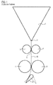
- FIG. 1 shows a section of a known folding structure of a web offset printing press.
- This folding structure comprises, inter alia, a former 1, with which a paper web strand or several paper web strands, which are guided via the former 1, are provided with a longitudinal fold. On the one or more paper web strands two printed pages are usually available side by side.
- a six-page wide printing press eg 6-2
- an eight-page wide press eg 8-2 or 8-3
- three or four such former 1 preferably adjacent to each other, can be arranged.
- the one or more paper web strands are thus guided over the former 1 and are provided below the funnel nose 2 with a longitudinal fold.
- the longitudinally folded paper web is denoted by 6.
- the two funnel inlet rollers 3 and 4 close, forming a so-called inlet gap 5.
- the main function of the hopper infeed rollers 3 and 4 is to assist the formation of the longitudinal fold of the former 1.
- the longitudinally folded paper web 6 is actively conveyed to the folding unit by means of the two draw rollers 7 and 8.
- the folder is in FIG. 1 not shown.
- baffle 9 in FIG. 1 deflects the paper strand 6 to the left. This in FIG. 1 dashed line baffle would deflect the paper web 6 to the right.
- Adjusting the baffles 9 requires engagement of an operator in the folder assembly.
- the individual folded and cut sheets are transferred to the sheet delivery over a paddle wheel to a conveyor belt.
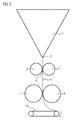
- FIG. 2 shows a new folding structure with a web transport device 10.
- This folding structure is the Falzied from FIG. 1 similar and also comprises at least one former 1, with which a paper web strand or the plurality of paper web strands, which are guided via the former 1, are provided with a longitudinal fold.
- the two hopper inlet rollers 3 and 4 which form a so-called inlet gap 5, also follow.
- the main function of the hopper infeed rollers 3 and 4 is to assist the formation of the longitudinal fold of the former 1.
- the hopper infeed rollers 3 and 4 are equipped with a drive not facilitating paper web feeding FIG. 2 is shown.
- the longitudinally folded paper web 6 is actively conveyed to the folding unit by means of the two draw rollers 7 and 8.
- the folder is in FIG. 1 not shown.
- a conveyor belt 10 is used, which is located in FIG. 2 rotates clockwise to move the paper web 6 to the right side. If the conveyor belt 10 rotates counterclockwise, the paper web 6 can be conveyed to the left side.
- the individual sheets are transferred to the sheet delivery on a paddle wheel to a conveyor belt.
- the inventor expressly points out that the conveyor belt on the sheet delivery, which removes the already cut sheets, should not be confused the conveyor belt 10.
- the conveyor belt 10 conveys the still uncut paper strand 6 and no pre-assembled sheets.
Landscapes
- Engineering & Computer Science (AREA)
- Mechanical Engineering (AREA)
- Folding Of Thin Sheet-Like Materials, Special Discharging Devices, And Others (AREA)
Applications Claiming Priority (1)
| Application Number | Priority Date | Filing Date | Title |
|---|---|---|---|
| DE102008012034A DE102008012034A1 (de) | 2008-02-29 | 2008-02-29 | Falzaufbau einer Rollenrotationsdruckmaschine und Verfahren zum Betreiben desselben |
Publications (1)
| Publication Number | Publication Date |
|---|---|
| EP2095952A1 true EP2095952A1 (fr) | 2009-09-02 |
Family
ID=40673132
Family Applications (1)
| Application Number | Title | Priority Date | Filing Date |
|---|---|---|---|
| EP09153006A Withdrawn EP2095952A1 (fr) | 2008-02-29 | 2009-02-17 | Dispositif de pliage d'une presse d'impression rotative et procédé destiné au fonctionnement de celui-ci |
Country Status (3)
| Country | Link |
|---|---|
| US (1) | US7981018B2 (fr) |
| EP (1) | EP2095952A1 (fr) |
| DE (1) | DE102008012034A1 (fr) |
Citations (4)
| Publication number | Priority date | Publication date | Assignee | Title |
|---|---|---|---|---|
| US2449234A (en) * | 1947-05-20 | 1948-09-14 | Roofing Machinery Mfg Company | Winder apparatus |
| JPH0475967A (ja) * | 1990-07-18 | 1992-03-10 | Komori Corp | 折機 |
| EP0890538A1 (fr) * | 1997-07-10 | 1999-01-13 | Voith Sulzer Finishing GmbH | Refendeuse |
| DE10163211A1 (de) * | 2001-12-21 | 2003-07-10 | Koenig & Bauer Ag | Vorrichtung zur Herstellung von Falzprodukten |
Family Cites Families (7)
| Publication number | Priority date | Publication date | Assignee | Title |
|---|---|---|---|---|
| DE4229059C2 (de) * | 1992-09-01 | 1996-07-11 | Koenig & Bauer Albert Ag | Falzapparat für Rollen-Rotationsdruckmaschinen |
| DE4242542A1 (de) * | 1992-12-16 | 1994-06-23 | Heidelberger Druckmasch Ag | Produktauslagesystem für Falzapparate an Rotationsdruckmaschinen |
| FR2711576B1 (fr) * | 1993-10-26 | 1996-01-19 | Heidelberg Harris Sa | Dispositif de commande de l'accumulation ou non accumulation d'un cylindre coupeur-accumulateur d'une plieuse. |
| DE19719553A1 (de) * | 1997-05-09 | 1998-11-12 | Koenig & Bauer Albert Ag | Falzapparat |
| DE10116346B4 (de) * | 2001-04-02 | 2006-03-02 | Koenig & Bauer Ag | Falzapparat |
| DE10164778A1 (de) * | 2001-12-21 | 2003-07-10 | Koenig & Bauer Ag | Vorrichtung zur Herstellung von Falzprodukten |
| JP2008007294A (ja) * | 2006-06-30 | 2008-01-17 | Komori Corp | 折機 |
-
2008
- 2008-02-29 DE DE102008012034A patent/DE102008012034A1/de not_active Withdrawn
-
2009
- 2009-02-17 EP EP09153006A patent/EP2095952A1/fr not_active Withdrawn
- 2009-02-27 US US12/394,556 patent/US7981018B2/en not_active Expired - Fee Related
Patent Citations (4)
| Publication number | Priority date | Publication date | Assignee | Title |
|---|---|---|---|---|
| US2449234A (en) * | 1947-05-20 | 1948-09-14 | Roofing Machinery Mfg Company | Winder apparatus |
| JPH0475967A (ja) * | 1990-07-18 | 1992-03-10 | Komori Corp | 折機 |
| EP0890538A1 (fr) * | 1997-07-10 | 1999-01-13 | Voith Sulzer Finishing GmbH | Refendeuse |
| DE10163211A1 (de) * | 2001-12-21 | 2003-07-10 | Koenig & Bauer Ag | Vorrichtung zur Herstellung von Falzprodukten |
Also Published As
| Publication number | Publication date |
|---|---|
| US7981018B2 (en) | 2011-07-19 |
| DE102008012034A1 (de) | 2009-09-03 |
| US20090221410A1 (en) | 2009-09-03 |
Similar Documents
| Publication | Publication Date | Title |
|---|---|---|
| EP0165599B1 (fr) | Plieuse pour la coupe à demi-circonférence dans une rotative à bobines | |
| DE10003025C1 (de) | Falzapparat | |
| EP1110724B1 (fr) | Dispositif pour enfiler une bande de papier | |
| EP0211377B1 (fr) | Dispositif pour plier transversalement des produits imprimés | |
| EP0089407B1 (fr) | Dispositif pour diviser un courant de produits imprimés | |
| EP0243720B1 (fr) | Appareil de pliage avec un deuxième et troisième pli | |
| DE10033467A1 (de) | Falzapparatanordnung in einer Rollenrotations-Zeitungsdruckmaschine | |
| DE4313938A1 (de) | Falzapparat für Rotationsdruckmaschinen | |
| EP1137588B1 (fr) | Dispositif d'amenee de bandes de matiere pour appareil de pliage | |
| EP0210633A2 (fr) | Dispositif de pliage avec assemblage avant le troisième pli | |
| EP1764232B1 (fr) | Méthode et dispositif pour la fabrication des journaux imprimés de façon numérique | |
| EP0932573A1 (fr) | Machine de traitement de feuilles | |
| EP2517995B1 (fr) | Plieuse avec dispositif de transport | |
| DE4202363C2 (de) | Vorrichtung zum Trennen einer auch aus mehreren Teilbahnen bestehenden Bahn in Abschnitte | |
| DE10060758A1 (de) | Schneidevorrichtung mit variabler Abschnittslänge | |
| EP2319788B1 (fr) | Plieuse dotée d'un dispositif d'extraction | |
| EP2095952A1 (fr) | Dispositif de pliage d'une presse d'impression rotative et procédé destiné au fonctionnement de celui-ci | |
| EP2960193A1 (fr) | Plieuse à poches comprenant une presse intégrée | |
| DE9312170U1 (de) | Falzapparat für Rollenrotationsdruckmaschinen | |
| DE10235897A1 (de) | Bedruckstoff verarbeitende Maschine mit einer Transportbandeinrichtung | |
| DE3332809A1 (de) | Bandverzoegerungsstrecke fuer einen falzapparat | |
| DE10059587A1 (de) | Verfahren und Vorrichtung zum Falzen von Materialbogen | |
| DE10007344B4 (de) | Falzapparat mit einer Längsfalz-Vorrichtung | |
| DE506742C (de) | Vorrichtung zum Ausrichten und Zufuehren von Bogen aus Papier, Karton o. dgl. zu Arbeitsmaschinen, wie Druckpressen, Falzmaschinen o. dgl. | |
| DE3629003A1 (de) | Offset-bogendruckmaschine |
Legal Events
| Date | Code | Title | Description |
|---|---|---|---|
| PUAI | Public reference made under article 153(3) epc to a published international application that has entered the european phase |
Free format text: ORIGINAL CODE: 0009012 |
|
| AK | Designated contracting states |
Kind code of ref document: A1 Designated state(s): AT BE BG CH CY CZ DE DK EE ES FI FR GB GR HR HU IE IS IT LI LT LU LV MC MK MT NL NO PL PT RO SE SI SK TR |
|
| AX | Request for extension of the european patent |
Extension state: AL BA RS |
|
| 17P | Request for examination filed |
Effective date: 20100225 |
|
| 17Q | First examination report despatched |
Effective date: 20100326 |
|
| AKX | Designation fees paid |
Designated state(s): AT BE BG CH CY CZ DE DK EE ES FI FR GB GR HR HU IE IS IT LI LT LU LV MC MK MT NL NO PL PT RO SE SI SK TR |
|
| GRAP | Despatch of communication of intention to grant a patent |
Free format text: ORIGINAL CODE: EPIDOSNIGR1 |
|
| RIC1 | Information provided on ipc code assigned before grant |
Ipc: B65H 23/30 20060101ALI20120202BHEP Ipc: B41F 13/02 20060101ALI20120202BHEP Ipc: B65H 45/22 20060101ALI20120202BHEP Ipc: B41F 13/58 20060101AFI20120202BHEP |
|
| 19U | Interruption of proceedings before grant |
Effective date: 20120201 |
|
| 19W | Proceedings resumed before grant after interruption of proceedings |
Effective date: 20140203 |
|
| STAA | Information on the status of an ep patent application or granted ep patent |
Free format text: STATUS: THE APPLICATION HAS BEEN WITHDRAWN |
|
| 18W | Application withdrawn |
Effective date: 20140311 |