EP2095953A1 - Tintenkartuschen - Google Patents
Tintenkartuschen Download PDFInfo
- Publication number
- EP2095953A1 EP2095953A1 EP08003692A EP08003692A EP2095953A1 EP 2095953 A1 EP2095953 A1 EP 2095953A1 EP 08003692 A EP08003692 A EP 08003692A EP 08003692 A EP08003692 A EP 08003692A EP 2095953 A1 EP2095953 A1 EP 2095953A1
- Authority
- EP
- European Patent Office
- Prior art keywords
- ink
- wall
- shaft
- frame
- ink cartridge
- Prior art date
- Legal status (The legal status is an assumption and is not a legal conclusion. Google has not performed a legal analysis and makes no representation as to the accuracy of the status listed.)
- Granted
Links
Images



Classifications
-
- B—PERFORMING OPERATIONS; TRANSPORTING
- B41—PRINTING; LINING MACHINES; TYPEWRITERS; STAMPS
- B41J—TYPEWRITERS; SELECTIVE PRINTING MECHANISMS, i.e. MECHANISMS PRINTING OTHERWISE THAN FROM A FORME; CORRECTION OF TYPOGRAPHICAL ERRORS
- B41J2/00—Typewriters or selective printing mechanisms characterised by the printing or marking process for which they are designed
- B41J2/005—Typewriters or selective printing mechanisms characterised by the printing or marking process for which they are designed characterised by bringing liquid or particles selectively into contact with a printing material
- B41J2/01—Ink jet
- B41J2/17—Ink jet characterised by ink handling
- B41J2/175—Ink supply systems ; Circuit parts therefor
- B41J2/17503—Ink cartridges
- B41J2/17513—Inner structure
-
- B—PERFORMING OPERATIONS; TRANSPORTING
- B41—PRINTING; LINING MACHINES; TYPEWRITERS; STAMPS
- B41J—TYPEWRITERS; SELECTIVE PRINTING MECHANISMS, i.e. MECHANISMS PRINTING OTHERWISE THAN FROM A FORME; CORRECTION OF TYPOGRAPHICAL ERRORS
- B41J2/00—Typewriters or selective printing mechanisms characterised by the printing or marking process for which they are designed
- B41J2/005—Typewriters or selective printing mechanisms characterised by the printing or marking process for which they are designed characterised by bringing liquid or particles selectively into contact with a printing material
- B41J2/01—Ink jet
- B41J2/17—Ink jet characterised by ink handling
- B41J2/175—Ink supply systems ; Circuit parts therefor
- B41J2/17503—Ink cartridges
- B41J2/17553—Outer structure
-
- B—PERFORMING OPERATIONS; TRANSPORTING
- B41—PRINTING; LINING MACHINES; TYPEWRITERS; STAMPS
- B41J—TYPEWRITERS; SELECTIVE PRINTING MECHANISMS, i.e. MECHANISMS PRINTING OTHERWISE THAN FROM A FORME; CORRECTION OF TYPOGRAPHICAL ERRORS
- B41J2/00—Typewriters or selective printing mechanisms characterised by the printing or marking process for which they are designed
- B41J2/005—Typewriters or selective printing mechanisms characterised by the printing or marking process for which they are designed characterised by bringing liquid or particles selectively into contact with a printing material
- B41J2/01—Ink jet
- B41J2/17—Ink jet characterised by ink handling
- B41J2/175—Ink supply systems ; Circuit parts therefor
- B41J2/17566—Ink level or ink residue control
Definitions
- the present invention relates generally to ink cartridges.
- a known recording apparatus is configured to detect when an amount of ink within a known ink cartridge is less than a sufficient amount of ink.
- the ink cartridge includes an arm configured to rotate with respect to a shaft.
- the rotatable arm is configured to have a float which is positioned at a first end of the arm, and a blocking member which is positioned at a second end of the arm and is configured to move in an opposite direction with respect to the float based on an amount of ink in the ink cartridge.
- the known recording apparatus may include an optical sensor. When there is a sufficient amount of ink within the ink cartridge, the blocking member is positioned below the optical sensor, and light emitted by the optical sensor is not blocked by the blocking member.
- the blocking member moves upwards.
- the blocking member blocks the light from the optical sensor, and the printer determines that there is an insufficient amount of ink within the ink cartridge.
- the pressure within the ink chamber is reduced, or the ink cartridge is packaged in a reduced pressure packaging arrangement to prevent gas from dissolving in the ink.
- the shaft in the ink chamber may be deformed due to the pressure differential between an interior of the ink cartridge and an exterior of the ink cartridge.
- the rotatable arm may not rotate smoothly, which may decrease the accuracy of determining whether there is a sufficient amount of ink in the ink cartridge.
- the rigidity of the ink cartridge e.g., by including metal in the frame or the like.
- increasing the rigidity of the ink cartridge may decrease the likelihood that the shaft will be deformed, such an increase in rigidity may increase the size of the ink cartridge, e.g., the thickness and the width of the ink cartridge, the weight of the ink cartridge, and the cost of the ink cartridge.
- a technical advantage of the present invention is that a shaft of a movable member, e.g., an arm, may not be deformed by a force applied due to a pressure differential between an interior of the ink cartridge and an exterior of the ink cartridge
- an ink cartridge comprises a frame, a first wall comprising a film connected to the frame, and a second wall opposite the first wall.
- the frame, the first wall, and the second wall define an ink chamber therein, and the ink chamber is configured to store ink therein.
- the ink cartridge also comprises a movable member positioned within the ink chamber, and a shaft extending between the first wall and the second wall. The movable member is configured to pivot about the shaft.
- the frame comprises a first material
- the shaft comprises a second material which is different than the first material. A rigidity of the second material is greater than a rigidity for the first material.
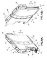
- Figs. 1(A) and 1(B) are a perspective view of a front side and a rear side, respectively, of an ink cartridge, according to the embodiment of the present invention.
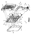
- Fig. 2 is an exploded, perspective view of the ink cartridge of Figs. 1(A) and 1(B) .
- Fig. 3 is a side view of the ink cartridge of Figs. 1(A) and 1(B) .
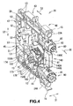
- Fig. 4 is an enlarged, perspective view of an ink container, according to an embodiment of the present invention.
- Fig. 6 is an exploded, perspective view of the ink container of Fig. 4 .
- Fig. 7 is a perspective view of an arm, according to an embodiment of the present
- an ink cartridge 10 may be configured to be removably mounted to an ink jet recording apparatus (not shown), such as an ink jet printer. Specifically, ink cartridge 10 may be mounted in a cartridge storage section (not shown) of the recording apparatus when ink cartridge 10 is inserted in a direction of insertion 30.
- the ink cartridge 10 may have a substantially flat hexahedron shape, e.g., a substantially rectangular parallelepiped shape, and may be more narrow in a widthwise direction, as indicated by an arrow 31, than in a height direction, as indicated by an arrow 32, and a depth direction, as indicated by an arrow 33.
- the ink cartridge 10 may comprise an ink container 20, a case, e.g., a housing 26, a movable member, e.g., a slider 27, and a pair of coil springs 23 and 24, in which the housing 26 and the slider 27 may form an outer shell of the ink cartridge 10.
- the ink container 20 may comprise a frame 50, an air communication valve 80, and an ink supply valve 90.
- the housing 26 may be configured to protect the ink container 20.
- each portion of the ink container 20 other than a front surface 41 may be covered by the housing 26.
- the housing 26 may comprise a first cover 21 and a second cover 22 configured to enclose the ink container 20.
- the first cover 21 may be attached to a right side surface 46 of the ink container 20 via a plurality of engaging claws 12 positioned on the inner surface of the first cover 21, which engage engaging grooves 13 positioned on the ink container 20. Accordingly the right side surface 46 of the ink container 20 is covered by the first cover 21.
- the second cover 22 is attached to a left side surface 45 of the ink container 20, such that the left side surface 45 of the ink container 20 is covered by he second cover 22.
- the covers 21 and 22 may have a shape which allows covers 21 and 22 to avoid interfering with the frame 50, the air communication valve 80, and the ink supply valve 90.
- the slider 27 may be configured to protect the air communication valve 80 and the ink supply valve 90.
- the slider 27 may be removably attached to the ink container 20, and an inner surface of the slider 27 may contact the coil springs 23 and 24.
- the coil spring 23 may be mounted to a spring receiver 23A formed at the upper portion of the front surface 41 of the ink container 20, the coil spring 24 may be mounted to a spring receiver 24A formed at the bottom portion of the front surface 41, and the engaging claws 15 and 16 may engage a pair of engaging grooves 17 and 18, respectively, positioned on the slider 27, such that a front portion 28 of the housing 26 is covered by the slider 27.
- the slider 27 may be configured to slide in the depth direction along the front portion 28 of the housing 26. Referring to Figs. 3(A) and 3(B) , slider 27 may be configured to move between a first position, as shown in Fig. 3(B) , and a second position, as shown in Fig. 3(A) . When the slider 27 is in the first position, the slider 27 may be positioned further from the front surface 41 than when the slider 27 is in the second position. When the slider 27 is in the second position, the air intake valve 80 and the ink supply valve 90 may be exposed to the outside via a pair of openings formed in the slider 27, when the slider 27 is in the first position, the slider 27 may enclose the air communication valve 80 and the ink supply valve 90.
- the ink container 20 may have substantially the same contour and shape as the ink cartridge 10.
- the cartridge storage section may receive the ink container 20 with the slider 27 in the second position.
- the ink container 20 may comprise front surface 41, a rear surface 42 opposite the front surface 41, an upper surface 43, a lower surface 44 opposite the upper surface 43, a left side surface 45, and a right side surface 46 opposite the left side surface 45, such that surfaces 41-46 define an enclosure therein.
- An area of surfaces 45 and 46 may be greater than an area of each of surfaces 41-44.
- the ink container 20 may comprise frame 50, an arm 70, a supporting block 170, a spring member 150, the air communication valve 80, the ink supply valve 90, and at least one film 65, e.g. , a pair of films 65.
- the frame 50 may be a housing of the ink container 20 which defines surfaces 41-46.
- the frame 50 may comprise a translucent resin, e.g. , a transparent resin, and may be formed by injection molding.
- the frame 50 may comprise polypropylene, polyacetal, nylon, or the like, or any combinations thereof.
- the frame 50 may comprise an outer peripheral wall 51 and a plurality of inner walls 52.
- the inner walls 52 are arranged inside the outer peripheral wall 51.
- the outer peripheral wall 51 and the inner walls 52 may be integral with the frame 50.
- the outer peripheral wall 51 and the inner walls 52 may extend from the left side surface 45 to the right side surface 46 of the ink container 20.
- the outer peripheral wall 51 may be disposed in an annular shape along the front surface 41, the upper surface 43, the rear surface 42 and the lower surface 44 to define a space in the interior thereof. Accordingly, an opening 57 may be positioned on each of the left side surface 45 and the right side surface 46 of the frame 50.
- the pair of films 65 may be connected to, e.g. , adhered to the left side surface 45 and the right side surface 46, respectively, of the frame 50 via an adhesion method, e.g., a thermal adhesion method.
- an adhesion method e.g., a thermal adhesion method.
- the films 65 are adhered to both end portions of the outer peripheral wall 51 in the widthwise direction 31. Accordingly, the openings 57 are covered by the films 65, and a space surrounded by the outer peripheral wall 51 and the films 65 is defined as an ink chamber 100.
- a box-shaped frame which is opened on one side only may be employed instead of the frame 50. In this case, the ink chamber 100 is defined by the film 65 adhered on the opened side of the box shaped frame.
- the inner walls 52 may be surrounded by the outer peripheral wall 51.
- the frame 50 may comprise a partitioning panel 53 which partitions an upper space of the ink chamber 100 at the center in the widthwise direction 31 integrally with the outer peripheral wall 51.
- the inner walls 52 may be integral with the outer peripheral wall 51 or the partitioning panel 53.
- the films 65 may be adhered to the inner walls 52 at the both end portions in the widthwise direction 31. Accordingly, inward deformation of the films 65 may be prevented or suppressed.
- the first cover 21 and the second cover 22 may deform toward the ink container 20, deformation of the first cover 21 and the second cover 22 may be prevented or suppressed by the inner walls 52. Consequently, the ink container 20 and the films 65 may not be damaged.
- the lower portion of the ink chamber 100 e.g., a space 102, below the partitioning panel 53 may not be partitioned in the widthwise direction 31.
- the film 65 may comprise a plurality of synthetic resin films and may have a multilayer structure.
- the film 65 may have a three-layer structure having a first layer comprising polypropylene, a second layer comprising nylon, and a third layer comprising polyethylene terephthalate laminated, such that the first layer on the side of the ink chamber 100 may comprise the same material as the frame 50.
- the films 65 may comprise a pulp, a metal, a natural resin, or the like.
- a bearing plate 74 may be positioned at the center, seen in the widthwise direction, of the outer peripheral wall 51 and may protrude therefrom.
- the bearing plate 74 may be positioned at the outer peripheral wall 51 adjacent to a corner defined by the front surface 41 and the lower surface 44.
- the bearing plate 74 may be positioned at the end portion in the outer peripheral wall 51 on the side of the right side surface 46, and may protrude therefrom.
- the bearing plate 74 may have a bearing 67, e.g., a circular bearing, positioned on the surface thereof on the side of the left side surface 45.
- a shaft 77 e.g., a shaft having a column shape, may be fitted to the bearing 67, and a shaft opening 78 of the arm 70 may be fitted on the shaft 77. The other end of the shaft 77 is supported by the supporting block 170.
- An ink injection portion 105 may be positioned at the rear surface 42 of the frame 50.
- the ink injection portion 105 may have a circular hole formed therethrough, which may allow fluid communicate between the rear surface 42 and the ink chamber 100.
- the ink injection portion 105 may be integral with the frame 50 adjacent to the lower end of the rear surface 42.
- the ink injection portion 105 communicates with the ink chamber 100. Ink is injected into the ink chamber 100 through the ink injection portion 105.
- the front surface 41 of the frame 50 may have a translucent portion 140 extending therefrom.
- the translucent portion 140 may be used to detect the amount of ink stored in the ink chamber 100.
- the translucent portion 140 may be integral with the frame 50, and may comprise the same material as the frame 50.
- the translucent portion 140 may be irradiated with light by an optical sensor, such as a photo interrupter, attached to the recording apparatus.
- the optical sensor has a light-emitting element and a light-receiving element.
- the side wall 140B may be irradiated with light emitted from the light-emitting element, and light which passes through the side wall 140B may be received by the light-receiving element.
- the translucent portion 140 may protrude outward from a portion of the front surface 41 adjacent to the middle portion thereof.
- the translucent portion 140 may be defined by five wall surfaces forming a substantially rectangular shape, and the space 142 may correspond to an interior thereof, and may have a hollow rectangular box shape.
- the translucent portion 140 may be defined by a front wall 140A extending in parallel to the front surface 41, a pair of side walls 140B, an upper wall 140C, and a bottom wall 140D including.
- the width of the front wall 140A may be less than the width of the front surface 41.
- the space 142 may be in fluid communication with the ink chamber 100.
- the air communication valve 80 may be positioned above the translucent portion 140.
- the air communication valve 80 may be configured to selectively open and close a through hole 81 to allow fluid communication with the atmosphere positioned on the upper portion of the front surface 41.
- the air communication valve 80 may comprise a valve body 87, a spring 86, a sealing member 83, and a cap 85.
- the air communication valve 80 may close the through hole 81 when the ink cartridge 10 is not mounted to the recording apparatus, and may open the through hole 81 when mounted to the recording apparatus. As such, the pressure of an air layer in the ink chamber 100 is equalized with the atmospheric pressure.
- the air communication valve 80 may be replaced by a vinyl adhesive tape or film.
- the ink supply valve 90 may close the through hole 91 when the ink cartridge 10 is not mounted to the recording apparatus, and may open the through hole 91 when the ink cartridge 10 is mounted to the recording apparatus and an ink needle (not shown) applies a force to the ink supply valve 90, such that ink in the ink chamber 100 may be dispensed from the ink chamber 100 to the recording apparatus through the ink needle.
- the arm 70 may be used to determine the amount of ink stored in the ink chamber 100 is greater than a predetermined amount of ink.
- the arm 70 may comprise an indicator portion 72 which may be positioned at a first end of the arm 70.
- the indicator portion 72 may be configured to be positioned within the inner space 142 or outside the inner space 142 based on the amount of ink in the ink chamber 100.
- the arm 70 also may comprise a float portion 73 positioned at a second end of the arm 70.
- the arm 70 may have a shaft hole 78 formed therethrough at substantially a center thereof.
- the shaft 77 may be inserted into the shaft hole 78.
- the shaft 77 may be configured to rotatably support the arm 70, and may be supported by the bearing 67 positioned on the bearing plate 74 at a first end thereof, and by the supporting block 170 at second end thereof.
- the arm 70 may be rotatably supported by the shaft 77 to be pivotable in the first direction and the second direction, which is perpendicular to the widthwise direction.
- the shaft 77 may be separate from or integral with the arm 70.
- the front surface 41 of the frame 50 may have a translucent portion 140 extending therefrom.
- the translucent portion 140 may be used to detect the amount of ink stored in the ink chamber 100.
- the translucent portion 140 may be integral with the frame 50, and may comprise the same material as the frame 50.
- the translucent portion 140 may be irradiated with light by an optical sensor, such as a photo interrupter, attached to the recording apparatus.
- the optical sensor has a light-emitting element and a light-receiving element.
- the side wall 140B may be irradiated with light emitted from the light-emitting element, and light which passes through the side wall 140B may be received by the light-receiving element.
- the translucent portion 140 may protrude outward from a portion of the front surface 41 adjacent to the middle portion thereof.
- the translucent portion 140 may be defined by five wall surfaces forming a substantially rectangular shape, and the space 142 may correspond to an interior thereof, and may have a hollow rectangular box shape.
- the translucent portion 140 may be defined by a front wall 140A extending in parallel to the front surface 41, a pair of side walls 140B, an upper wall 140C, and a bottom wall 140D including.
- the width of the front wall 140A may be less than the width of the front surface 41.
- the space 142 may be in fluid communication with the ink chamber 100.
- the air communication valve 80 may be positioned above the translucent portion 140.
- the air communication valve 80 may be configured to selectively open and close a through hole 81 to allow fluid communication with the atmosphere positioned on the upper portion of the front surface 41.
- the air communication valve 80 may comprise a valve body 87, a spring 86, a sealing member 83, and a cap 85.
- the air communication valve 80 may close the through hole 81 when the ink cartridge 10 is not mounted to the recording apparatus, and may open the through hole 81 when mounted to the recording apparatus. As such, the pressure of an air layer in the ink chamber 100 is equalized with the atmospheric pressure.
- the air communication valve 80 may be replaced by a vinyl adhesive tape or film.
- the ink supply valve 90 may be positioned below the translucent portion 140.
- the ink supply valve 90 may be configured to selectively open and close a through hole 91 to allow ink to be dispensed from an interior of ink chamber 100 to an exterior of ink chamber 100.
- the ink supply valve 90 may comprise a valve body 97, a spring 96, a spring receiver 94, a sealing member 93, and a cap 95.
- the ink supply valve 90 may close the through hole 91 when the ink cartridge 10 is not mounted to the recording apparatus, and may open the through hole 91 when the ink cartridge 10 is mounted to the recording apparatus and an ink needle (not shown) applies a force to the ink supply valve 90, such that ink in the ink chamber 100 may be dispensed from the ink chamber 100 to the recording apparatus through the ink needle.
- the arm 70 may be used to determine the amount of ink stored in the ink chamber 100 is greater than a predetermined amount of ink.
- the arm 70 may comprise an indicator portion 72 which may be positioned at a first end of the arm 70.
- the indicator portion 72 may be configured to be positioned within the inner space 142 or outside the inner space 142 based on the amount of ink in the ink chamber 100.
- the arm 70 also may comprise a float portion 73 positioned at a second end of the arm 70.
- the arm 70 may have a shaft hole 78 formed therethrough at substantially a center thereof.
- the shaft 77 may be inserted into the shaft hole 78.
- the shaft 77 may be configured to rotatably support the arm 70, and may be supported by the bearing 67 positioned on the bearing plate 74 at a first end thereof, and by the supporting block 170 at second end thereof.
- the arm 70 may be rotatably supported by the shaft 77 to be pivotable in the first direction and the second direction, which are perpendicular to the widthwise direction.
- the shaft 77 may be separate from or integral with the arm 70.
- the interior of the float portion 73 may be hollow, and may float on ink for this reason.
- the float portion 73 may have a specific gravity which is less than the specific gravity of ink.
- the indicator portion 72 may be configured to indicate whether the amount of ink remaining in the ink chamber 100 is less than a sufficient amount of ink.
- the indicator portion 72 moves into the space 142 of the translucent portion 140.
- the indicator portion 72 which may contact the inner surface of the bottom wall 140D of the translucent portion 140 to prevent the further rotation thereof, and to position the arm 70 in a first position.
- the indicator portion 72 moves away from the bottom wall 140D toward a second position.
- a second portion 76 of arm 70 may have a weight which is greater than the weight of a first portion 75 extending from the shaft hole 78 toward the indicator portion 72, such that in the air, the second portion 76 is heavier than the first portion 75. Consequently, when the amount of ink within the ink chamber 100 is low enough to expose float 73 to the air, the arm 70 rotates counterclockwise in Fig. 5 about the shaft 77, and the indicator portion 72 moves out of the space 142 of the translucent portion 140 to indicate that the amount of ink in the ink chamber 100 is less than a sufficient amount of ink.
- the arm 70 When the float portion 73 is positioned in the ink, a buoyancy is generated at the float portion 73, such that the arm 70 has a tendency to rotate clockwise in Fig. 5 about the shaft 77, and the indicator portion 72 moves into the space 142 of the translucent portion 140 and is positioned at the first position abutting wall 140D, which indicates that the amount of ink in the ink chamber 100 is greater than the predetermined amount of ink.
- the arm 70 may be replaced by a floating member (not shown) to provide an indication as to whether the amount of ink in the ink chamber is greater than a sufficient amount of ink.
- the spring member 150 may be attached around the arm 70.
- the spring member 150 may be fabricated by bending a linear steel member, such as a wire or a line.
- the spring member 150 may comprise a pair of end portions 151 and 152, a pair of protecting portions 153 and 154, and a connecting portion 155.
- the spring member 150 may be fixed to the frame 50 by engaging the connecting portion 155 with a hook 131 formed on the frame 50, and inserting the end portions 151 and 152 into a hole (not shown) formed in the bearing plate 74 and a hole 183 formed in the supporting block 170, respectively.
- the spring member 150 may surround the float portion 73 of the arm 70.
- the protecting portion 153 may be positioned on the side of the left side surface 45 of the frame 50, and the protecting portion 154 may be positioned on the side of the right side surface 46, such that the both sides of the float portion 73 are surrounded by the protecting portions 153 and 154. Because the protecting portions 153 and 154 may be bent into a substantially V-shape, the protecting portions 153 and 154 may be positioned both sides of the float portions 73 independent of the position of the float portion 73 which is configured to move within the ink chamber 100 based on the amount of ink in the ink chamber 100.
- the protecting portions 153 and 154 may be resiliently deformable. Therefore, when the films 65 receive the external force are deformed toward the ink chamber 100, the protecting portions 153 and 154 deform resiliently toward the float portion 73 together with the films 65 by an external force. Nevertheless, when the external force is damped, those portions of the films 65 which deformed toward the ink chamber 100 are urged outward and away from the float portion 73 by resilient restoration.
- the method of manufacturing the ink container may comprise a first step for injecting ink into the ink chamber 100, and a second step for decreasing the pressure inside ink chamber 100 to be less than the atmospheric pressure.
- the arm 70, the shaft 77, the spring member 150, the supporting block 170, the air communication valve 80, the ink supply valve 90 may be assembled to the frame 50, and the films 65 may be adhered to the left side surface 45 and the right side surface 46 of the frame 50, respectively.
- the ink chamber 100 may comprise the ink injection portion 105 for injecting ink, and a needle (not shown) or the like for injecting ink may be connected to the ink injection portion 105 to inject a predetermined amount of ink into the ink chamber 100.
- the second step may be implemented. For example, air in the ink chamber 100 may be reduced and discharged to reduce the pressure in the ink chamber 100, ink then may be injected into the ink chamber 100 through the ink injection portion 105 using the pressure differential between the interior and the exterior of the ink chamber 100.
- This method of injecting ink may be referred to as a pressure-reducing injection method or a vacuum injection method.
- the pressure in the ink chamber 100 is reduced, dissolution of air into the ink may be prevented or substantially prevented, and generation of air bubbles in the ink chamber 100 may be prevented or substantially prevented.
- the ink cartridge 10 is removed from the package material, and is mounted to the cartridge storage section provided in the recording apparatus.
- the air communication valve 80 is opened. Consequently, the air layer in the ink chamber 100 is drawn into the atmosphere, and the external force which deforms the films 65 is faded out.
- ink in the ink container 20 When ink in the ink container 20 is consumed, ink may be refilled in the ink container 20.
- the second step described above may be omitted.
- the films 65 When ink is disappeared from the ink chamber 100, the pressure of the ink with respect to the films 65 is faded out, and hence the films 65 may deform toward the ink chamber 100. Nevertheless, because the films 65 are supported by the shaft 77, the bearing plate 74 and the supporting block 170, the films 65 may not deflect toward the space 102. Consequently, reduction of the capacity of the ink chamber 100 due to the deformation of the films 65 may be avoided, and the ink chamber 100 readily may be refilled with ink.
- the rotation of the arm 70 is also smooth, and further accurate detection of the amount of ink is achieved.
Landscapes
- Ink Jet (AREA)
Priority Applications (2)
| Application Number | Priority Date | Filing Date | Title |
|---|---|---|---|
| DE200860000756 DE602008000756D1 (de) | 2008-02-28 | 2008-02-28 | Tintenkartuschen |
| EP20080003692 EP2095953B8 (de) | 2008-02-28 | 2008-02-28 | Tintenkartuschen |
Applications Claiming Priority (1)
| Application Number | Priority Date | Filing Date | Title |
|---|---|---|---|
| EP20080003692 EP2095953B8 (de) | 2008-02-28 | 2008-02-28 | Tintenkartuschen |
Publications (3)
| Publication Number | Publication Date |
|---|---|
| EP2095953A1 true EP2095953A1 (de) | 2009-09-02 |
| EP2095953B1 EP2095953B1 (de) | 2010-03-03 |
| EP2095953B8 EP2095953B8 (de) | 2010-07-28 |
Family
ID=39399243
Family Applications (1)
| Application Number | Title | Priority Date | Filing Date |
|---|---|---|---|
| EP20080003692 Active EP2095953B8 (de) | 2008-02-28 | 2008-02-28 | Tintenkartuschen |
Country Status (2)
| Country | Link |
|---|---|
| EP (1) | EP2095953B8 (de) |
| DE (1) | DE602008000756D1 (de) |
Citations (5)
| Publication number | Priority date | Publication date | Assignee | Title |
|---|---|---|---|---|
| EP1097814A2 (de) | 1999-11-05 | 2001-05-09 | Seiko Epson Corporation | Tintenstrahlaufzeichnungsvorrichtung |
| EP1772270A2 (de) | 2005-09-29 | 2007-04-11 | Brother Kogyo Kabushiki Kaisha | Tintenpatrone |
| EP1792736A1 (de) | 2003-09-30 | 2007-06-06 | Brother Kogyo Kabushiki Kaisha | Tintenpatrone und Tintenstrahldrucker |
| EP1839873A1 (de) | 2006-03-28 | 2007-10-03 | Brother Kogyo Kabushiki Kaisha | Tintenpatrone |
| US20070229615A1 (en) | 2006-03-31 | 2007-10-04 | Brother Kogyo Kabushiki Kaisha | Ink Cartridges |
-
2008
- 2008-02-28 EP EP20080003692 patent/EP2095953B8/de active Active
- 2008-02-28 DE DE200860000756 patent/DE602008000756D1/de active Active
Patent Citations (5)
| Publication number | Priority date | Publication date | Assignee | Title |
|---|---|---|---|---|
| EP1097814A2 (de) | 1999-11-05 | 2001-05-09 | Seiko Epson Corporation | Tintenstrahlaufzeichnungsvorrichtung |
| EP1792736A1 (de) | 2003-09-30 | 2007-06-06 | Brother Kogyo Kabushiki Kaisha | Tintenpatrone und Tintenstrahldrucker |
| EP1772270A2 (de) | 2005-09-29 | 2007-04-11 | Brother Kogyo Kabushiki Kaisha | Tintenpatrone |
| EP1839873A1 (de) | 2006-03-28 | 2007-10-03 | Brother Kogyo Kabushiki Kaisha | Tintenpatrone |
| US20070229615A1 (en) | 2006-03-31 | 2007-10-04 | Brother Kogyo Kabushiki Kaisha | Ink Cartridges |
Also Published As
| Publication number | Publication date |
|---|---|
| DE602008000756D1 (de) | 2010-04-15 |
| EP2095953B8 (de) | 2010-07-28 |
| EP2095953B1 (de) | 2010-03-03 |
Similar Documents
| Publication | Publication Date | Title |
|---|---|---|
| US8109615B2 (en) | Ink cartridges | |
| US8038275B2 (en) | Liquid containers | |
| US8157364B2 (en) | Ink cartridges and ink supply systems | |
| US8024860B2 (en) | Methods for manufacturing an ink cartridge | |
| US7815299B2 (en) | Ink cartridges | |
| US7942513B2 (en) | Ink cartridges | |
| CN101412319B (zh) | 墨盒 | |
| CN101618781B (zh) | 容器布置 | |
| EP2095959B1 (de) | Tintenpatronen und Herstellungsverfahren dafür | |
| US8079685B2 (en) | Ink cartridges and methods of manufacturing the same | |
| EP2095953B1 (de) | Tintenkartuschen | |
| EP2062733B1 (de) | Tintenpatronen | |
| US20090058959A1 (en) | Packaging arrangements | |
| EP2311641B1 (de) | Tintenpatronen | |
| EP2095957A1 (de) | Tintenpatrone | |
| EP2095956B1 (de) | Verfahren zur Herstellung einer Tintenpatrone | |
| EP2039519B1 (de) | Flüssigkeitsbehälter |
Legal Events
| Date | Code | Title | Description |
|---|---|---|---|
| PUAI | Public reference made under article 153(3) epc to a published international application that has entered the european phase |
Free format text: ORIGINAL CODE: 0009012 |
|
| 17P | Request for examination filed |
Effective date: 20090511 |
|
| AK | Designated contracting states |
Kind code of ref document: A1 Designated state(s): AT BE BG CH CY CZ DE DK EE ES FI FR GB GR HR HU IE IS IT LI LT LU LV MC MT NL NO PL PT RO SE SI SK TR |
|
| AX | Request for extension of the european patent |
Extension state: AL BA MK RS |
|
| GRAP | Despatch of communication of intention to grant a patent |
Free format text: ORIGINAL CODE: EPIDOSNIGR1 |
|
| GRAS | Grant fee paid |
Free format text: ORIGINAL CODE: EPIDOSNIGR3 |
|
| GRAA | (expected) grant |
Free format text: ORIGINAL CODE: 0009210 |
|
| AK | Designated contracting states |
Kind code of ref document: B1 Designated state(s): DE FR GB NL |
|
| REG | Reference to a national code |
Ref country code: GB Ref legal event code: FG4D |
|
| REF | Corresponds to: |
Ref document number: 602008000756 Country of ref document: DE Date of ref document: 20100415 Kind code of ref document: P |
|
| AKX | Designation fees paid |
Designated state(s): DE FR GB NL |
|
| REG | Reference to a national code |
Ref country code: NL Ref legal event code: T3 |
|
| RIN2 | Information on inventor provided after grant (corrected) |
Inventor name: KANBE, TOMOHIRO Inventor name: HATTORI, SHINGO |
|
| PLBE | No opposition filed within time limit |
Free format text: ORIGINAL CODE: 0009261 |
|
| STAA | Information on the status of an ep patent application or granted ep patent |
Free format text: STATUS: NO OPPOSITION FILED WITHIN TIME LIMIT |
|
| 26N | No opposition filed |
Effective date: 20101206 |
|
| REG | Reference to a national code |
Ref country code: FR Ref legal event code: PLFP Year of fee payment: 9 |
|
| REG | Reference to a national code |
Ref country code: FR Ref legal event code: PLFP Year of fee payment: 10 |
|
| REG | Reference to a national code |
Ref country code: FR Ref legal event code: PLFP Year of fee payment: 11 |
|
| PGFP | Annual fee paid to national office [announced via postgrant information from national office to epo] |
Ref country code: GB Payment date: 20180125 Year of fee payment: 11 |
|
| PGFP | Annual fee paid to national office [announced via postgrant information from national office to epo] |
Ref country code: FR Payment date: 20180118 Year of fee payment: 11 |
|
| GBPC | Gb: european patent ceased through non-payment of renewal fee |
Effective date: 20190228 |
|
| PG25 | Lapsed in a contracting state [announced via postgrant information from national office to epo] |
Ref country code: GB Free format text: LAPSE BECAUSE OF NON-PAYMENT OF DUE FEES Effective date: 20190228 |
|
| PG25 | Lapsed in a contracting state [announced via postgrant information from national office to epo] |
Ref country code: FR Free format text: LAPSE BECAUSE OF NON-PAYMENT OF DUE FEES Effective date: 20190228 |
|
| PGFP | Annual fee paid to national office [announced via postgrant information from national office to epo] |
Ref country code: NL Payment date: 20200130 Year of fee payment: 13 |
|
| REG | Reference to a national code |
Ref country code: NL Ref legal event code: MM Effective date: 20210301 |
|
| PG25 | Lapsed in a contracting state [announced via postgrant information from national office to epo] |
Ref country code: NL Free format text: LAPSE BECAUSE OF NON-PAYMENT OF DUE FEES Effective date: 20210301 |
|
| PGFP | Annual fee paid to national office [announced via postgrant information from national office to epo] |
Ref country code: DE Payment date: 20250109 Year of fee payment: 18 |