EP2096009A2 - Cylindre de moyen d'impression pour un système d'actionnement hydraulique d'un véhicule automobile - Google Patents
Cylindre de moyen d'impression pour un système d'actionnement hydraulique d'un véhicule automobile Download PDFInfo
- Publication number
- EP2096009A2 EP2096009A2 EP09153199A EP09153199A EP2096009A2 EP 2096009 A2 EP2096009 A2 EP 2096009A2 EP 09153199 A EP09153199 A EP 09153199A EP 09153199 A EP09153199 A EP 09153199A EP 2096009 A2 EP2096009 A2 EP 2096009A2
- Authority
- EP
- European Patent Office
- Prior art keywords
- seal
- housing
- guide sleeve
- piston
- cylinder
- Prior art date
- Legal status (The legal status is an assumption and is not a legal conclusion. Google has not performed a legal analysis and makes no representation as to the accuracy of the status listed.)
- Granted
Links
- 125000006850 spacer group Chemical group 0.000 claims abstract description 27
- 239000000463 material Substances 0.000 claims description 4
- 239000002131 composite material Substances 0.000 claims description 3
- 238000007789 sealing Methods 0.000 description 24
- 239000012530 fluid Substances 0.000 description 10
- 238000009434 installation Methods 0.000 description 7
- 229920001971 elastomer Polymers 0.000 description 6
- 239000000806 elastomer Substances 0.000 description 6
- 239000011324 bead Substances 0.000 description 3
- 239000013536 elastomeric material Substances 0.000 description 3
- 238000002347 injection Methods 0.000 description 3
- 239000007924 injection Substances 0.000 description 3
- 238000004026 adhesive bonding Methods 0.000 description 2
- 238000010276 construction Methods 0.000 description 2
- 238000011161 development Methods 0.000 description 2
- 230000018109 developmental process Effects 0.000 description 2
- 238000001746 injection moulding Methods 0.000 description 2
- 238000000034 method Methods 0.000 description 2
- 229920002943 EPDM rubber Polymers 0.000 description 1
- 230000007547 defect Effects 0.000 description 1
- 230000001419 dependent effect Effects 0.000 description 1
- 230000002349 favourable effect Effects 0.000 description 1
- 238000000465 moulding Methods 0.000 description 1
- 230000002093 peripheral effect Effects 0.000 description 1
- 230000000630 rising effect Effects 0.000 description 1
- 238000004073 vulcanization Methods 0.000 description 1
- 238000009736 wetting Methods 0.000 description 1
Images


Classifications
-
- F—MECHANICAL ENGINEERING; LIGHTING; HEATING; WEAPONS; BLASTING
- F16—ENGINEERING ELEMENTS AND UNITS; GENERAL MEASURES FOR PRODUCING AND MAINTAINING EFFECTIVE FUNCTIONING OF MACHINES OR INSTALLATIONS; THERMAL INSULATION IN GENERAL
- F16J—PISTONS; CYLINDERS; SEALINGS
- F16J15/00—Sealings
- F16J15/16—Sealings between relatively-moving surfaces
- F16J15/32—Sealings between relatively-moving surfaces with elastic sealings, e.g. O-rings
- F16J15/3204—Sealings between relatively-moving surfaces with elastic sealings, e.g. O-rings with at least one lip
- F16J15/3232—Sealings between relatively-moving surfaces with elastic sealings, e.g. O-rings with at least one lip having two or more lips
- F16J15/3236—Sealings between relatively-moving surfaces with elastic sealings, e.g. O-rings with at least one lip having two or more lips with at least one lip for each surface, e.g. U-cup packings
-
- B—PERFORMING OPERATIONS; TRANSPORTING
- B60—VEHICLES IN GENERAL
- B60T—VEHICLE BRAKE CONTROL SYSTEMS OR PARTS THEREOF; BRAKE CONTROL SYSTEMS OR PARTS THEREOF, IN GENERAL; ARRANGEMENT OF BRAKING ELEMENTS ON VEHICLES IN GENERAL; PORTABLE DEVICES FOR PREVENTING UNWANTED MOVEMENT OF VEHICLES; VEHICLE MODIFICATIONS TO FACILITATE COOLING OF BRAKES
- B60T11/00—Transmitting braking action from initiating means to ultimate brake actuator without power assistance or drive or where such assistance or drive is irrelevant
- B60T11/10—Transmitting braking action from initiating means to ultimate brake actuator without power assistance or drive or where such assistance or drive is irrelevant transmitting by fluid means, e.g. hydraulic
- B60T11/16—Master control, e.g. master cylinders
- B60T11/236—Piston sealing arrangements
-
- F—MECHANICAL ENGINEERING; LIGHTING; HEATING; WEAPONS; BLASTING
- F15—FLUID-PRESSURE ACTUATORS; HYDRAULICS OR PNEUMATICS IN GENERAL
- F15B—SYSTEMS ACTING BY MEANS OF FLUIDS IN GENERAL; FLUID-PRESSURE ACTUATORS, e.g. SERVOMOTORS; DETAILS OF FLUID-PRESSURE SYSTEMS, NOT OTHERWISE PROVIDED FOR
- F15B15/00—Fluid-actuated devices for displacing a member from one position to another; Gearing associated therewith
- F15B15/08—Characterised by the construction of the motor unit
- F15B15/14—Characterised by the construction of the motor unit of the straight-cylinder type
- F15B15/1423—Component parts; Constructional details
- F15B15/1428—Cylinders
-
- F—MECHANICAL ENGINEERING; LIGHTING; HEATING; WEAPONS; BLASTING
- F15—FLUID-PRESSURE ACTUATORS; HYDRAULICS OR PNEUMATICS IN GENERAL
- F15B—SYSTEMS ACTING BY MEANS OF FLUIDS IN GENERAL; FLUID-PRESSURE ACTUATORS, e.g. SERVOMOTORS; DETAILS OF FLUID-PRESSURE SYSTEMS, NOT OTHERWISE PROVIDED FOR
- F15B15/00—Fluid-actuated devices for displacing a member from one position to another; Gearing associated therewith
- F15B15/08—Characterised by the construction of the motor unit
- F15B15/14—Characterised by the construction of the motor unit of the straight-cylinder type
- F15B15/1423—Component parts; Constructional details
- F15B15/1457—Piston rods
- F15B15/1461—Piston rod sealings
-
- F—MECHANICAL ENGINEERING; LIGHTING; HEATING; WEAPONS; BLASTING
- F16—ENGINEERING ELEMENTS AND UNITS; GENERAL MEASURES FOR PRODUCING AND MAINTAINING EFFECTIVE FUNCTIONING OF MACHINES OR INSTALLATIONS; THERMAL INSULATION IN GENERAL
- F16D—COUPLINGS FOR TRANSMITTING ROTATION; CLUTCHES; BRAKES
- F16D25/00—Fluid-actuated clutches
- F16D25/08—Fluid-actuated clutches with fluid-actuated member not rotating with a clutching member
- F16D25/088—Fluid-actuated clutches with fluid-actuated member not rotating with a clutching member the line of action of the fluid-actuated members being distinctly separate from the axis of rotation
-
- F—MECHANICAL ENGINEERING; LIGHTING; HEATING; WEAPONS; BLASTING
- F15—FLUID-PRESSURE ACTUATORS; HYDRAULICS OR PNEUMATICS IN GENERAL
- F15B—SYSTEMS ACTING BY MEANS OF FLUIDS IN GENERAL; FLUID-PRESSURE ACTUATORS, e.g. SERVOMOTORS; DETAILS OF FLUID-PRESSURE SYSTEMS, NOT OTHERWISE PROVIDED FOR
- F15B2215/00—Fluid-actuated devices for displacing a member from one position to another
- F15B2215/30—Constructional details thereof
- F15B2215/305—Constructional details thereof characterised by the use of special materials
Definitions
- the invention relates to a pressure medium cylinder for a hydraulic actuating system of a motor vehicle.
- a defined according to the preamble of claim 1 pressure cylinder is usually used as a slave cylinder and a defined according to the preamble of claim 2 pressure cylinder is usually used as a master cylinder for a hydraulic clutch or brake system of a motor vehicle.
- Such pressure medium cylinders are for example from the DE 103 52 941 A1 or the EP 1 602 544 A1 known.
- the invention has the task of providing pressure medium cylinder with a simplified and assembly-safe design.
- a first pressure medium cylinder for a hydraulic actuating system of a motor vehicle, which comprises a housing with an inner cylinder and with a pressure port and further connected to the housing fixed guide sleeve, which forms a common sleeve with the inner cylinder of the housing and one in the bushing displaceably arranged piston which limits a variable pressure chamber.
- a housing-fixed first seal which cooperates with the piston and with the housing or with a fixedly connected to the housing component.
- the pressure cylinder according to the invention is characterized in that the first seal is made of a material fit with the guide sleeve.
- the cohesive connection of the guide sleeve and the seal made of an elastomeric material is carried out before the assembly of the pressure cylinder, e.g. by gluing, scorching or by injection of an elastomer to the guide sleeve. In this way, the number of parts of a pressure cylinder is reduced and a related assembly error is excluded.
- a second pressure medium cylinder for a hydraulic actuating system of a motor vehicle, which comprises a housing with an inner cylinder and a pressure port, further connected to the housing guide sleeve, which forms a common sleeve with the inner cylinder of the housing and one in the bushing displaceably arranged piston which limits a variable pressure chamber.
- a housing-fixed first seal which cooperates with the piston and with the housing or with a fixedly connected to the housing component.
- the pressure cylinder comprises a second housing-fixed seal acting between the piston and the housing, which is arranged axially spaced from the first seal by a spacer element.
- the pressure medium cylinder is characterized in that the spacer element is designed as part of the guide sleeve.
- the spacer element may be formed, for example, as an annular axial extension of the guide sleeve or in the form of segmented axial projections.
- fluid passages for the subsequent flow of fluid from a reservoir connected to the pressure medium cylinder and for the largest possible flow around or wetting of the piston can advantageously be provided by corresponding recesses.
- the number of components to be mounted for a pressure medium cylinder is reduced.
- a one-piece design of guide sleeve and spacer thus eliminates the same assembly errors due to a faulty mutual position and positioning inaccuracies of the previously separately available parts.
- the primary and secondary seals can be arranged as individual seals already before assembly in the housing of the pressure cylinder on the extension sleeve to the guide sleeve.
- two axially spaced and radially staggered receiving portions for the arrangement of the primary and the secondary seal can be provided on the guide sleeve.
- the receiving portion of the primary seal may be provided at the free end of the spacer element, whereas for the arrangement of the secondary seal, a radially inner and axially shorter receiving portion is provided for the spacer element.
- At least one of the primary and secondary seals is designed as a material fit with the guide sleeve, for example by means of adhesive bonding, by vulcanization or by injection of an elastomer onto the guide sleeve or to the spacer element. If both the primary and the secondary seal are integrally connected to the guide sleeve, thus a complete seal cartridge for immediate installation in the cylinder housing is provided, whereby the handling of individual seals omitted and the assembly of a pressure cylinder is even further simplified.
- first and the second seal can also be designed as a common composite for mounting on the guide sleeve, so instead of previously two single seals a single, the primary and the secondary seal comprehensive seal package is present.
- the assembly process itself it proves to be favorable to first perform the piston through the guide sleeve, then to push the seal package first on the piston and further on the integrally formed on the guide sleeve spacer.
- a third, third housing-tight seal provided which, for example, as in the EP 1 602 544 A1 is carried out separately.
- the third seal is executed in unit with the first seal, wherein in a ring lip seal the radially outer sealing lip or the sealing portion located there can optionally be performed with an additional sealing bead on the cylinder housing and wherein the radially inner sealing lip on Piston and the sealing lips connecting base portion may rest against the guide sleeve.
- Fig. 1 shows a known, designed as a slave cylinder pressure cylinder 10 for a hydraulic actuation system of a motor vehicle.
- the slave cylinder 10 comprises a plastic housing 12 with a stepped bore, which has a front portion 14a and a rear portion 14b and wherein on the housing 12, a pressure port 16 is formed for connection to a hydraulic master cylinder.
- a guide sleeve 18 made with a through-hole 18a is inserted and firmly locked until mutual engagement of hook-shaped stopper members 20a, b formed thereon and the housing 12, and in the assembled state, the two inner cylinders of the bores 14a, 18a form a common inner liner for a displaceably arranged piston 22 therein.
- the slave cylinder 10 a of the piston 22 and of the inner wall of the housing 12 limited variable pressure chamber 24th
- a ring lip seal 26 arranged on a shoulder 12a of the housing 12 in the area of the diameter step serves to abut the housing 12 with a radially inner sealing lip 26a on the piston 22 and with a radially outer sealing lip 26b.
- both sealing lips 26a, 26b connecting base portion 26c abuts against the guide sleeve 18, so that even between the housing 12 and the guide sleeve 18 remaining annular gap with respect to the pressure chamber 24 is securely sealed.
- the piston 22 has a trained as a deep-drawn, unilaterally executed with a bottom 28a metallic piston skirt sleeve 28, from which an insert made of plastic 30 is received. With the piston 22 is pivotally connected via a designed as a ball socket 32 on the insert member 30 receiving arrangement a piston rod 34 with a spherical cap 34a, which can be brought into operative connection with a clutch fork or the like and other release means of a vehicle clutch.
- the slave cylinder 10 further has a laterally arranged on the housing 12 flange 36 for receiving a bleeder valve, not shown in the drawing.
- Fig. 1 illustrated pressure cylinder 10
- the annular lip seal 26 cohesively by injection molding an elastomeric material with the guide sleeve 18 perform.
- the composite component 18, 26 created in this way thus replaces the separate annular lip seal 26 and the separate guide sleeve 18, wherein the pressure medium cylinder 10 can be maintained otherwise unchanged.
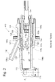
- the Fig. 2 shows an axial sectional view of another known pressure medium cylinder 110 with a tracking device, which is designed here as a master cylinder for a hydraulic actuator for actuating a motor vehicle clutch.
- the master cylinder 110 includes as in Fig. 1 Slave cylinder 10 shown a plastic housing 112 having a front portion 114a and a rear portion 114b having stepped bore and with a pressure port 116 for connection to a hydraulic slave cylinder.
- a manufactured with a through hole 118a guide sleeve 118 is inserted and connected to engage a formed on this and the housing 112, not graphically visible locking means and connected so that it is fixed axially in both directions on the housing 112.
- the piston 122 of the master cylinder 110 is connected via a pivotally arranged on this piston rod 134 with a clutch pedal, not shown in operative connection, upon actuation, the piston 122 moves in the figure to the left and via the fluid connection to the slave cylinder and a connected thereto Clutch fork for disengaging the vehicle clutch controls.
- a follower port 150 From the lateral surface of the housing 112 is from a follower port 150, which can communicate with a running therein run-off channel 150a with a drawing here not shown fluid supply tank.
- the secondary seal 126 can also be arranged directly in the housing 112 and also also abut the piston 122 and the guide tube 118.
- the spacing element 152 rests on the piston except for fluid channels provided therein, so that reliable guidance of the piston 122 is ensured in this section as well.
- another sealing element 156 manufactured as an O-ring seal is used to seal the overflow space 154.
- follower means are on the piston running surface in the form of an open compensating or follower grooves 158 extending in the axial direction from its end face. The extent is selected so that the primary seal 127 is bridged in the illustrated end position of the piston 122 and a compensation channel is released starting from the pressure chamber 124 via the Nachlaufnuten 158 to the follow-up space 154 and further to the follower passage 150 a.
- the fluid connection between the follow-up space 154 and the trailing channel 150 a and the pressure chamber 124 is through in the Fig. 3 concealed axial channels in the intermediate ring or spacer 152 ensured.
- the follower groove 158 is moved out of the area of the primary seal 127, whereby the primary seal 127 completely engages the piston running surface and thus interrupts the connection between the pressure chamber 124 and the follower passage 150a.
- the follower means can also be performed at the position shown as a closed groove, ie essentially as an axial bore, which is connected to a radially outwardly guided lateral bore, ie a branch channel.
- the branch canal then flows into the in Fig. 2 shown piston position directly behind the cooperating with the piston 122 sealing lip 127b of the primary seal 127 in the follow-up space 154.
- In the upper wall of the pressure chamber 124 is in support of the vent a rising in the direction of the primary seal 127 vent groove 1 58 arranged.
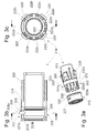
- Fig. 3 shows a guide sleeve 218, which can be connected by means of latching hooks 220 fixed to the housing 112.
- latching hooks 220 fixed to the housing 112.
- the locking hooks 220 in corresponding thereto on the cylinder housing of the pressure cylinder after Fig. 2 trained, but there not graphically engage window.
- a plurality of circumferentially spaced axial projections 222a-e are formed in the radially outer region, which act as a spacer element 252 for spacing the primary 127 and the secondary seal 126. It can be seen that the distance between the in the Fig. 3 Upwardly located axial projections 222a, b is made larger compared to the other distances, whereby a recess 222f is formed.
- the sealing package 225 shown in extension of the axial projections 222a-e comprises a primary 227, a secondary seal 226 and a sealing bead 256 formed on the latter, which function as the ring seal 156 according to FIG Fig. 2 takes over.
- the sealing package 225 is produced by molding an elastomer, for example EPDM, on the guide sleeve 218, in particular in the region of the axial projections 222a-e provided there.
- the seal pack 225 has been shown separately from the guide sleeve 218 for ease of illustration.
- the axial projections 222a-e become contiguous Elastomer part radially encapsulated on both sides, wherein the elastomer langlochfömige recesses 223 penetrates the axial projections 222a-e.
- the assembly 218, 225 produced in this way is in Fig. 3b in a longitudinal and in Fig. 3c shown in a cross section.
- the molded elastomer body 225 includes a primary seal portion 227 having a radially outer seal lip 227a and an inner radial seal lip 227b, and further a secondary seal portion 226 having an outer bead 256 and an inner seal lip 226b.
- the formerly outer sealing lip 126a of the seal 126 in FIG Fig. 2 is extended to a pipe section 228 and thus forms the base portion of the primary seal 227.
- the pipe section 228 has over a peripheral region on an approximately slot-shaped recess 228a, which coincides with the recess 222f on the guide sleeve 218 or is arranged there.
- the recess 228a is thus part of the follow-up space for trailing fluid in the pressure fluid cylinder.
- radially inwardly directed sections that terminate on a common pitch circle with the diameter of the bushing can additionally be provided.
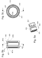
- molded onto the guide sleeve 218 seal package 225 this can also be prepared separately in advance and arranged on the guide sleeve 318, more precisely the distance element executed there 352, as in the 4a-c shown.
- the axial projections 322a-d for forming the spacer element 352 are again in this case as already described above formed with gaps, but recesses 223 (FIG. 3a-c ) within the axial projections 322a-d are not performed here.
- At the seal package 325 are corresponding to the axial projections 322a-e, in the Fig. 4a formed concealed pockets, in which the axial projections 322a-e engage when pushing the seal package 325.
- the Fig. 4b, c show in addition to an axial and a radial section, with the same or equivalent parts with a respect to the Fig. 3a-c in the first place, change from "2" to "3".
- Fig. 5a-c is shown as a further variant of a sealing packet 325 a separately manufactured from the guide sleeve, annular spacer element 452, which is encapsulated to form a primary 327 and a secondary seal 426 of an elastomeric material.
- the reference numerals of the others, to the Fig. 3 . 4 the same or equivalent parts have been changed to "4" in the first digit. It results from this construction, the advantage that for different types of pressure fluid cylinders, the same seal package can be used, whereas the housing and the guide sleeve can be adapted to the particular application.
- this spacer element in the master cylinder according to Fig. 2 is there only the guide sleeve 118 in the region of the secondary seal 126 to modify.
Landscapes
- Engineering & Computer Science (AREA)
- General Engineering & Computer Science (AREA)
- Mechanical Engineering (AREA)
- Physics & Mathematics (AREA)
- Fluid Mechanics (AREA)
- Transportation (AREA)
- Actuator (AREA)
- Hydraulic Clutches, Magnetic Clutches, Fluid Clutches, And Fluid Joints (AREA)
- Transmission Of Braking Force In Braking Systems (AREA)
- Sealing Devices (AREA)
- Fluid-Damping Devices (AREA)
Applications Claiming Priority (1)
| Application Number | Priority Date | Filing Date | Title |
|---|---|---|---|
| DE102008011132A DE102008011132A1 (de) | 2008-02-26 | 2008-02-26 | Druckmittelzylinder für ein hydraulisches Betätigungssystem eines Kraftfahrzeuges |
Publications (3)
| Publication Number | Publication Date |
|---|---|
| EP2096009A2 true EP2096009A2 (fr) | 2009-09-02 |
| EP2096009A3 EP2096009A3 (fr) | 2010-12-22 |
| EP2096009B1 EP2096009B1 (fr) | 2011-07-20 |
Family
ID=40459729
Family Applications (1)
| Application Number | Title | Priority Date | Filing Date |
|---|---|---|---|
| EP09153199A Not-in-force EP2096009B1 (fr) | 2008-02-26 | 2009-02-19 | Cylindre de moyen d'impression pour un système d'actionnement hydraulique d'un véhicule automobile |
Country Status (3)
| Country | Link |
|---|---|
| EP (1) | EP2096009B1 (fr) |
| AT (1) | ATE517004T1 (fr) |
| DE (1) | DE102008011132A1 (fr) |
Families Citing this family (3)
| Publication number | Priority date | Publication date | Assignee | Title |
|---|---|---|---|---|
| DE102012021077A1 (de) * | 2012-10-19 | 2014-04-24 | Geräte- und Pumpenbau GmbH | Dichtungseinrichtung für Stangen |
| DE102020112629A1 (de) | 2020-05-11 | 2021-11-11 | Schaeffler Technologies AG & Co. KG | Geberzylinder |
| DE102021208531B3 (de) * | 2021-08-05 | 2022-11-10 | Trelleborg Sealing Solutions Germany Gmbh | Geberkolben, hydraulische Fahrzeugbremse und Verfahren zum Herstellen des Geberkolbens |
Citations (3)
| Publication number | Priority date | Publication date | Assignee | Title |
|---|---|---|---|---|
| DE10352941A1 (de) | 2003-11-11 | 2005-06-09 | Zf Friedrichshafen Ag | Druckmittelzylinder für eine hydraulische Betätigunseinrichtung |
| EP1602544A1 (fr) | 2004-06-04 | 2005-12-07 | Zf Friedrichshafen Ag | Maítre-cylindre hydraulique |
| DE19680491B4 (de) | 1995-06-27 | 2006-09-21 | Luk Lamellen Und Kupplungsbau Beteiligungs Kg | Abdichtungen in einem Geberzylinder |
Family Cites Families (3)
| Publication number | Priority date | Publication date | Assignee | Title |
|---|---|---|---|---|
| GB1009261A (en) * | 1961-10-17 | 1965-11-10 | Automotive Prod Co Ltd | Improvements in and relating to fluid pressure master cylinders |
| US7219495B2 (en) * | 2004-06-04 | 2007-05-22 | Zf Friedrichshafen Ag | Hydraulic cylinder |
| DE102006030450A1 (de) * | 2006-06-29 | 2008-01-03 | Fte Automotive Gmbh | Hydraulische Stellvorrichtung für die Betätigung einer Schaltstange insbesondere eines Schaltgetriebes für Kraftfahrzeuge |
-
2008
- 2008-02-26 DE DE102008011132A patent/DE102008011132A1/de not_active Withdrawn
-
2009
- 2009-02-19 EP EP09153199A patent/EP2096009B1/fr not_active Not-in-force
- 2009-02-19 AT AT09153199T patent/ATE517004T1/de active
Patent Citations (3)
| Publication number | Priority date | Publication date | Assignee | Title |
|---|---|---|---|---|
| DE19680491B4 (de) | 1995-06-27 | 2006-09-21 | Luk Lamellen Und Kupplungsbau Beteiligungs Kg | Abdichtungen in einem Geberzylinder |
| DE10352941A1 (de) | 2003-11-11 | 2005-06-09 | Zf Friedrichshafen Ag | Druckmittelzylinder für eine hydraulische Betätigunseinrichtung |
| EP1602544A1 (fr) | 2004-06-04 | 2005-12-07 | Zf Friedrichshafen Ag | Maítre-cylindre hydraulique |
Also Published As
| Publication number | Publication date |
|---|---|
| EP2096009B1 (fr) | 2011-07-20 |
| DE102008011132A1 (de) | 2009-08-27 |
| EP2096009A3 (fr) | 2010-12-22 |
| ATE517004T1 (de) | 2011-08-15 |
Similar Documents
| Publication | Publication Date | Title |
|---|---|---|
| WO2013076146A2 (fr) | Maître-cylindre | |
| EP3478969B1 (fr) | Cylindre émetteur, en particulier pour un dispositif hydraulique d'actionnement d'embrayage dans des véhicules | |
| DE102008063241A1 (de) | Hauptzylinder | |
| DE19680491C5 (de) | Abdichtungen in einem Geberzylinder | |
| EP2566730B1 (fr) | Maître-cylindre de système de freinage hydraulique de véhicule automobile | |
| EP2096009B1 (fr) | Cylindre de moyen d'impression pour un système d'actionnement hydraulique d'un véhicule automobile | |
| EP1162119A1 (fr) | Piston pour un vérin hydraulique | |
| DE102014223596B4 (de) | Kolben-Zylinder-Anordnung für eine hydraulische Ausrückeinrichtung, insbesondere einen Geberzylinder einer Kupplungsbetätigungseinrichtung | |
| DE102021208531B3 (de) | Geberkolben, hydraulische Fahrzeugbremse und Verfahren zum Herstellen des Geberkolbens | |
| DE102004057137A1 (de) | Hauptzylinder insbesondere für ein geregeltes Bremssystem | |
| EP2836405A1 (fr) | Ensemble maître-cylindre pour un système de freinage de véhicule à moteur et élément d'étanchéité-d'étranglement d'un seul tenant pour cet ensemble | |
| DE69611890T2 (de) | Verbesserte hydraulische Kupplungsbetätigungsvorrichtung für Kraftfahrzeuge | |
| EP2330005B1 (fr) | Cylindre hydraulique | |
| DE19537038B4 (de) | Geberzylinder | |
| DE102011080924A1 (de) | Geberzylinder | |
| EP3177844A1 (fr) | Maître-cylindre comprenant une douille de guidage pour une lèvre d'étanchéité du système de dilatation | |
| DE69619351T2 (de) | Betätigungszylinder einer hydraulischen Kupplung eines Fahrzeuges | |
| EP3887216B1 (fr) | Maître-cylindre avec élément d'étanchéité | |
| WO2018145691A1 (fr) | Cylindre émetteur pourvu d'un élément d'étanchéite | |
| DE102011102301A1 (de) | Hydraulikzylinder | |
| DE29822705U1 (de) | Geberzylinder für eine Fahrzeughydraulik | |
| DE102014011047A1 (de) | Pneumatisches Zwei-Kreis-Regelventil | |
| DE19653270A1 (de) | Geberzylinder für hydraulische Betätigungssysteme | |
| EP1655192B1 (fr) | Servofrein à dépression pour véhicules automobiles | |
| DE102018009751A1 (de) | Hydraulikzylinder, insbesondere Geber- oder Nehmerzylinder für eine hydraulische Kupplungs- oder Bremsbetätigung für Kraftfahrzeuge |
Legal Events
| Date | Code | Title | Description |
|---|---|---|---|
| PUAI | Public reference made under article 153(3) epc to a published international application that has entered the european phase |
Free format text: ORIGINAL CODE: 0009012 |
|
| AK | Designated contracting states |
Kind code of ref document: A2 Designated state(s): AT BE BG CH CY CZ DE DK EE ES FI FR GB GR HR HU IE IS IT LI LT LU LV MC MK MT NL NO PL PT RO SE SI SK TR |
|
| AX | Request for extension of the european patent |
Extension state: AL BA RS |
|
| PUAL | Search report despatched |
Free format text: ORIGINAL CODE: 0009013 |
|
| AK | Designated contracting states |
Kind code of ref document: A3 Designated state(s): AT BE BG CH CY CZ DE DK EE ES FI FR GB GR HR HU IE IS IT LI LT LU LV MC MK MT NL NO PL PT RO SE SI SK TR |
|
| AX | Request for extension of the european patent |
Extension state: AL BA RS |
|
| 17P | Request for examination filed |
Effective date: 20110117 |
|
| GRAP | Despatch of communication of intention to grant a patent |
Free format text: ORIGINAL CODE: EPIDOSNIGR1 |
|
| RIC1 | Information provided on ipc code assigned before grant |
Ipc: B60T 11/236 20060101AFI20110218BHEP Ipc: F16J 15/16 20060101ALI20110218BHEP |
|
| GRAS | Grant fee paid |
Free format text: ORIGINAL CODE: EPIDOSNIGR3 |
|
| GRAA | (expected) grant |
Free format text: ORIGINAL CODE: 0009210 |
|
| AK | Designated contracting states |
Kind code of ref document: B1 Designated state(s): AT BE BG CH CY CZ DE DK EE ES FI FR GB GR HR HU IE IS IT LI LT LU LV MC MK MT NL NO PL PT RO SE SI SK TR |
|
| REG | Reference to a national code |
Ref country code: GB Ref legal event code: FG4D Free format text: NOT ENGLISH |
|
| REG | Reference to a national code |
Ref country code: CH Ref legal event code: EP |
|
| AKX | Designation fees paid |
Designated state(s): AT BE BG CH CY CZ DE DK EE ES FI FR GB GR HR HU IE IS IT LI LT LU LV MC MK MT NL NO PL PT RO SE SI SK TR |
|
| REG | Reference to a national code |
Ref country code: DE Ref legal event code: R096 Ref document number: 502009000974 Country of ref document: DE Effective date: 20110915 |
|
| REG | Reference to a national code |
Ref country code: NL Ref legal event code: VDEP Effective date: 20110720 |
|
| PG25 | Lapsed in a contracting state [announced via postgrant information from national office to epo] |
Ref country code: NL Free format text: LAPSE BECAUSE OF FAILURE TO SUBMIT A TRANSLATION OF THE DESCRIPTION OR TO PAY THE FEE WITHIN THE PRESCRIBED TIME-LIMIT Effective date: 20110720 Ref country code: PT Free format text: LAPSE BECAUSE OF FAILURE TO SUBMIT A TRANSLATION OF THE DESCRIPTION OR TO PAY THE FEE WITHIN THE PRESCRIBED TIME-LIMIT Effective date: 20111121 Ref country code: FI Free format text: LAPSE BECAUSE OF FAILURE TO SUBMIT A TRANSLATION OF THE DESCRIPTION OR TO PAY THE FEE WITHIN THE PRESCRIBED TIME-LIMIT Effective date: 20110720 Ref country code: IS Free format text: LAPSE BECAUSE OF FAILURE TO SUBMIT A TRANSLATION OF THE DESCRIPTION OR TO PAY THE FEE WITHIN THE PRESCRIBED TIME-LIMIT Effective date: 20111120 Ref country code: SE Free format text: LAPSE BECAUSE OF FAILURE TO SUBMIT A TRANSLATION OF THE DESCRIPTION OR TO PAY THE FEE WITHIN THE PRESCRIBED TIME-LIMIT Effective date: 20110720 Ref country code: LT Free format text: LAPSE BECAUSE OF FAILURE TO SUBMIT A TRANSLATION OF THE DESCRIPTION OR TO PAY THE FEE WITHIN THE PRESCRIBED TIME-LIMIT Effective date: 20110720 Ref country code: NO Free format text: LAPSE BECAUSE OF FAILURE TO SUBMIT A TRANSLATION OF THE DESCRIPTION OR TO PAY THE FEE WITHIN THE PRESCRIBED TIME-LIMIT Effective date: 20111020 Ref country code: HR Free format text: LAPSE BECAUSE OF FAILURE TO SUBMIT A TRANSLATION OF THE DESCRIPTION OR TO PAY THE FEE WITHIN THE PRESCRIBED TIME-LIMIT Effective date: 20110720 |
|
| REG | Reference to a national code |
Ref country code: IE Ref legal event code: FD4D |
|
| PG25 | Lapsed in a contracting state [announced via postgrant information from national office to epo] |
Ref country code: CY Free format text: LAPSE BECAUSE OF FAILURE TO SUBMIT A TRANSLATION OF THE DESCRIPTION OR TO PAY THE FEE WITHIN THE PRESCRIBED TIME-LIMIT Effective date: 20110720 Ref country code: SI Free format text: LAPSE BECAUSE OF FAILURE TO SUBMIT A TRANSLATION OF THE DESCRIPTION OR TO PAY THE FEE WITHIN THE PRESCRIBED TIME-LIMIT Effective date: 20110720 Ref country code: PL Free format text: LAPSE BECAUSE OF FAILURE TO SUBMIT A TRANSLATION OF THE DESCRIPTION OR TO PAY THE FEE WITHIN THE PRESCRIBED TIME-LIMIT Effective date: 20110720 Ref country code: LV Free format text: LAPSE BECAUSE OF FAILURE TO SUBMIT A TRANSLATION OF THE DESCRIPTION OR TO PAY THE FEE WITHIN THE PRESCRIBED TIME-LIMIT Effective date: 20110720 Ref country code: GR Free format text: LAPSE BECAUSE OF FAILURE TO SUBMIT A TRANSLATION OF THE DESCRIPTION OR TO PAY THE FEE WITHIN THE PRESCRIBED TIME-LIMIT Effective date: 20111021 |
|
| PG25 | Lapsed in a contracting state [announced via postgrant information from national office to epo] |
Ref country code: SK Free format text: LAPSE BECAUSE OF FAILURE TO SUBMIT A TRANSLATION OF THE DESCRIPTION OR TO PAY THE FEE WITHIN THE PRESCRIBED TIME-LIMIT Effective date: 20110720 Ref country code: CZ Free format text: LAPSE BECAUSE OF FAILURE TO SUBMIT A TRANSLATION OF THE DESCRIPTION OR TO PAY THE FEE WITHIN THE PRESCRIBED TIME-LIMIT Effective date: 20110720 Ref country code: IE Free format text: LAPSE BECAUSE OF FAILURE TO SUBMIT A TRANSLATION OF THE DESCRIPTION OR TO PAY THE FEE WITHIN THE PRESCRIBED TIME-LIMIT Effective date: 20110720 |
|
| PLBE | No opposition filed within time limit |
Free format text: ORIGINAL CODE: 0009261 |
|
| STAA | Information on the status of an ep patent application or granted ep patent |
Free format text: STATUS: NO OPPOSITION FILED WITHIN TIME LIMIT |
|
| PG25 | Lapsed in a contracting state [announced via postgrant information from national office to epo] |
Ref country code: IT Free format text: LAPSE BECAUSE OF FAILURE TO SUBMIT A TRANSLATION OF THE DESCRIPTION OR TO PAY THE FEE WITHIN THE PRESCRIBED TIME-LIMIT Effective date: 20110720 Ref country code: RO Free format text: LAPSE BECAUSE OF FAILURE TO SUBMIT A TRANSLATION OF THE DESCRIPTION OR TO PAY THE FEE WITHIN THE PRESCRIBED TIME-LIMIT Effective date: 20110720 Ref country code: EE Free format text: LAPSE BECAUSE OF FAILURE TO SUBMIT A TRANSLATION OF THE DESCRIPTION OR TO PAY THE FEE WITHIN THE PRESCRIBED TIME-LIMIT Effective date: 20110720 |
|
| 26N | No opposition filed |
Effective date: 20120423 |
|
| PG25 | Lapsed in a contracting state [announced via postgrant information from national office to epo] |
Ref country code: DK Free format text: LAPSE BECAUSE OF FAILURE TO SUBMIT A TRANSLATION OF THE DESCRIPTION OR TO PAY THE FEE WITHIN THE PRESCRIBED TIME-LIMIT Effective date: 20110720 |
|
| REG | Reference to a national code |
Ref country code: DE Ref legal event code: R097 Ref document number: 502009000974 Country of ref document: DE Effective date: 20120423 |
|
| BERE | Be: lapsed |
Owner name: ZF FRIEDRICHSHAFEN A.G. Effective date: 20120228 |
|
| PG25 | Lapsed in a contracting state [announced via postgrant information from national office to epo] |
Ref country code: MC Free format text: LAPSE BECAUSE OF NON-PAYMENT OF DUE FEES Effective date: 20120229 |
|
| REG | Reference to a national code |
Ref country code: FR Ref legal event code: ST Effective date: 20121031 |
|
| REG | Reference to a national code |
Ref country code: DE Ref legal event code: R119 Ref document number: 502009000974 Country of ref document: DE Effective date: 20120901 |
|
| PG25 | Lapsed in a contracting state [announced via postgrant information from national office to epo] |
Ref country code: BE Free format text: LAPSE BECAUSE OF NON-PAYMENT OF DUE FEES Effective date: 20120228 |
|
| PG25 | Lapsed in a contracting state [announced via postgrant information from national office to epo] |
Ref country code: FR Free format text: LAPSE BECAUSE OF NON-PAYMENT OF DUE FEES Effective date: 20120229 |
|
| PG25 | Lapsed in a contracting state [announced via postgrant information from national office to epo] |
Ref country code: MK Free format text: LAPSE BECAUSE OF FAILURE TO SUBMIT A TRANSLATION OF THE DESCRIPTION OR TO PAY THE FEE WITHIN THE PRESCRIBED TIME-LIMIT Effective date: 20110720 |
|
| PG25 | Lapsed in a contracting state [announced via postgrant information from national office to epo] |
Ref country code: ES Free format text: LAPSE BECAUSE OF FAILURE TO SUBMIT A TRANSLATION OF THE DESCRIPTION OR TO PAY THE FEE WITHIN THE PRESCRIBED TIME-LIMIT Effective date: 20111031 |
|
| PG25 | Lapsed in a contracting state [announced via postgrant information from national office to epo] |
Ref country code: BG Free format text: LAPSE BECAUSE OF FAILURE TO SUBMIT A TRANSLATION OF THE DESCRIPTION OR TO PAY THE FEE WITHIN THE PRESCRIBED TIME-LIMIT Effective date: 20111020 Ref country code: DE Free format text: LAPSE BECAUSE OF NON-PAYMENT OF DUE FEES Effective date: 20120901 |
|
| PG25 | Lapsed in a contracting state [announced via postgrant information from national office to epo] |
Ref country code: MT Free format text: LAPSE BECAUSE OF FAILURE TO SUBMIT A TRANSLATION OF THE DESCRIPTION OR TO PAY THE FEE WITHIN THE PRESCRIBED TIME-LIMIT Effective date: 20110720 |
|
| REG | Reference to a national code |
Ref country code: CH Ref legal event code: PL |
|
| GBPC | Gb: european patent ceased through non-payment of renewal fee |
Effective date: 20130219 |
|
| PG25 | Lapsed in a contracting state [announced via postgrant information from national office to epo] |
Ref country code: LI Free format text: LAPSE BECAUSE OF NON-PAYMENT OF DUE FEES Effective date: 20130228 Ref country code: CH Free format text: LAPSE BECAUSE OF NON-PAYMENT OF DUE FEES Effective date: 20130228 |
|
| PG25 | Lapsed in a contracting state [announced via postgrant information from national office to epo] |
Ref country code: GB Free format text: LAPSE BECAUSE OF NON-PAYMENT OF DUE FEES Effective date: 20130219 |
|
| PG25 | Lapsed in a contracting state [announced via postgrant information from national office to epo] |
Ref country code: TR Free format text: LAPSE BECAUSE OF FAILURE TO SUBMIT A TRANSLATION OF THE DESCRIPTION OR TO PAY THE FEE WITHIN THE PRESCRIBED TIME-LIMIT Effective date: 20110720 |
|
| PG25 | Lapsed in a contracting state [announced via postgrant information from national office to epo] |
Ref country code: LU Free format text: LAPSE BECAUSE OF NON-PAYMENT OF DUE FEES Effective date: 20120219 |
|
| PG25 | Lapsed in a contracting state [announced via postgrant information from national office to epo] |
Ref country code: HU Free format text: LAPSE BECAUSE OF FAILURE TO SUBMIT A TRANSLATION OF THE DESCRIPTION OR TO PAY THE FEE WITHIN THE PRESCRIBED TIME-LIMIT Effective date: 20090219 |
|
| REG | Reference to a national code |
Ref country code: AT Ref legal event code: MM01 Ref document number: 517004 Country of ref document: AT Kind code of ref document: T Effective date: 20140219 |
|
| PG25 | Lapsed in a contracting state [announced via postgrant information from national office to epo] |
Ref country code: AT Free format text: LAPSE BECAUSE OF NON-PAYMENT OF DUE FEES Effective date: 20140219 |