EP2096031B1 - Hubschrauber, der mit einer Vielzahl von Auftriebselementen zur Steuerung des Einfallwinkels seiner Blätter ausgestattet ist - Google Patents
Hubschrauber, der mit einer Vielzahl von Auftriebselementen zur Steuerung des Einfallwinkels seiner Blätter ausgestattet ist Download PDFInfo
- Publication number
- EP2096031B1 EP2096031B1 EP09002430A EP09002430A EP2096031B1 EP 2096031 B1 EP2096031 B1 EP 2096031B1 EP 09002430 A EP09002430 A EP 09002430A EP 09002430 A EP09002430 A EP 09002430A EP 2096031 B1 EP2096031 B1 EP 2096031B1
- Authority
- EP
- European Patent Office
- Prior art keywords
- lift element
- blade
- lift
- pitch
- rotor
- Prior art date
- Legal status (The legal status is an assumption and is not a legal conclusion. Google has not performed a legal analysis and makes no representation as to the accuracy of the status listed.)
- Active
Links
Images


Classifications
-
- B—PERFORMING OPERATIONS; TRANSPORTING
- B64—AIRCRAFT; AVIATION; COSMONAUTICS
- B64C—AEROPLANES; HELICOPTERS
- B64C27/00—Rotorcraft; Rotors peculiar thereto
- B64C27/54—Mechanisms for controlling blade adjustment or movement relative to rotor head, e.g. lag-lead movement
- B64C27/58—Transmitting means, e.g. interrelated with initiating means or means acting on blades
- B64C27/59—Transmitting means, e.g. interrelated with initiating means or means acting on blades mechanical
- B64C27/605—Transmitting means, e.g. interrelated with initiating means or means acting on blades mechanical including swash plate, spider or cam mechanisms
Definitions
- the present invention relates to a helicopter having a plurality of lift elements for controlling the aerodynamic incidence of its blades. As a result, this invention is in the restricted technical field of helicopter blade pitch controls.
- a helicopter commonly comprises a main lift and propulsion rotor provided with a plurality of blades.
- the blades of the main rotor describe a very open cone, called "rotor cone" by the skilled person, the plane of rotation is perpendicular to the general lift generated by the main rotor.
- This general lift of the main rotor can then be decomposed into a vertical lift force and a horizontal force which ensures the translation of the helicopter.
- the main rotor ensures the lift and propulsion of the helicopter.
- a pilot can precisely steer the helicopter.
- the helicopter is provided with specific means for varying the pitch of each blade, and therefore the aerodynamic incidence of each blade relative to the incident air flow traversed by the blade.
- the lift it generates is modified, which causes the blade to beat.
- the pilot of the helicopter In order to control the overall lift of the rotor, in intensity and direction, the pilot of the helicopter therefore generally acts on the value of the pitch angle of each blade by controlling a rotation of the blade about its longitudinal axis of pitch .
- this pilot when the pilot orders a collective pitch variation, that is to say an identical pitch variation of all the blades, this pilot varies the intensity of the general lift of the main rotor so as to control the altitude and speed of the helicopter.
- the pitch of a blade varies according to its azimuth and passes during a complete revolution from a maximum value to a minimum value obtained in opposite azimuths.
- the cyclic variation of the pitch of the blades is at the origin of a cyclic variation of the lift of the blades and thus of the inclination of the rotor cone.
- the pilot controls the attitude of the aircraft and its translation.
- a helicopter rotor is provided with two blades each secured to a sleeve fixed to a hub.
- the pilot controls the collective pitch of the blades using a lever acting on a rod housed inside the rotor mast.
- This rod echoes its movement on a first and a second connecting rods fixed to the hub.
- the driver By operating the control lever collective pitch, the driver causes a translation of said rod which generates a rotation of the hub and therefore the blades around a pitch variation axis.
- the hub is secured to a first and a second lift elements arranged in the plane of the blades via a first and second connecting shafts rigidly interconnected, the longitudinal axis of the lift elements being perpendicular to the longitudinal axes of the blades.
- These lift elements are called “pallet" by the skilled person.
- Each link shaft is further connected to a control plate, called a swashplate, via a compass. More specifically, the swashplate having a turntable and a non-rotating plate, the compasses are fixed on the turntable of the swashplate.
- the non-rotating plate has a bar which the driver can seize.
- the pilot maneuvers the bar to tilt the non-rotating plate, and consequently the turntable.
- the inclination of the turntable is then passed on the first and second linkage trees via the compass which allows to change the pitch of the lift elements.
- the lift generated by these lift elements therefore varies which causes a beat of the latter and consequently a tilting of the hub.
- This first device is relatively simple but imposes the presence of a cyclic plateau penalizing from a mass and aerodynamic point of view.
- the lift elements are supposed to cyclically vary the pitch of the blades. However, this is not really the case, at least in the strict sense, insofar as the two lift elements act together on the hub and therefore on both blades simultaneously and identically.
- the lift elements are each equipped with a shutter.
- the compasses arranged on the turntable do not cause the variation of pitch of the lift elements but the inclination of the flaps with respect to these lift elements.
- the effort to be exerted by the pilot to vary the pitch of the blades is then reduced compared to the first device insofar as the bearing surface of the flap is small compared to the bearing surface of the lift element.
- first and second devices are not a priori applicable on a helicopter having more than two blades in that the hub can rotate around a single axis during the cyclic pitch variation.
- the pilot's collective and cyclic pitch controls are connected to three servocontrols, via connecting rods and combiners or electrical controls, secured to the non-rotating plate of a swashplate.
- the swashplate is mechanically linked to each blade by a pitch control rod.
- the pitch control rods are then all moved the same distance which implies that the pitch of all blades varies the same angle.
- the pilot orders the movement of a single servo control for example.
- the swashplate moves vertically but then tilts relative to the rotor mast.
- Each pitch control rod moves in a direction and a value of its own and the same for the pitch of the associated blade.
- the pitch control is in some way individualized, unlike the first and second devices, since each blade is controlled by its own pitch control rod.
- This third device is very effective which explains its generalization. Nevertheless, the efforts to be made to maneuver the blades being important, particularly on large helicopters, the servocontrols and the swashplate have masses and large dimensions which is very penalizing.
- the present invention is then intended to provide a helicopter to overcome the limitations mentioned above.
- the object of the invention is to obtain a device and method for changing the pitch of the main rotor blades of a helicopter which is both light and efficient by allowing perfect control of the collective and cyclic pitch of the blades. regardless of the number of rotor blades.
- a helicopter is provided with a main rotor comprising at least two blades, each blade being provided with a means of attachment to a hub of the rotor.
- the means for fixing the blade to the hub may consist of a sleeve secured by conventional means or a sleeve integral with the blade for example.
- This helicopter is remarkable in that it is provided with a blade lift element, each lifting element being mechanically connected to a single blade to vary the pitch of said single blade to which the lift element is connected.
- each blade is controlled by a lift element linked to the anchoring of the blade. Unlike the first and second devices of the prior art, each blade is well controlled by its own lift element.
- Each lift element is then managed independently, functionally and mechanically, so as to individually vary the pitch of a single blade.
- the system is operational regardless of the number of blades in that the lift elements do not necessarily have a 90 ° angulation with the blades or be in the same plane as the blades.
- the invention is applicable to a helicopter having at least two blades and not only two blades which is a definite advantage.
- the invention may include one or more of the following additional features.
- each lift element being mechanically connected to a blade, each lift element is advantageously rotationally integral with the blade to which it is mechanically linked around a first longitudinal axis of pitch variation of the blade.
- the lift element thus directly controls the pitch of the blade, and not via the hub of the rotor, for example.
- each lift element is mechanically connected to a single blade by a mechanical connection independent of the hub of the rotor, the mechanical connection advantageously linking the lift element to a zone of attachment of the blade to the hub, that is to say either by means of attachment of the blade or to a section of the blade itself.
- the mechanical connection does not encompass the hub of the rotor, unlike the first and second devices of the prior art for which each lift element is mechanically connected to the hub and causes the tilting of the hub.
- each lift element being mechanically connected to a single blade by a mechanical connection
- this mechanical connection optionally comprises an angle of which a first end is secured to the blade attachment zone, more precisely by means of fixing the blade. to the hub or a section of the blade itself.
- each lift element is secured in rotation around the axis of flapping of said lift element at a second end of the corresponding angle via a hinge allowing the lifting element to lift. rotating about a second longitudinal axis of pitch variation of the lift element.
- a second end of each bracket is fixed by an intermediate link to the corresponding lift element, specifically to the hinge allowing the lift element to perform a rotary movement around a second longitudinal axis of pitch variation of the lift element.
- the articulation of the lift element is fixed to the intermediate link.
- each lift element is then provided with a support means and a fastener with three degrees of freedom, the support means being secured to the corresponding lift element, the attachment with three degrees of freedom being fixed a rotating unit comprising the mast of the rotor and its hub and the means for attaching the blade to the hub of the rotor.
- the support means then passes through the second end of the angle so as to allow the lifting element rotating about its second longitudinal pitch axis and rotating the angle about its beat axis.
- the three-degree of freedom fastener a spherical abutment for example, is sized to minimize the distance separating the beat axis of the lift element from the first longitudinal axis of pitch variation of the corresponding blade. so that said beat axis and said first longitudinal axis are substantially merged.
- the fastener with three degrees of freedom will therefore be fixed to the hub of the rotor while according to the third variant it will be fixed to the mast of the rotor, or to a member extending said mast.
- the pilot of the helicopter will begin by modifying the pitch of the lift element to modify the lift generated by this element. sustainer. This modification causes the lifting element to bounce up or down as the case may be so as to rotate the blade to which it is mechanically linked around its first longitudinal axis.
- the invention remains surprisingly advantageous compared to the third known device.
- the blades being contained in a first plane when they do not beat, the lift elements mechanically linked to said blades being contained in a second plane when they do not beat, the first and second shots are confused.
- the first and second pitch variation axes are therefore arranged in the same plane.
- the first and second planes are parallel to one another, one plane lying on top of the other.
- the first variant is interesting because of its simplicity. Nevertheless, the second and third variants are optimized according to the need.
- the second variant consists in slightly shifting, by the order of magnitude of the thickness of the lift element, the first and second planes, by inclining the angle connecting the lift element to the attachment zone of the corresponding blade, in order to cancel the effects of gravity on the lift elements.
- the weight of the lift elements tends to make them beat in the direction of gravity. This beat is able to cause a rotation of the blades that would not have been required by the pilot.
- the third variant consists in substantially shifting, by the order of magnitude of the rope of the lift elements, the first and second planes using the intermediate link to extend the application of the invention to a rotor having any what number of blades.
- this third variant makes it possible to optimize the aerodynamic characteristics of the rotor by moving the lift elements away from the disturbed zone of the rotor head.
- the rotor may optionally include a stop means for limiting the beat of each lift element.
- This feature ensures a certain security to the system by preventing the beat of the lift elements is too important and therefore limiting the pitch of the blades.
- This abutment means is provided with an upper plate which at least partially covers an upper part of the hub of the rotor, this upper part being located on the side of the hub opposite the fuselage of the helicopter.
- the stop means comprises a limit limiter per lift element.
- Each stroke limiter a jack for example, is then arranged between the upper plate and each articulation to limit the beat of each lift element.
- this abutment means is provided with a lower plate which at least partially covers a lower part of the hub of the rotor, the lower part being located on the side of the hub facing the fuselage of the helicopter .
- the beat of the lift element, or its articulation to the mechanical linkage linking it to a blade, is then limited by the lower or upper plates. In case of excessive beat, the lift element or its articulation comes into contact with the upper or lower plate which stops its movement.
- the upper and lower plates may be locally provided with damping means to avoid degrading the lift element or its articulation when the latter are in abutment.
- the helicopter has a main link per lift element so that the pilot can adjust the pitch of each lift element.
- Each main link is then articulated on a remote anchor point of a single lift element to control the pitch of the lift element on which the main link is articulated.
- anchor point is offset with respect to the second longitudinal axis of pitch variation of the element levitateur to control the rotation of this levator element.
- the main rotor comprising a cyclic pitch control plate provided with a turntable and a non-rotating plate, each main link is articulated on the turntable, and of course on the point of remote anchoring of the lift element.
- the pilot controls the swashplate, via servocontrols, for example, to vary the pitch of the lift elements and consequently the blades.
- the servocontrols of the invention will have reduced dimensions and weight, compared to the servocontrols implemented by the third known device.
- the main rotor comprising a cyclic pitch control plate provided with a turntable and a non-rotating plate, said main link is articulated on a first branch of a deflection means , L-shaped for example, secured to the hub of the rotor.
- a second branch of the return means is then connected to the turntable by a secondary link, this secondary link being de facto articulated on the turntable.
- main link is articulated either on the branch of the return means closest to the fuselage of the helicopter, or on the branch of the return means furthest from the fuselage.
- the turntable is not connected directly to the main link of each lift element.
- This coupling between the pitch and the beat of the lift element has a stabilizing effect on the response of the lift element but it reduces the effectiveness of the system since it limits the response to a control order.
- the anchor point of the main link on the lift element can be offset at the rear of the latter, near its trailing edge, so to obtain a pitch / beat coupling tending to increase the beat when the step increases.
- Such coupling tends to increase the effectiveness of the device but the latter may become unstable if the coupling is excessive.
- the pitch of the lift element remains constant in case of a beat.
- this second embodiment makes it possible to eliminate the pitch / beat coupling of the lift element.
- the helicopter comprises an actuator, of piezoelectric type for example, by main link.
- Each main link is then controlled by an actuator attached to the hub or to the rotor mast.
- This actuator can be electrically powered via an electrical collector arranged on a rotating mast of the rotor. Electrical energy being conveyed by means of electric cables from a generator installed in the fuselage of the helicopter, the function of the collector is to transfer energy from the fixed reference of the fuselage towards the rotating mark of the rotor.
- stator of the electric generator is placed inside the mast of the rotor, the stator being moreover rigidly connected to the bottom of the main gearbox.
- the rotating member of the generator is then rigidly connected to the rotor mast.
- the rotation of the rotor mast allows the generator to generate the electricity necessary for the proper functioning of the actuators of the lift elements.
- Pilot flight controls send an electrical signal to an actuator that pushes or pulls a main link to vary the pitch of the associated lift element.
- These commands can be transmitted by a means of wireless transmission by electromagnetic waves in the radio range, infrared, or by microwave.
- This third embodiment therefore does not require the implementation of a swashplate.
- the present invention also relates to the method implemented by the claimed helicopter.
- a method for varying the pitch of a blade of a helicopter rotor comprising at least two blades is remarkable in that, since a lifting element is solely connected to said blade, the lift generated by the lift element so that the lift element beats to rotate the blade to which it is linked around a first longitudinal axis of pitch variation of this blade.
- the two lift elements act together on the hub of the rotor which rotates the two blades.
- the lift of a lift element is modified which acts directly on a single blade.
- the lift of the lift element is adjusted by modifying the pitch of this lift element and thus by rotating the lift element around a second longitudinal axis of variation of pitch of the lift element.
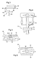
- the figure 1 presents a helicopter rotor 1.
- This rotor 1 is provided with a first and a second blade 10, 20 provided respectively with a first and a second fastening means 11, 21 to the hub 2 of the rotor 1.
- the fastening means 11, 21 are fixed to the hub 2 by usual means not shown, via laminated spherical abutments for example, allowing, among other things, each blade 10, 20 to pivot about its first longitudinal axis 13, 23.
- the blades 10, 20 are secured to their fastening means 11, 21 by pins 18. Nevertheless, the fastening means may be integral with the blades without departing from the scope of the invention.
- first and second lift elements 12, 22 are respectively mechanically connected to the first and second blades 10, 20 via first and second mechanical links 14, 24. More precisely, the first and second lift elements 12, 22 are respectively linked to the fixing means 11, 21 of the attachment zone 200 of the first and second blades 10, 20.
- Each mechanical connection 14, 24 is provided with an angle 15, 25 bent secured by its first end EX1, EX1 'to a blade 10, 20 and its second end EX2, EX2' to a hinge 16, 26 of the element lift 12, 22 associated with said blade 10, 20.
- this hinge 16, 26 the lift element is adapted to perform a rotary movement around its second longitudinal axis 17, 27 of pitch variation.
- a first end EX1 of the first angle 15 is then secured to the first fastening means 11, by screws not shown for example, while the second end EX2 of this first angle 15 is integral with the lift element 12 in rotation around the beat axis 302 of this lift element 12 being connected to a first articulation 16 of the first lift element 12.
- the first articulation 16 then allows the first lift element 12 to rotate about its second longitudinal axis 17 of step variation.
- a first end EX1 'of the second angle 25 is secured to the second fastening means 21 while the second end EX2' of this second angle 25 is integral with the lift element 22 in rotation about the beat axis of this lift element 22 being connected to a second hinge 26 of the second lift element 22.
- the second hinge 26 thus allows the second lift element 22 to rotate about its second longitudinal axis 27 of pitch variation.
- the first and second joints 16, 26 could thus be secured to the second ends EX2, EX2 'of the first and second angles 15, 25 as shown in FIG. figure 10 .
- the first hinge 16 of the first lift element 12 is then provided with a support means 300 and a fastener with three degrees of freedom 301, a spherical abutment for example.
- the support means 300 passes right through the first angle 15, passing through an orifice 303 formed in this second end EX2, before reaching the fastener with three degrees of freedom 301 secured to the hub 2.
- the three degree of freedom clip 301 is dimensioned to minimize the distance separating the beat axis 302 from the first lift member 12 to the first longitudinal pitch axis 13 of the corresponding first blade 10 so that said beat axis 302 and said first longitudinal axis 13 are substantially merged.
- a lift element is mechanically linked to a single blade.
- the pilot of the helicopter then adjusts the lift generated by the lift elements 12, 22 to make them beat.
- each lift element is integral in rotation with a first longitudinal axis 13, 23 of pitch variation of the blade 10, 20 to which it is connected.
- the first lift element 12 beats, it rotates about the first longitudinal axis 13 of the first blade 10.
- This lift element 12 being mechanically connected to the first attachment means 11 of the first blade 10, this first blade realizes at its rotational movement about the first longitudinal axis 13.
- the pitch of the first blade 10 is thus modified.
- the second lift member 22 beats, it starts a rotation around the first longitudinal axis 23 of the second blade 20 and drives with it the second blade 20 so as to change its pitch.
- the pilot controls the pitch of these lift elements, using conventional controls not shown in the figures, so as to rotate the lift element 12 , 22 concerned about its second longitudinal axis 17, 27 of variation of pitch.
- the rotor 1 comprises a main link 40 per lift element for controlling the pitch of this lift element.
- Each main link 40 is then articulated to an anchor point 41 offset from the lift element, more precisely a point remote from the support means 300 of the articulation 16.
- the anchor point 41 is said to be “offset” in the where it is not on the second longitudinal axis 17.
- the rotor 1 is equipped with a swashplate 50.
- This swashplate 50 has a non-rotating plate 52 connected to a non-rotating zone of the helicopter by a compass 53. If the non-rotating plate 52 is not rotated by the power plant of the helicopter, it can nevertheless be inclined relative to the mast 5 of the rotor 1, through a ball joint, via servo unrepresented and activated by the pilot.
- the swashplate 50 is provided with a turntable 51 integral in rotation with the mast 5. Note that the swashplate 50 is of a conventional type known to those skilled in the art.
- the main links 40 are according to this first embodiment articulated on the one hand on the anchor point 41 of the associated lift element, and on the other hand on the turntable 51 which drives them in rotation.
- anchor point 41 is, according to this first embodiment, deported using an offset 42 substantially orthogonal to the direction Z according to which the mast 5 is directed.
- the rotor 1 further comprises a return means 60, L-shaped, by lift element.
- Each return means 60 provided with a first and a second limb 61, 62 perpendicular to each other, is fixed on the hub 2 of the rotor 1 by a rod 63 at the junction of the first and second branches 61, 62 Each return means 60 is then free to perform a rotary movement around its rod 63.
- Each main link 40 is articulated on the anchoring point 41 of the associated lift element and on the first branch 61 of a return means 60.
- the main link 40 is thus substantially horizontal, in the helicopter coordinate system, and parallel to the second branch 62.
- the anchor point 41 is offset with an offset 42 substantially parallel to the direction Z in which the mast 5 is directed.
- the offset 42 is then substantially contained in a vertical plane containing the second longitudinal axis 17 of variation of pitch of the lift element 10.
- the rotor 1 comprises a secondary link 64 articulated on the one hand on the second branch 62 and on the other hand, the turntable 51.
- the secondary link is then substantially vertical, in the helicopter coordinate system, and parallel to the first branch 61.
- the turntable 51 tilts and echoes its movement to the secondary link 64.
- This secondary link 64 exerts a force on the second branch 62 of the deflection means 60 which rotates about its rod 63.
- main link 40 is then pushed or pulled as the case which allows to change the pitch of the lift element.
- the first branch 61 on which is articulated the main link 40 represents the branch of the return means 60 closest to the fuselage of the helicopter.
- the main link 40 is then fixed on the outer face F2 of the return means directed towards the lift element, while the secondary link 64 is fixed on the inner face F1 of this deflection means 60 facing the hub 2.
- the first branch 61 on which is articulated the main link 40 represents the branch of the deflection means 60 farthest from the fuselage of the helicopter.
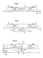
- the figure 4 presents a third embodiment of the invention.
- Each main link 40 is secured to an actuator 70, possibly piezoelectric type, able to pull or push.
- Each actuator 70 is fixed for example to the mast 5 of the rotor by a flange provided for this purpose.
- the helicopter comprises an electrical collector 71, of a known type, provided with a non-rotating element 72 and a rotating element 73 equipped with brushes, or equivalent, allowing the circulation of an electric current.
- the rotating element 73 of the electrical collector 71 is then connected by an electric cable 75 to the actuator 70, the non-rotating element 72 being connected by an electric cable 74 to a power supply source of the helicopter, and possibly especially at the controls of the pilot.
- the pilot can order the retraction or extension of the actuator to vary the pitch of the associated lift element.
- the helicopter is advantageously equipped with a stop means 30 levator elements to limit their beat.
- This abutment means 30 comprises an upper plate 31 which partially or completely overlaps the hub 2 of the rotor 1.
- the upper plate 31 is therefore facing the upper part 3 of the hub 2 furthest from the fuselage of the helicopter.
- the stop means 30 is also provided with a stroke limiter 32, a jack for example, for each lift element.
- Each stroke limiter 32 is then fixed on the upper plate 31 and on the second end EX2, EX2 'of the bracket 15, 25 corresponding to the lift element 12 associated.
- the predetermined stroke of the stroke limiter thus advantageously limits the flapping of the lift element 12.
- the stop means 30 comprises not a race limiter but a lower plate 33 opposite the lower portion 4 of the hub 2 closest to the fuselage of the helicopter.
- the upper and lower plates 31, 33 protrude from the hub 2.
- the flap of the blade exceeds a certain threshold, the second end EX2, EX2 'of the bracket 15, 25 corresponding to the lift element comes into contact with the upper plate 31, or the lower plate 33, which stops its movement.
- Damping elements an elastomer abutment for example, can be arranged on the top 31 and lower 33 plates so that the joint is not damaged by the shock resulting from the contact.
- the blades 10, 20 are all contained in a first plane P1 when they do not beat.
- the first plane P1 thus contains the first longitudinal axes 13, 23 of pitch variation of the blades 10, 20.
- the sustaining elements are all contained in a single plane P2.
- the second plane P2 contains the second longitudinal axes 17, 27 of variation of pitch of the lift elements 12, 22.
- the first and second planes P1 and P2 are merged.
- first and second planes P1, P2 are offset relative to each other, the first plane P1 being located slightly above the second plane P2.
- the shift E1 existing between the first and second planes P1, P2 is of the order of the thickness of the lift element.
- an intermediate link 100 is arranged between the second end EX2 of each bracket and the hinge 16 of the associated lift element 12.
- lift element 12 drawn on the Figures 8 and 9 is preferably supported by the hinge 16 of the lift element 12 being further fixed to the mast of the rotor for example.
- the figures describe a rotor having two blades and consequently two lift elements.
- the invention is adaptable to a helicopter with a larger number of blades without any difficulty.
- Figures 1 and 2 show that the bracket mechanically connecting a lift element to a corresponding blade is fixed by its first end to the fixing means of said blade.
- this first end of the angle can be secured not to the fastening means but to the blade itself, to a foot section of the blade for example, especially since the fastening means can be integrated in this blade.
- the angle is fixed to the attachment zone 200 of the blade to the rotor hub shown in FIG. figure 1 .
Landscapes
- Engineering & Computer Science (AREA)
- Mechanical Engineering (AREA)
- Aviation & Aerospace Engineering (AREA)
- Toys (AREA)
Claims (21)
- Helikopter mit einem Hauptrotor (1), der mindestens zwei Rotorblätter (10, 20) aufweist, wobei jedes Rotorblatt (10, 20) mit einem Mittel (11, 21) zur Befestigung an einer Nabe (2) des Rotors (1) versehen ist,
dadurch gekennzeichnet, dass der Hauptrotor (1) mit einem Auftriebselement (12, 22) pro Rotorblatt (10, 20) versehen ist, wobei jedes Auftriebselement (12, 22) mechanisch mit einem einzigen Rotorblatt (10, 20) verbunden ist, um den Anstellwinkel dieses einzigen Rotorblatts (10, 20) zu verändern, wobei jedes Auftriebselement (12, 22) drehfest bezüglich einer ersten Längsachse (13, 23) zur Veränderung des Anstellwinkels des Rotorblattes (10, 20), mit dem es mechanisch verbunden ist, befestigt ist. - Helikopter nach Anspruch 1,
dadurch gekennzeichnet, dass jedes Auftriebselement (12, 22) unabhängig von der Nabe (2) des Rotors (1) mechanisch mit einem einzigen Rotorblatt (10, 20) durch eine mechanische Verbindung (14, 24) verbunden ist. - Helikopter nach einem der vorstehenden Ansprüche,
dadurch gekennzeichnet, dass bei einer mechanischen Verbindung jedes Auftriebselements (12, 22) mit einem einzigen Rotorblatt (10, 20) durch eine mechanische Verbindung (14, 24) diese mechanische Verbindung (14, 24) einen Anschlusswinkel (15, 25) aufweist, von dem ein erstes Ende (EX1) mit einem Befestigungsbereich (200) des Rotorblatts (10) fest verbunden ist, wobei das Auftriebselement (12, 22) drehfest um die Schwenkachse des Auftriebselements an einem zweiten Ende (EX2) des Anschlusswinkels (15, 25) über ein Gelenk (16, 26) verbunden ist, welches es dem Auftriebselement (12, 22) ermöglicht, eine Drehbewegung um eine zweite Längsachse (17, 27) zur Veränderung des Anstellwinkels des Auftriebselements (12, 22) auszuführen. - Helikopter nach einem der Ansprüche 1 oder 2,
dadurch gekennzeichnet, dass bei mechanischer Befestigung eines jeden Auftriebselements (12, 22) an einem einzigen Rotorblatt (10, 20) über eine mechanische Verbindung (14, 24) die mechanische Verbindung (14, 24) einen Anschlusswinkel (15, 25) aufweist, dessen eines erstes Ende (EX1) mit einem Befestigungsbereich (200) des Rotorblatts (10) fest verbunden ist und ein zweites Ende (EX2, EX2') eines jeden Anschlusswinkels (15, 25) über ein Zwischenschaltgestänge (10) an dem entsprechenden Auftriebselement (12, 22) befestigt ist, genauer gesagt an dem Gelenk (16), welches es dem Auftriebselement ermöglicht, eine Drehbewegung um eine zweite Längsachse zur Veränderung des Anstellwinkels des Auftriebselements durchzuführen. - Helikopter nach einem der Ansprüche 3 oder 4,
dadurch gekennzeichnet, dass das Gelenk (16, 26) eines jeden Auftriebselements (12, 22) mit einem Stützmittel (300) und einer Befestigung mit drei Freiheitsgraden (301) versehen ist, wobei das Stützmittel (300) an dem entsprechenden Auf triebselement befestigt ist und die Befestigung mit drei Freiheitsgraden (301) an einer sich drehenden Einheit befestigt ist, die die Rotorwelle und die Nabe dieses Rotors sowie das Befestigungsmittel (11, 21) des Rotorblatts (10, 20) an der Nabe des Rotors umfasst. - Helikopter nach einem der Ansprüche 3 bis 5,
dadurch gekennzeichnet, dass der Befestigungsbereich (200) das Befestigungsmittel (11, 21) des Rotorblatts (10) und ein Teilstück dieses Rotorblattes umfasst, wobei das erste Ende (EX1) mit dem Befestigungsmittel (11, 21) fest verbunden ist. - Helikopter nach einem der Ansprüche 3 bis 5,
dadurch gekennzeichnet, dass, wenn der Befestigungsbereich (200) das Befestigungsmittel (11, 21) des Rotorblatts (10) und ein Teilstück dieses Rotorblattes umfasst, das erste Ende (EX1) mit dem Teilstück fest verbunden ist. - Helikopter nach einem der vorstehenden Ansprüche,
dadurch gekennzeichnet, dass, wenn die Rotorblätter (10, 20) in einer ersten Ebene (P1) liegen, während sie nicht schlagen, die Auftriebselemente (12, 22), die mechanisch mit den Rotorblättern (10, 20) verbunden sind, in einer zweiten Ebene (P2) liegen, während sie nicht schlagen, wobei die ersten und zweiten Ebenen (P1, P2) miteinander verschmolzen sind. - Helikopter nach einem der Ansprüche 1 bis 7,
dadurch gekennzeichnet, dass, wenn die Rotorblätter (10, 20) in einer ersten Ebene (P1) liegen, während sie nicht schlagen, die Auftriebselemente (12, 22), die mechanisch mit den Rotorblättern (10, 20) verbunden sind, in einer zweiten Ebene (P2) liegen, während sie nicht schlagen, wobei die ersten und zweiten Ebenen (P1, P2) parallel zueinander sind. - Helikopter nach einem der vorstehenden Ansprüche,
dadurch gekennzeichnet, dass der Rotor (1) ein Anschlagsmittel (30) aufweist, um das Schlagen eines jeden Auftriebselements (12) zu begrenzen. - Helikopter nach Anspruch 10,
dadurch gekennzeichnet, dass das Anschlagsmittel (30) mit einer oberen Platte (31) versehen ist, die mindestens teilweise einen oberen Teil (3) der Nabe (2) des Rotors (1) abdeckt, wobei der obere Bereich (3) auf der Seite der Nabe (2) gelegen ist, der dem Rumpf des Helikopters gegenüberliegt. - Helikopter nach Anspruch 11,
dadurch gekennzeichnet, dass jedes Auftriebselement (12, 22) mechanisch mit einem Rotorblatt (10, 20) über eine Aufeinanderfolge eines Gelenkes (16) und einer mechanischen Verbindung (14, 24) verbunden ist, wobei das Anschlagsmittel (30) einen Wegbegrenzer (32) pro Auftriebselement (12, 22) aufweist, und jeder Wegbegrenzer (32) zwischen der oberen Platte (31) und jedem Gelenk (16) angeordnet ist, um das Schlagen jedes Auftriebselements (12, 22) zu begrenzen. - Helikopter nach Anspruch 11,
dadurch gekennzeichnet, dass das Anschlagsmittel (30) mit einer unteren Platte (33) versehen ist, die zumindest teilweise einen unteren Teil (4) der Nabe (2) des Rotors (1) abdeckt, wobei der untere Teil (4) auf der Seiten der Nabe (2) gegenüber dem Rumpf des Helikopters gelegen ist. - Helikopter nach einem der vorstehenden Ansprüche,
gekennzeichnet durch ein Hauptschaltgestänge (40) pro Auftriebselement (12, 22), wobei jedes Hauptschaltgestänge (40) an einem versetzten Verankerungspunkt (41) eines einzigen Auftriebselements (12, 22) angelenkt ist, um den Anstellwinkel des einzigen Auftriebselements (12, 22), an dem das Hauptschaltgestänge (40) angelenkt ist, zu steuern. - Helikopter nach Anspruch 14,
dadurch gekennzeichnet, dass, wenn der Hauptrotor (1) eine Taumelscheibe (50) zur Steuerung des Anstellwinkels aufweist und mit einer sich drehenden Scheibe (51) und einer sich nicht drehenden Scheibe (52) versehen ist, jedes Hauptschaltgestänge (40) auf der sich drehenden Scheibe (51) angelenkt ist. - Helikopter nach Anspruch 14,
dadurch gekennzeichnet, dass, wenn der Hauptrotor (1) eine Taumelscheibe (50) zur Steuerung des Anstellwinkels aufweist, die mit einer sich drehenden Scheibe (51) und einer sich nicht drehenden Scheibe (52) versehen ist, das Hauptschaltgestänge (40) an einem ersten Arm (61) eines Eckumlenkungsmittels (60) angelenkt ist, welches mit der Nabe (2) des Rotors (1) fest verbunden ist, und wobei ein zweiter Arm (62) dieses Eckumlenkungsmittels (60) über ein sekundäres Schaltgestänge (64) mit der sich drehenden Scheibe (51) verbunden ist. - Helikopter nach Anspruch 16,
dadurch gekennzeichnet, dass, wenn der Helikopter ein Stellorgan (70) mit Hauptschaltgestänge (40) aufweist, jedes Hauptschaltgestänge (40) durch ein Stellorgan (70) gesteuert wird, welches elektrisch über einen elektrischen Sammler (71) gespeist wird, der auf einer sich drehenden Welle (5) des Rotors (1) angeordnet ist. - Helikopter nach Anspruch 17,
dadurch gekennzeichnet, dass, wenn der Helikopter ein Stellorgan (70) mit Hauptschaltgestänge (40) aufweist, jedes Hauptschaltgestänge (40) durch ein Stellorgan (70) gesteuert wird, welches elektrisch über einen Stromgenerator gespeist wird, der einen Stator aufweist, der im Inneren einer sich drehenden Welle (5) des Rotors (1) angeordnet ist, wobei ein sich drehendes Organ des Generators fest mit der Welle (5) verbunden ist. - Helikopter nach einem der Ansprüche 17 oder 18,
dadurch gekennzeichnet, dass das Stellorgan (70) durch ein drahtloses Übertragungsmittel gesteuert wird. - Helikopter nach einem der vorstehenden Ansprüche, dadurch gekennzeichnet, dass jedes Auftriebselement (12, 22) funktionell und mechanisch unabhängig gesteuert wird, derart, dass der Anstellwinkel eines einzelnen Rotorblattes individuell verstellt werden kann.
- Verfahren zum Verstellen des Anstellwinkels eines Rotorblatts (10, 20) eines Rotors eines Helikopters, der mindestens zwei Rotorblätter aufweist,
dadurch gekennzeichnet, dass bei einem Auftriebselement (12, 22), welches ausschließlich mit dem Rotorblatt (10, 20) verbunden ist, der von dem Auftriebselement (12, 22) erzeugte Auftrieb eingestellt wird, um zu bewirken, dass dieses Auf triebselement (12, 22) schlägt, um das Rotorblatt (10, 20), mit welchem es verbunden ist, zu einer Drehung um eine erste Längsachse (13, 23) zur Verstellung des Anstellwinkels dieses Rotorblatts (10, 20) anzutreiben, wobei der Auftrieb des Auftriebselements (12, 22) eingestellt wird, indem der Anstellwinkel des Auftriebselements (12, 22) verändert wird, und somit das Auftriebselement (12, 22) in eine Drehbewegung um eine zweite Längsachse (17, 27) versetzt wird zur Veränderung des Anstellwinkels des Auftriebselements (12, 22).
Priority Applications (1)
| Application Number | Priority Date | Filing Date | Title |
|---|---|---|---|
| PL09002430T PL2096031T3 (pl) | 2008-02-27 | 2009-02-20 | Śmigłowiec wyposażony w wiele elementów nośnych do sterowania kątem natarcia jego łopat |
Applications Claiming Priority (1)
| Application Number | Priority Date | Filing Date | Title |
|---|---|---|---|
| FR0801079A FR2927881B1 (fr) | 2008-02-27 | 2008-02-27 | Helicoptere muni d'une pluralite d'elements sustentateurs pour commander l'incidence de ses pales |
Publications (2)
| Publication Number | Publication Date |
|---|---|
| EP2096031A1 EP2096031A1 (de) | 2009-09-02 |
| EP2096031B1 true EP2096031B1 (de) | 2012-04-18 |
Family
ID=39816840
Family Applications (1)
| Application Number | Title | Priority Date | Filing Date |
|---|---|---|---|
| EP09002430A Active EP2096031B1 (de) | 2008-02-27 | 2009-02-20 | Hubschrauber, der mit einer Vielzahl von Auftriebselementen zur Steuerung des Einfallwinkels seiner Blätter ausgestattet ist |
Country Status (6)
| Country | Link |
|---|---|
| US (1) | US8177508B2 (de) |
| EP (1) | EP2096031B1 (de) |
| CN (1) | CN101519123B (de) |
| CA (1) | CA2655894C (de) |
| FR (1) | FR2927881B1 (de) |
| PL (1) | PL2096031T3 (de) |
Families Citing this family (19)
| Publication number | Priority date | Publication date | Assignee | Title |
|---|---|---|---|---|
| NO330820B1 (no) * | 2009-12-24 | 2011-07-25 | Prox Dynamics As | Rotormekanisme for helikoptere |
| CN102081353B (zh) * | 2010-06-28 | 2012-10-31 | 南京航空航天大学 | 电控旋翼桨距自适应控制方法 |
| CN101927831B (zh) * | 2010-07-28 | 2012-12-19 | 北京航空航天大学 | 一种基于变桨矩发动机配置的无人机遥控链路中断处理方法 |
| CN102069907A (zh) * | 2010-09-16 | 2011-05-25 | 孙为红 | 旋翼机旋翼角度固定装置 |
| CN102285450A (zh) * | 2011-06-08 | 2011-12-21 | 中北大学 | 变桨距三轴飞行器 |
| CN102390527B (zh) * | 2011-09-06 | 2015-02-04 | 陈仁多 | 一种直升机旋翼活动系统改进设计 |
| FR2982584B1 (fr) | 2011-11-10 | 2014-03-21 | Eurocopter France | Dispositif de variation de pas des pales d'un rotor de sustentation |
| EP2818407B1 (de) * | 2013-06-24 | 2016-12-21 | AIRBUS HELICOPTERS DEUTSCHLAND GmbH | Rotorsystem eines Hubschraubers |
| CN103407571B (zh) * | 2013-07-15 | 2015-09-09 | 南京航空航天大学 | 一种可主动摆振的直升机旋翼系统 |
| US9315265B2 (en) * | 2013-07-29 | 2016-04-19 | Sikorsky Aircraft Corporation | Adjustable scissor control link |
| US9796469B2 (en) * | 2014-04-04 | 2017-10-24 | The Boeing Company | Modular rotor craft rotor hub system |
| US20160090178A1 (en) * | 2014-09-29 | 2016-03-31 | Blair John Paynton | Leverage Pitch Link |
| US9957041B2 (en) * | 2015-05-21 | 2018-05-01 | Merlin Technology, Inc. | Advanced emergency collective actuator with friction pull-off and method for a helicopter |
| CN105292465B (zh) * | 2015-11-04 | 2017-05-03 | 中航维拓(北京)科技有限责任公司 | 一种直升机的刚性旋翼系统 |
| EP3225543B1 (de) * | 2016-04-01 | 2018-11-14 | AIRBUS HELICOPTERS DEUTSCHLAND GmbH | Vortriebseinrichtung mit mindestens zwei propellerschaufeln |
| US10994840B1 (en) | 2017-08-16 | 2021-05-04 | United States Of America As Represented By The Secretary Of The Air Force | Thrust vectoring control of a cyclorotor |
| WO2022133132A2 (en) * | 2020-12-16 | 2022-06-23 | Dash Systems, Inc. | Autorotating payload delivery device |
| CN112623211B (zh) * | 2020-12-28 | 2022-09-06 | 桂林航天工业学院 | 一种测绘航拍用的无人机 |
| CN120024492B (zh) * | 2025-03-24 | 2026-01-06 | 中国航天科工集团第二研究院 | 一种采用翼梢阵列涵道风扇驱动旋翼的垂直起降飞行器 |
Family Cites Families (9)
| Publication number | Priority date | Publication date | Assignee | Title |
|---|---|---|---|---|
| US2457429A (en) * | 1945-05-09 | 1948-12-28 | Bell Aircraft Corp | Rotary wing aircraft |
| US2481750A (en) * | 1947-06-03 | 1949-09-13 | United Helicopters Inc | Helicopter |
| US2534353A (en) * | 1949-01-24 | 1950-12-19 | United Helicopters Inc | Rotary wing aircraft |
| GB735571A (en) * | 1951-06-25 | 1955-08-24 | Hiller Helicopters | Rotor head for rotary wing aircraft |
| US2818123A (en) * | 1955-06-23 | 1957-12-31 | Hiller Helicopters | Rotary wing aircraft |
| DE2409227A1 (de) * | 1974-02-27 | 1975-09-04 | Schlueter Dieter | Hauptrotor fuer einen hubschrauber |
| CN1472113A (zh) * | 2002-08-02 | 2004-02-04 | 洪 章 | 新型旋翼飞行器 |
| CN2776504Y (zh) * | 2005-01-31 | 2006-05-03 | 杨克伟 | 一种直升机螺旋桨操纵装置 |
| CN100415602C (zh) * | 2005-06-29 | 2008-09-03 | 上海大学 | 非对称桨叶变距装置 |
-
2008
- 2008-02-27 FR FR0801079A patent/FR2927881B1/fr not_active Expired - Fee Related
-
2009
- 2009-02-20 EP EP09002430A patent/EP2096031B1/de active Active
- 2009-02-20 PL PL09002430T patent/PL2096031T3/pl unknown
- 2009-02-25 US US12/392,426 patent/US8177508B2/en not_active Expired - Fee Related
- 2009-02-25 CA CA2655894A patent/CA2655894C/fr active Active
- 2009-02-27 CN CN200910008393XA patent/CN101519123B/zh not_active Expired - Fee Related
Also Published As
| Publication number | Publication date |
|---|---|
| FR2927881B1 (fr) | 2010-10-29 |
| CN101519123B (zh) | 2011-11-16 |
| CA2655894C (fr) | 2012-05-15 |
| CA2655894A1 (fr) | 2009-08-27 |
| EP2096031A1 (de) | 2009-09-02 |
| US20090214340A1 (en) | 2009-08-27 |
| FR2927881A1 (fr) | 2009-08-28 |
| CN101519123A (zh) | 2009-09-02 |
| PL2096031T3 (pl) | 2012-09-28 |
| US8177508B2 (en) | 2012-05-15 |
Similar Documents
| Publication | Publication Date | Title |
|---|---|---|
| EP2096031B1 (de) | Hubschrauber, der mit einer Vielzahl von Auftriebselementen zur Steuerung des Einfallwinkels seiner Blätter ausgestattet ist | |
| EP2096030B1 (de) | Hubschrauber, der mit einer Vielzahl von Auftriebselementen ausgestattet ist und über eine Klappe zur Steuerung des Einfallwinkels seiner Blätter verfügt | |
| EP2407377B1 (de) | Verfahren und Luftfahrzeug, das mit einem Heck-Kipprotor ausgestattet ist | |
| EP3118112B1 (de) | Kombiniertes luftfahrzeug, das mit einer zusätzlichen gegendrehmomentvorrichtung ausgestattet ist | |
| EP2886459B1 (de) | Drehflügelflugzeug, das mit einer Heckrotorkonfiguration ausgestattet ist, die selektiv an der Auftriebs- und Translationsbewegung des Drehflügelflugzeugs beteiligt ist | |
| EP3328732B1 (de) | Auftriebsrotor und hybridluftfahrzeug mit vertikalem oder kurzem start und/oder landung | |
| EP2511176B1 (de) | Drehflügelblatt, Rotor, der mindestens zwei solcher Blätter umfasst, und Verfahren zum Einsatz eines solchen Rotors | |
| FR2600036A1 (fr) | Dispositif directionnel et stabilisateur a rotor anti-couple carene et incline et a empennage en " v " dissymetrique, et helicoptere equipe d'un tel dispositif. | |
| WO2012130856A1 (fr) | Micro/nano véhicule aérien commande à distance comportant un système de roulage au sol, de décollage vertical et d'atterrissage | |
| EP3025959B1 (de) | Heckrotor eines drehflügelflugzeugs, drehflügelflugzeug, das mit einem solchen heckrotor ausgestattet ist und statisches und/oder dynamisches auswuchten eines heckrotors eines drehflügelflugzeugs | |
| FR2804082A1 (fr) | Aeronef a ailes tournantes | |
| EP2708466B1 (de) | Nickstabilisierungsmittel und Drehflügler mit solchen Mitteln | |
| WO2012076705A2 (fr) | Rotor d'aéronef à ailes rotatives | |
| FR2801034A1 (fr) | Helicoptere a pilotage pendulaire a haute stabilite et a grande manoeuvrabilite | |
| FR3078945A1 (fr) | Aerodyne hybride de type vtol ou stol (basculement rotor) | |
| EP2530013B1 (de) | Rotorblattverdrehmechanismus für Drehflügelflugzeug, und Blatt | |
| FR2648106A1 (fr) | Dispositif de butees escamotables pour pales de rotors de giravions, et tete de rotor le comportant | |
| EP0318477B1 (de) | Senkrechtstarter | |
| EP3765362B1 (de) | Hybrider aerodyn vom vtol- oder stol-typ (rotorverkeilung) | |
| FR2758525A1 (fr) | Rotor a pales repliables, pour voilure tournante d'aeronef | |
| FR2552395A1 (fr) | Perfectionnements apportes aux helices sustentatrices pour aeronefs | |
| FR2946619A1 (fr) | Dispositif d'orientation des derives pour helicoptere a rotors contrarotatifs | |
| FR2909638A1 (fr) | Systeme de modification du centrage en vol pour engin volant pilote du type pendulaire. |
Legal Events
| Date | Code | Title | Description |
|---|---|---|---|
| PUAI | Public reference made under article 153(3) epc to a published international application that has entered the european phase |
Free format text: ORIGINAL CODE: 0009012 |
|
| AK | Designated contracting states |
Kind code of ref document: A1 Designated state(s): AT BE BG CH CY CZ DE DK EE ES FI FR GB GR HR HU IE IS IT LI LT LU LV MC MK MT NL NO PL PT RO SE SI SK TR |
|
| AX | Request for extension of the european patent |
Extension state: AL BA RS |
|
| 17P | Request for examination filed |
Effective date: 20100201 |
|
| AKX | Designation fees paid |
Designated state(s): DE GB IT PL |
|
| GRAP | Despatch of communication of intention to grant a patent |
Free format text: ORIGINAL CODE: EPIDOSNIGR1 |
|
| GRAS | Grant fee paid |
Free format text: ORIGINAL CODE: EPIDOSNIGR3 |
|
| GRAA | (expected) grant |
Free format text: ORIGINAL CODE: 0009210 |
|
| AK | Designated contracting states |
Kind code of ref document: B1 Designated state(s): DE GB IT PL |
|
| REG | Reference to a national code |
Ref country code: GB Ref legal event code: FG4D Free format text: NOT ENGLISH |
|
| REG | Reference to a national code |
Ref country code: DE Ref legal event code: R096 Ref document number: 602009006301 Country of ref document: DE Effective date: 20120621 |
|
| REG | Reference to a national code |
Ref country code: PL Ref legal event code: T3 |
|
| PLBE | No opposition filed within time limit |
Free format text: ORIGINAL CODE: 0009261 |
|
| STAA | Information on the status of an ep patent application or granted ep patent |
Free format text: STATUS: NO OPPOSITION FILED WITHIN TIME LIMIT |
|
| 26N | No opposition filed |
Effective date: 20130121 |
|
| REG | Reference to a national code |
Ref country code: DE Ref legal event code: R097 Ref document number: 602009006301 Country of ref document: DE Effective date: 20130121 |
|
| REG | Reference to a national code |
Ref country code: DE Ref legal event code: R082 Ref document number: 602009006301 Country of ref document: DE Representative=s name: GPI & ASSOCIES, FR |
|
| REG | Reference to a national code |
Ref country code: DE Ref legal event code: R082 Ref document number: 602009006301 Country of ref document: DE Representative=s name: GPI & ASSOCIES, FR Ref country code: DE Ref legal event code: R081 Ref document number: 602009006301 Country of ref document: DE Owner name: AIRBUS HELICOPTERS, FR Free format text: FORMER OWNER: EUROCOPTER, MARIGNANE, FR |
|
| PGFP | Annual fee paid to national office [announced via postgrant information from national office to epo] |
Ref country code: GB Payment date: 20220223 Year of fee payment: 14 Ref country code: DE Payment date: 20220217 Year of fee payment: 14 |
|
| PGFP | Annual fee paid to national office [announced via postgrant information from national office to epo] |
Ref country code: PL Payment date: 20220214 Year of fee payment: 14 |
|
| P01 | Opt-out of the competence of the unified patent court (upc) registered |
Effective date: 20230530 |
|
| REG | Reference to a national code |
Ref country code: DE Ref legal event code: R119 Ref document number: 602009006301 Country of ref document: DE |
|
| GBPC | Gb: european patent ceased through non-payment of renewal fee |
Effective date: 20230220 |
|
| PG25 | Lapsed in a contracting state [announced via postgrant information from national office to epo] |
Ref country code: GB Free format text: LAPSE BECAUSE OF NON-PAYMENT OF DUE FEES Effective date: 20230220 |
|
| PG25 | Lapsed in a contracting state [announced via postgrant information from national office to epo] |
Ref country code: GB Free format text: LAPSE BECAUSE OF NON-PAYMENT OF DUE FEES Effective date: 20230220 Ref country code: DE Free format text: LAPSE BECAUSE OF NON-PAYMENT OF DUE FEES Effective date: 20230901 |
|
| PG25 | Lapsed in a contracting state [announced via postgrant information from national office to epo] |
Ref country code: PL Free format text: LAPSE BECAUSE OF NON-PAYMENT OF DUE FEES Effective date: 20230220 |
|
| PG25 | Lapsed in a contracting state [announced via postgrant information from national office to epo] |
Ref country code: PL Free format text: LAPSE BECAUSE OF NON-PAYMENT OF DUE FEES Effective date: 20230220 |
|
| PGFP | Annual fee paid to national office [announced via postgrant information from national office to epo] |
Ref country code: IT Payment date: 20260224 Year of fee payment: 18 |