EP2096076A1 - Winding device for at least one lifting rope - Google Patents
Winding device for at least one lifting rope Download PDFInfo
- Publication number
- EP2096076A1 EP2096076A1 EP09002491A EP09002491A EP2096076A1 EP 2096076 A1 EP2096076 A1 EP 2096076A1 EP 09002491 A EP09002491 A EP 09002491A EP 09002491 A EP09002491 A EP 09002491A EP 2096076 A1 EP2096076 A1 EP 2096076A1
- Authority
- EP
- European Patent Office
- Prior art keywords
- carriage
- cable
- winding device
- winding
- rope
- Prior art date
- Legal status (The legal status is an assumption and is not a legal conclusion. Google has not performed a legal analysis and makes no representation as to the accuracy of the status listed.)
- Granted
Links
- 238000004804 winding Methods 0.000 title claims abstract description 36
- 239000002356 single layer Substances 0.000 claims abstract description 13
- 230000008878 coupling Effects 0.000 claims 3
- 238000010168 coupling process Methods 0.000 claims 3
- 238000005859 coupling reaction Methods 0.000 claims 3
- 230000005540 biological transmission Effects 0.000 claims 1
- 230000001360 synchronised effect Effects 0.000 abstract description 2
- 238000009434 installation Methods 0.000 description 2
- 239000000463 material Substances 0.000 description 2
- 239000013585 weight reducing agent Substances 0.000 description 2
- 229910000831 Steel Inorganic materials 0.000 description 1
- 238000011161 development Methods 0.000 description 1
- 230000018109 developmental process Effects 0.000 description 1
- 238000005516 engineering process Methods 0.000 description 1
- 238000000034 method Methods 0.000 description 1
- 238000012986 modification Methods 0.000 description 1
- 230000004048 modification Effects 0.000 description 1
- 230000002093 peripheral effect Effects 0.000 description 1
- 239000010959 steel Substances 0.000 description 1
Images

Classifications
-
- B—PERFORMING OPERATIONS; TRANSPORTING
- B66—HOISTING; LIFTING; HAULING
- B66D—CAPSTANS; WINCHES; TACKLES, e.g. PULLEY BLOCKS; HOISTS
- B66D1/00—Rope, cable, or chain winding mechanisms; Capstans
- B66D1/28—Other constructional details
- B66D1/36—Guiding, or otherwise ensuring winding in an orderly manner, of ropes, cables, or chains
- B66D1/39—Guiding, or otherwise ensuring winding in an orderly manner, of ropes, cables, or chains by means of axially-movable drums or barrels
-
- A—HUMAN NECESSITIES
- A63—SPORTS; GAMES; AMUSEMENTS
- A63J—DEVICES FOR THEATRES, CIRCUSES, OR THE LIKE; CONJURING APPLIANCES OR THE LIKE
- A63J1/00—Stage arrangements
- A63J1/02—Scenery; Curtains; Other decorations; Means for moving same
- A63J1/028—Means for moving hanging scenery
-
- B—PERFORMING OPERATIONS; TRANSPORTING
- B66—HOISTING; LIFTING; HAULING
- B66D—CAPSTANS; WINCHES; TACKLES, e.g. PULLEY BLOCKS; HOISTS
- B66D1/00—Rope, cable, or chain winding mechanisms; Capstans
- B66D1/26—Rope, cable, or chain winding mechanisms; Capstans having several drums or barrels
Definitions
- the invention relates to a winding device according to the preamble of claim 1.
- Et al in the stage technique e.g. for theater stages winding devices are known, with which trains or hoisting ropes motorized on cable drums and are handled, for example, hoisting ropes for stage elements, such as scenes, but also for raising or lowering people, etc.
- the object of the invention is to show a winding device that fully meets these requirements and allows a space-saving installation.
- the winding device provides the compulsorily ordered single-layer winding of the respective cable or hoist rope on the associated cable drum and compliance with the cable running angle within predetermined limits thereby ensures that the at least one cable drum having carriage is moved synchronously with the rotational movement with the cable drum in the axial direction, namely, the slope of the single-layer winding accordingly, and that also the rope of the cable drum when winding and unwinding radially tapers, for example via a not moving with the carriage pulley.
- the lifting movement of the carriage is a vertical lifting movement, so that there is the possibility of extremely space-saving installation of the winding device, which is particularly important for use in the stage technology of great importance.
- the weight of the carriage is compensated or at least compensated so far that the vertical movement of the carriage only small forces are required, i. for the vertical lifting movement only a low-loaded lifting drive is sufficient.
- This can be designed for example as a low-loaded spindle drive.
- the lifting drive is realized in a particularly simple manner in that at least one driver not moved along with the carriage engages in the cable groove formed on the at least one cable drum and encloses the axis of this cable drum in a spiral manner for the hoisting cable to be wound up and unwound.
- winch or winding device consists essentially of a guided on a vertical guide 2 carriages 3, on which a shaft 4 is rotatably mounted at both ends, in such a way that this shaft 4 is oriented with its axis in the vertical direction and thus parallel to the guide 2.
- a shaft 4 is rotatably mounted at both ends, in such a way that this shaft 4 is oriented with its axis in the vertical direction and thus parallel to the guide 2.
- three cable drums 5, 6 and 7 are provided, in each case for the single-layer winding of a hoisting cable 8.
- the three hoisting ropes 8 are in the illustrated embodiment, three in the Figures 1 and 2 coaxially arranged one behind the other upper guide rollers 9, over which the first horizontally extending hoisting ropes 8 are deflected vertically. Each hoist rope 8 is then guided over a further deflection roller 10, so that it runs horizontally or substantially horizontally of the associated cable drum 5-7. Since the cable drum 5-7 on the common shaft 4 in the axial direction of this shaft, that are provided offset from one another in the vertical direction, the guide rollers 10 are arranged offset from each other in the vertical direction. All pulleys 10 are oriented with their horizontal axes parallel to each other on the guide 2 and freely rotatably supported there provided bearings.
- a compensation device 12 which consists in the illustrated embodiment essentially of a double-armed pivot lever 13 which is held between its two ends 13.1 and 13.2 about a horizontal axis 14 parallel to the axes of the guide rollers 9 and 10 pivotally mounted on the vertical guide 2 and with the roller 15 provided with a lever arm 13.1 forms a support for the underside of the carriage 3 and with its other end or lever arm 13.2 is connected to at least one gas spring 16 which acts between this end of the lever 13 and the vertical guide 2.
- the roller 15 is provided on the underside of the carriage 3 a merging with this roller sliding guide 15.1.
- the weight compensation device 12 is adjusted so that the total weight of the carriage 3 and provided on this slide functional elements is compensated or largely compensated.
- the weight relief of the weight compensation device 12 is adjustable, in the illustrated embodiment in that the point of application of the gas spring 16 on the lever arm 13.2 is radially adjustable to the pivot point 14, like this in the Figures 1 and 2 is indicated by the local slot 13.2.1.
- a simple spindle drive for example using a threaded spindle 17, which is also at both ends of the carriage is rotatably supported, with its axis in the vertical direction and thus oriented parallel to the shaft 4 and the guide 2 and is driven by the drive 11.
- the spindle 17 cooperates with a nut threaded piece, which is provided on the guide 2 or on a projecting beyond the guide 2 supporting arm 18.
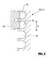
- FIG. 3 shows again in a very simplified partial representation of the cable drums 5, 6 and 7.
- each cable drum is provided on its peripheral surface with a cable groove 19 which extends helically around the axis of the cable drum 5, 6 and 7 respectively and for single-layer recording of the relevant hoist rope 8 is formed.
- FIG. 3 shows a in the rope grooves 19 of a cable drum 5, 6 and 7 engaging driver 20 which is not moved along the guide 2 with the carriage 3, so that upon rotation of the shaft 4 via this engaging in the spiral cable groove 19 driver 20, the lifting movement of the carriage 3 in the single-layer winding of the hoisting ropes 8 on the cable drums 5, 6 and 7 or in the local cable grooves 19 and the unwinding of the hoisting ropes 8 of the cable drums 5 - 7 is generated.
- the driver 20 is preferably made of a material which is much softer compared to the material of the cable drum (for example steel), for example of plastic. This is possible by the weight reduction of the carriage 3 by the weight compensation device 12.
- the weight compensation device 12 consists of a lever 13 and a gas spring 16.
- a weight reduction can also take place by means of, for example, a balance weight or at least one compensating spring element having a relief cable.
Landscapes
- Engineering & Computer Science (AREA)
- Mechanical Engineering (AREA)
- Types And Forms Of Lifts (AREA)
Abstract
Description
Die Erfindung bezieht sich auf eine Wickelvorrichtung gemäß Oberbegriff Patentanspruch 1.The invention relates to a winding device according to the preamble of
U.a. in der Bühnentechnik, z.B. für Theaterbühnen sind Wickelvorrichtungen bekannt, mit denen Züge oder Hubseile motorisch auf Seiltrommeln auf- und abgewickelt werden, und zwar beispielsweise Hubseile für Bühnenelemente, wie Kulissen, aber auch zum Anheben oder Absenken von Personen usw.Et al in the stage technique, e.g. for theater stages winding devices are known, with which trains or hoisting ropes motorized on cable drums and are handled, for example, hoisting ropes for stage elements, such as scenes, but also for raising or lowering people, etc.
Allein schon aus Sicherheitsgründen ist es bei Wickelvorrichtungen oder Seilwinden vielfach gefordert, dass das Aufwickeln des jeweiligen Seils oder Hubseiles auf die zugehörige Wickeltrommel als zwangsweise geordnete einlagige Wicklung erfolgt, und zwar unter Einhaltung eines Seillaufwinkels innerhalb bestimmter Grenzen. Aufgabe der Erfindung ist es, eine Wickelvorrichtung aufzuzeigen, die diesen Erfordernissen voll gerecht wird und eine platzsparende Aufstellung ermöglicht.Already for safety reasons, it is often required in winding devices or winches that the winding of the respective rope or hoisting rope on the associated winding drum as compulsorily ordered single-layer winding is done, while maintaining a cable running angle within certain limits. The object of the invention is to show a winding device that fully meets these requirements and allows a space-saving installation.
Zur Lösung dieser Aufgabe ist eine Wickelvorrichtung entsprechend dem Patentanspruch 1 ausgebildet.To solve this problem, a winding device according to the
Die erfindungsgemäße Wickelvorrichtung stellt das zwangsweise geordnete einlagige Aufwickeln des jeweiligen Seils oder Hubseiles auf die zugehörige Seiltrommel und die Einhaltung des Seillaufwinkels innerhalb vorgegebener Grenzen dadurch sichert, dass der die wenigstens eine Seiltrommel aufweisende Schlitten synchron mit der Drehbewegung mit der Seiltrommel in deren Achsrichtung bewegt wird, und zwar der Steigung der einlagigen Wicklung entsprechend, und dass außerdem das Seil der Seiltrommel beim Auf- und Abwickeln radial zuläuft, und zwar beispielsweise über eine sich mit dem Schlitten nicht mitbewegende Umlenkrolle. Die Hubbewegung des Schlittens ist dabei eine vertikale Hubbewegung, sodass sich die Möglichkeit einer äußerst platzsparenden Aufstellung der Wickelvorrichtung ergibt, was insbesondere auch für den Einsatz in der Bühnentechnik von großer Bedeutung ist.The winding device according to the invention provides the compulsorily ordered single-layer winding of the respective cable or hoist rope on the associated cable drum and compliance with the cable running angle within predetermined limits thereby ensures that the at least one cable drum having carriage is moved synchronously with the rotational movement with the cable drum in the axial direction, namely, the slope of the single-layer winding accordingly, and that also the rope of the cable drum when winding and unwinding radially tapers, for example via a not moving with the carriage pulley. The lifting movement of the carriage is a vertical lifting movement, so that there is the possibility of extremely space-saving installation of the winding device, which is particularly important for use in the stage technology of great importance.
Durch eine Gewichtsentlastungseinrichtung ist das Gewicht des Schlittens, einschließlich sämtlicher an diesem Schlitten vorgesehener Elemente kompensiert oder zumindest aber soweit kompensiert, dass für die vertikale Bewegung des Schlittens nur geringe Kräfte erforderlich sind, d.h. für die vertikale Hubbewegung ein nur niedrig belasteter Hubantrieb ausreicht. Dieser kann beispielsweise als niedrig belasteter Spindelantrieb ausgebildet sein.By a weight relief device, the weight of the carriage, including all provided on this slide elements is compensated or at least compensated so far that the vertical movement of the carriage only small forces are required, i. for the vertical lifting movement only a low-loaded lifting drive is sufficient. This can be designed for example as a low-loaded spindle drive.
Bei einer bevorzugten Ausführungsform der Erfindung ist der Hubantrieb in besonders einfacher Weise dadurch realisiert, dass wenigstens ein mit dem Schlitten nicht mitbewegter Mitnehmer in die an der wenigstens einen Seiltrommel ausgebildete, die Achse dieser Seiltrommel wendelartig umschließenden Seilnut für das auf- und abzuwickelnde Hubseil eingreift.In a preferred embodiment of the invention, the lifting drive is realized in a particularly simple manner in that at least one driver not moved along with the carriage engages in the cable groove formed on the at least one cable drum and encloses the axis of this cable drum in a spiral manner for the hoisting cable to be wound up and unwound.
Weiterbildungen, Vorteile und Anwendungsmöglichkeiten der Erfindung ergeben sich auch aus der nachfolgenden Beschreibung von Ausführungsbeispielen und aus den Figuren. Dabei sind alle beschriebenen und/oder bildlich dargestellten Merkmale für sich oder in beliebiger Kombination grundsätzlich Gegenstand der Erfindung, unabhängig von ihrer Zusammenfassung in den Ansprüchen oder deren Rückbeziehung. Auch wird der Inhalt der Ansprüche zu einem Bestandteil der Beschreibung gemacht.Further developments, advantages and applications of the invention will become apparent from the following description of exemplary embodiments and from the figures. In this case, all described and / or illustrated features alone or in any combination are fundamentally the subject of the invention, regardless of their summary in the claims or their dependency. Also, the content of the claims is made an integral part of the description.
Die Erfindung wird im Folgenden anhand der Figuren an einem Ausführungsbeispiel näher erläutert. Es zeigen:
- Fig. 1 und 2
- jeweils in vereinfachter Darstellung eine Wickelvorrichtung für Hubseile in zwei unterschiedlichen Betriebszuständen;
- Fig. 3
- in vereinfachter schematischer Darstellung eine der Seiltrommeln der Vorrichtung der
Figuren 1 und 2
- Fig. 1 and 2
- each in a simplified representation of a winding device for hoisting ropes in two different operating conditions;
- Fig. 3
- in a simplified schematic representation of the cable drums of the device
Figures 1 and 2 together with an element of the device which meshes with a cable groove.
Die in den Figuren allgemein mit 1 bezeichnete Seilwinde bzw. Wickelvorrichtung besteht im Wesentlichen aus einem an einer vertikalen Führung 2 geführten Schlitten 3, auf welchem eine Welle 4 beidendig drehbar gelagert ist, und zwar derart, dass diese Welle 4 mit ihrer Achse in vertikaler Richtung und damit parallel zur Führung 2 orientiert ist. Auf der Welle 4 sind drei Seiltrommeln 5, 6 und 7 vorgesehen, und zwar jeweils zum einlagigen Aufwickeln eines Hubseils 8.The generally designated 1 in the figures winch or winding device consists essentially of a guided on a
Die drei Hubseile 8 sind bei der dargestellten Ausführungsform über drei in den
An dem Schlitten 4 ist weiterhin der u.a. von einem Elektromotor und einem Getriebe gebildete Antrieb der Wickelvorrichtung 1 bzw. für die Welle 4 und die dortigen Seiltrommeln 5 - 7 vorgesehen. Zur Kompensation des Gesamtgewichts des Schlittens 3 einschließlich der an diesem Schlitten vorgesehenen Elemente, insbesondere auch der Welle 4 mit den Seiltrommeln 5 - 7 und des Antriebs 11, ist eine Kompensationseinrichtung 12 vorgesehen, die bei der dargestellten Ausführungsform im Wesentlichen aus einem doppelarmigen Schwenkhebel 13 besteht, der zwischen seinen beiden Enden 13.1 und 13.2 um eine horizontale Achse 14 parallel zu den Achsen der Umlenkrollen 9 und 10 schwenkbar an der vertikalen Führung 2 gehalten ist und mit dem mit einer Rolle 15 versehenen Hebelarm 13.1 eine Abstützung für die Unterseite des Schlittens 3 bildet und mit seinem anderen Ende bzw. Hebelarm 13.2 mit wenigstens einer Gasfeder 16 verbunden ist, die zwischen diesem Ende des Hebels 13 und der vertikalen Führung 2 wirkt. Für die Rolle 15 ist an der Unterseite des Schlittens 3 ein mit dieser Rolle zusammenführende Gleitführung 15.1 vorgesehen.On the carriage 4 of the further example of an electric motor and a gear drive formed the
Durch entsprechende Wahl der Gasfeder 16 und des durch den Hebel 13 bzw. dessen Hebelarme 13.1 und 13.2 bewirkten Übersetzungsverhältnis ist die Gewichtskompensationseinrichtung 12 so eingestellt, dass das gesamte Gewicht des Schlittens 3 und der an diesem Schlitten vorgesehenen Funktionselemente kompensiert bzw. weitestgehend kompensiert ist.By appropriate selection of the
Um Toleranzen der Gasfeder 16 sowie Gewichtstolleranzen des Schlittens 3 und der an diesem vorgesehenen Funktionselemente auszugleichen, ist die Gewichtsentlastung der Gewichtskompensationseinrichtung 12 einstellbar, und zwar bei der dargestellten Ausführungsform dadurch, dass der Angriffspunkt der Gasfeder 16 am Hebelarm 13.2 radial zum Schwenkpunkt 14 einstellbar ist, wie dies in den
Durch die Kompensation des Gewichtes des Schlittens 3 und der an diesem Schlitten vorgesehenen Funktionselement ist es in besonders einfacher Weise möglich, den gesamten Schlitten 3 in vertikaler Richtung an der Führung 2 auf und ab zu bewegen (Doppelpfeil A), um dadurch das erforderliche einlagige Aufwickeln der Hubseile 8 auf der jeweiligen Seiltrommel 5 bzw. 6 sowie das Abwickeln der Hubseile von diesen Seiltrommeln 5 - 7 bei mit dem Schlitten 3 nicht mitbewegten Umlenkrollen 10 zu erreichen. Die für das einlagige bzw. gewendelte Aufwickeln der Hubseile 8 auf den Seiltrommeln 5 - 7 erforderliche, mit der Drehbewegung der Welle 4 synchronisierte Bewegen des Schlittens 3 ist mit einem einfachen Spindelantrieb erreichbar, beispielsweise unter Verwendung einer Gewindespindel 17, die ebenfalls beidendig am Schlitten 3 drehbar gelagert ist, mit ihrer Achse in vertikaler Richtung und damit parallel zur Welle 4 und zur Führung 2 orientiert ist und durch den Antrieb 11 angetrieben wird. Die Spindel 17 wirkt mit einem Muttergewindestück zusammen, welches an der Führung 2 bzw. an einem über die Führung 2 wegstehenden Tragarm 18 vorgesehen ist.By compensating for the weight of the
Die
Vorstehend wurde davon ausgegangen, dass die Hubbewegung des Schlittens 3 über die nur gering belastete Gewindespindel 17 erfolgt. Die
Die Erfindung wurde voranstehend an einem Ausführungsbeispiel beschrieben. Es versteht sich, dass zahlreiche Änderungen sowie Abwandlungen möglich sind, ohne dass dadurch der der Erfindung zugrunde liegende Erfindungsgedanke verlassen wird. So wurde vorstehend davon ausgegangen, dass mit dem Schlitten 3 die gesamte Seilwinde im Wesentlichen bestehend aus der Welle 4, den dortigen Seiltrommeln 5 - 7 und dem Antrieb 11, einschließlich der den Schlittenhub bewirkenden Elemente (insbesondere Gewindespindel 17) und der zugehörigen Antriebe in vertikaler Richtung bewegt wird. Bei einer entsprechenden Ausbildung der antriebsmäßigen Verbindung besteht auch die Möglichkeit, den Antrieb 11 mit dem Schlitten 3 nicht mitbewegt, z.B. an der Führung 2 vorzusehen und für das einlagige Aufwickeln der Hubseile 8 auf den Seiltrommeln 5 - 7 lediglich den Schlitten 3 mit diesen Seiltrommeln und der gemeinsamen Welle 4 zu bewegen.The invention has been described above by means of an embodiment. It is understood that numerous changes and modifications are possible without thereby departing from the inventive concept underlying the invention. So it was assumed above that with the
Weiterhin wurde vorstehend davon ausgegangen, dass insgesamt drei Seiltrommeln 5 - 7 an der gemeinsamen Welle 4 vorgesehen sind. Selbstverständlich kann die Anzahl der Seiltrommeln hiervon auch abweichend gewählt sein und/oder es ist möglich, mehrere Wellen für jeweils eine oder aber mehrere Seiltrommeln am Schlitten 3 vorzusehen.Furthermore, it was assumed above that a total of three cable drums 5 - 7 are provided on the common shaft 4. Of course, the number of cable drums hereof may also be chosen differently and / or it is possible to provide several waves for one or more cable drums on the
Weiterhin wurde vorstehend davon ausgegangen, dass die Gewichtskompensationseinrichtung 12 aus einem Hebel 13 und einer Gasfeder 16 besteht. Selbstverständlich können auch mehrere Schwenkhebel 13 und mehrere Gasfedern 16 oder anders wirkende Federelemente vorgesehen sein. Anstelle hiervon oder zusätzlich hierzu kann eine Gewichtsentlastung auch durch einen beispielsweise ein Ausgleichsgewicht oder wenigstens ein Ausgleichsfederelemente aufweisenden Entlastungsseilzug erfolgen.Furthermore, it was assumed above that the
- 11
- Wickelvorrichtungwinder
- 22
- vertikale Führungvertical guidance
- 33
- Schlittencarriage
- 44
- Wellewave
- 5, 6, 75, 6, 7
- Seiltrommelcable drum
- 88th
- Hubseilhoist rope
- 9, 109, 10
- Umlenkrolleidler pulley
- 1111
- Antriebdrive
- 1212
- GewichtskompensationseinrichtungWeight compensation device
- 1313
- Hebellever
- 13.1, 13.213.1, 13.2
- Hebelarmlever arm
- 13.2.113.2.1
- LanglochLong hole
- 1414
- Gelenk oder SchwenkachseJoint or swivel axis
- 1515
- Rollerole
- 15.115.1
- Gleitführungslide
- 1616
- Gasfedergas spring
- 1717
- Gewindespindelscrew
- 1818
- Trägercarrier
- 1919
- Seilnutcable groove
- 2020
- Mitnehmertakeaway
- AA
-
vertikale Hubbewegung des Schlittens 3vertical lifting movement of the
carriage 3
Claims (8)
Applications Claiming Priority (1)
| Application Number | Priority Date | Filing Date | Title |
|---|---|---|---|
| DE200810012052 DE102008012052A1 (en) | 2008-02-29 | 2008-02-29 | Winding device for at least one rope |
Publications (2)
| Publication Number | Publication Date |
|---|---|
| EP2096076A1 true EP2096076A1 (en) | 2009-09-02 |
| EP2096076B1 EP2096076B1 (en) | 2013-10-30 |
Family
ID=40707782
Family Applications (1)
| Application Number | Title | Priority Date | Filing Date |
|---|---|---|---|
| EP20090002491 Not-in-force EP2096076B1 (en) | 2008-02-29 | 2009-02-21 | Winding device for at least one lifting rope |
Country Status (3)
| Country | Link |
|---|---|
| EP (1) | EP2096076B1 (en) |
| DE (1) | DE102008012052A1 (en) |
| PT (1) | PT2096076E (en) |
Families Citing this family (2)
| Publication number | Priority date | Publication date | Assignee | Title |
|---|---|---|---|---|
| DE102016110033A1 (en) * | 2016-05-31 | 2017-11-30 | Franz Bracht Kran-Vermietung Gmbh | lifting device |
| DE102019115025A1 (en) * | 2019-06-04 | 2020-12-10 | Dematic Gmbh | Lifting device for a pallet truck |
Citations (6)
| Publication number | Priority date | Publication date | Assignee | Title |
|---|---|---|---|---|
| US2942879A (en) * | 1957-11-05 | 1960-06-28 | George C Izenour | Scenery handling apparatus |
| CA950442A (en) * | 1970-09-22 | 1974-07-02 | Eaton Corporation | Hoist |
| DD255522A1 (en) * | 1986-10-30 | 1988-04-06 | Saechsischer Bruecken Und Stah | DRUM WINDER |
| DE4204153A1 (en) * | 1992-02-13 | 1993-08-19 | Licentia Gmbh | Winch with rope-guide pulley - has rope reeved from drum round pulley on fixed mounting and drum moved axially when turned |
| US6520485B1 (en) | 2000-10-13 | 2003-02-18 | Olaf Soot | Winch system for raising and lowering theatre scenery |
| WO2006031245A2 (en) * | 2004-09-10 | 2006-03-23 | J.R. Clancy, Incorporated | Theater rigging system |
-
2008
- 2008-02-29 DE DE200810012052 patent/DE102008012052A1/en not_active Withdrawn
-
2009
- 2009-02-21 PT PT09002491T patent/PT2096076E/en unknown
- 2009-02-21 EP EP20090002491 patent/EP2096076B1/en not_active Not-in-force
Patent Citations (6)
| Publication number | Priority date | Publication date | Assignee | Title |
|---|---|---|---|---|
| US2942879A (en) * | 1957-11-05 | 1960-06-28 | George C Izenour | Scenery handling apparatus |
| CA950442A (en) * | 1970-09-22 | 1974-07-02 | Eaton Corporation | Hoist |
| DD255522A1 (en) * | 1986-10-30 | 1988-04-06 | Saechsischer Bruecken Und Stah | DRUM WINDER |
| DE4204153A1 (en) * | 1992-02-13 | 1993-08-19 | Licentia Gmbh | Winch with rope-guide pulley - has rope reeved from drum round pulley on fixed mounting and drum moved axially when turned |
| US6520485B1 (en) | 2000-10-13 | 2003-02-18 | Olaf Soot | Winch system for raising and lowering theatre scenery |
| WO2006031245A2 (en) * | 2004-09-10 | 2006-03-23 | J.R. Clancy, Incorporated | Theater rigging system |
Also Published As
| Publication number | Publication date |
|---|---|
| DE102008012052A1 (en) | 2009-09-03 |
| EP2096076B1 (en) | 2013-10-30 |
| PT2096076E (en) | 2013-11-19 |
Similar Documents
| Publication | Publication Date | Title |
|---|---|---|
| EP2082983B1 (en) | Lift assembly | |
| EP2096076B1 (en) | Winding device for at least one lifting rope | |
| CH683015A5 (en) | Louvre. | |
| DE102018133616B4 (en) | Transport robot with a lifting platform and winding drum | |
| DE10025355C2 (en) | Weight compensation device | |
| EP1484112B1 (en) | Height-adjustable support with holder and method of uncoupling the holder | |
| DE102004061182A1 (en) | Scissors lift, has web guide roll to lift and lower shear guide provided at lever arm of L-shaped angle lever and to control ratio of utilization height of lifting platform and winding height of flat belt, which is engaged with arm | |
| DE3721969C2 (en) | Device for winding a film web, in particular a plastic film web, into a film roll on a winding core | |
| EP0752387B1 (en) | Method for winding up several cables and lifting device | |
| DE2149484A1 (en) | FLAME CUTTING MACHINE | |
| EP1309511B1 (en) | Winding drive | |
| DE3427482A1 (en) | Electrically driven operating device for a movable element | |
| DE20302373U1 (en) | Scissor lift mechanism for table or bench has a top frame and a bottom frame linked by diagonal scissor members linked by a common axle where the lifting action is effected by a motor with winding shaft and cable link | |
| AT404826B (en) | WINCH WITH PARALLEL ARRANGED ROPE | |
| DE10319731A1 (en) | elevator | |
| EP1901988B1 (en) | Cable winch | |
| DE2349439A1 (en) | DEVICE ON LOOSE FLORBOBINE WINDERS | |
| DE4003053C2 (en) | ||
| EP4279697B1 (en) | Door with drive device | |
| WO2000001911A1 (en) | Actuating drive, especially a window lift drive or sliding roof drive for a motor vehicle | |
| DE3153064A1 (en) | Cable driven motor vehicle window raiser - has cable ends fastened near axial ends of drum and coils wound adjacent each other on drum | |
| DE19843526C1 (en) | Roller shutter for building has winding roller with lateral guide rails and geared pivot levers to support winding roller | |
| EP1661743A2 (en) | Roller blind for a vehicle window | |
| DE102024124114A1 (en) | Motor vehicle door drive | |
| DE202009006032U1 (en) | Length adjustable support element |
Legal Events
| Date | Code | Title | Description |
|---|---|---|---|
| PUAI | Public reference made under article 153(3) epc to a published international application that has entered the european phase |
Free format text: ORIGINAL CODE: 0009012 |
|
| AK | Designated contracting states |
Kind code of ref document: A1 Designated state(s): AT BE BG CH CY CZ DE DK EE ES FI FR GB GR HR HU IE IS IT LI LT LU LV MC MK MT NL NO PL PT RO SE SI SK TR |
|
| AX | Request for extension of the european patent |
Extension state: AL BA RS |
|
| 17P | Request for examination filed |
Effective date: 20091230 |
|
| 17Q | First examination report despatched |
Effective date: 20100317 |
|
| AKX | Designation fees paid |
Designated state(s): AT BE BG CH CY CZ DE DK EE ES FI FR GB GR HR HU IE IS IT LI LT LU LV MC MK MT NL NO PL PT RO SE SI SK TR |
|
| GRAP | Despatch of communication of intention to grant a patent |
Free format text: ORIGINAL CODE: EPIDOSNIGR1 |
|
| GRAS | Grant fee paid |
Free format text: ORIGINAL CODE: EPIDOSNIGR3 |
|
| GRAA | (expected) grant |
Free format text: ORIGINAL CODE: 0009210 |
|
| AK | Designated contracting states |
Kind code of ref document: B1 Designated state(s): AT BE BG CH CY CZ DE DK EE ES FI FR GB GR HR HU IE IS IT LI LT LU LV MC MK MT NL NO PL PT RO SE SI SK TR |
|
| REG | Reference to a national code |
Ref country code: GB Ref legal event code: FG4D Free format text: NOT ENGLISH |
|
| REG | Reference to a national code |
Ref country code: CH Ref legal event code: EP |
|
| REG | Reference to a national code |
Ref country code: AT Ref legal event code: REF Ref document number: 638421 Country of ref document: AT Kind code of ref document: T Effective date: 20131115 |
|
| REG | Reference to a national code |
Ref country code: PT Ref legal event code: SC4A Free format text: AVAILABILITY OF NATIONAL TRANSLATION Effective date: 20131112 |
|
| REG | Reference to a national code |
Ref country code: IE Ref legal event code: FG4D Free format text: LANGUAGE OF EP DOCUMENT: GERMAN |
|
| REG | Reference to a national code |
Ref country code: DE Ref legal event code: R096 Ref document number: 502009008242 Country of ref document: DE Effective date: 20131224 |
|
| REG | Reference to a national code |
Ref country code: NL Ref legal event code: VDEP Effective date: 20131030 |
|
| REG | Reference to a national code |
Ref country code: LT Ref legal event code: MG4D |
|
| PG25 | Lapsed in a contracting state [announced via postgrant information from national office to epo] |
Ref country code: NL Free format text: LAPSE BECAUSE OF FAILURE TO SUBMIT A TRANSLATION OF THE DESCRIPTION OR TO PAY THE FEE WITHIN THE PRESCRIBED TIME-LIMIT Effective date: 20131030 Ref country code: NO Free format text: LAPSE BECAUSE OF FAILURE TO SUBMIT A TRANSLATION OF THE DESCRIPTION OR TO PAY THE FEE WITHIN THE PRESCRIBED TIME-LIMIT Effective date: 20140130 Ref country code: IS Free format text: LAPSE BECAUSE OF FAILURE TO SUBMIT A TRANSLATION OF THE DESCRIPTION OR TO PAY THE FEE WITHIN THE PRESCRIBED TIME-LIMIT Effective date: 20140228 Ref country code: FI Free format text: LAPSE BECAUSE OF FAILURE TO SUBMIT A TRANSLATION OF THE DESCRIPTION OR TO PAY THE FEE WITHIN THE PRESCRIBED TIME-LIMIT Effective date: 20131030 Ref country code: SE Free format text: LAPSE BECAUSE OF FAILURE TO SUBMIT A TRANSLATION OF THE DESCRIPTION OR TO PAY THE FEE WITHIN THE PRESCRIBED TIME-LIMIT Effective date: 20131030 Ref country code: HR Free format text: LAPSE BECAUSE OF FAILURE TO SUBMIT A TRANSLATION OF THE DESCRIPTION OR TO PAY THE FEE WITHIN THE PRESCRIBED TIME-LIMIT Effective date: 20131030 Ref country code: LT Free format text: LAPSE BECAUSE OF FAILURE TO SUBMIT A TRANSLATION OF THE DESCRIPTION OR TO PAY THE FEE WITHIN THE PRESCRIBED TIME-LIMIT Effective date: 20131030 |
|
| PGFP | Annual fee paid to national office [announced via postgrant information from national office to epo] |
Ref country code: DE Payment date: 20140228 Year of fee payment: 6 |
|
| PG25 | Lapsed in a contracting state [announced via postgrant information from national office to epo] |
Ref country code: CY Free format text: LAPSE BECAUSE OF FAILURE TO SUBMIT A TRANSLATION OF THE DESCRIPTION OR TO PAY THE FEE WITHIN THE PRESCRIBED TIME-LIMIT Effective date: 20131030 Ref country code: ES Free format text: LAPSE BECAUSE OF FAILURE TO SUBMIT A TRANSLATION OF THE DESCRIPTION OR TO PAY THE FEE WITHIN THE PRESCRIBED TIME-LIMIT Effective date: 20131030 Ref country code: LV Free format text: LAPSE BECAUSE OF FAILURE TO SUBMIT A TRANSLATION OF THE DESCRIPTION OR TO PAY THE FEE WITHIN THE PRESCRIBED TIME-LIMIT Effective date: 20131030 |
|
| PGFP | Annual fee paid to national office [announced via postgrant information from national office to epo] |
Ref country code: AT Payment date: 20140224 Year of fee payment: 6 |
|
| PGFP | Annual fee paid to national office [announced via postgrant information from national office to epo] |
Ref country code: GB Payment date: 20140227 Year of fee payment: 6 Ref country code: PT Payment date: 20140221 Year of fee payment: 6 |
|
| PG25 | Lapsed in a contracting state [announced via postgrant information from national office to epo] |
Ref country code: EE Free format text: LAPSE BECAUSE OF FAILURE TO SUBMIT A TRANSLATION OF THE DESCRIPTION OR TO PAY THE FEE WITHIN THE PRESCRIBED TIME-LIMIT Effective date: 20131030 |
|
| REG | Reference to a national code |
Ref country code: DE Ref legal event code: R097 Ref document number: 502009008242 Country of ref document: DE |
|
| PG25 | Lapsed in a contracting state [announced via postgrant information from national office to epo] |
Ref country code: IT Free format text: LAPSE BECAUSE OF FAILURE TO SUBMIT A TRANSLATION OF THE DESCRIPTION OR TO PAY THE FEE WITHIN THE PRESCRIBED TIME-LIMIT Effective date: 20131030 Ref country code: PL Free format text: LAPSE BECAUSE OF FAILURE TO SUBMIT A TRANSLATION OF THE DESCRIPTION OR TO PAY THE FEE WITHIN THE PRESCRIBED TIME-LIMIT Effective date: 20131030 Ref country code: SK Free format text: LAPSE BECAUSE OF FAILURE TO SUBMIT A TRANSLATION OF THE DESCRIPTION OR TO PAY THE FEE WITHIN THE PRESCRIBED TIME-LIMIT Effective date: 20131030 Ref country code: CZ Free format text: LAPSE BECAUSE OF FAILURE TO SUBMIT A TRANSLATION OF THE DESCRIPTION OR TO PAY THE FEE WITHIN THE PRESCRIBED TIME-LIMIT Effective date: 20131030 Ref country code: RO Free format text: LAPSE BECAUSE OF FAILURE TO SUBMIT A TRANSLATION OF THE DESCRIPTION OR TO PAY THE FEE WITHIN THE PRESCRIBED TIME-LIMIT Effective date: 20131030 |
|
| BERE | Be: lapsed |
Owner name: BBH SYSTEMS G.M.B.H. Effective date: 20140228 |
|
| PLBE | No opposition filed within time limit |
Free format text: ORIGINAL CODE: 0009261 |
|
| STAA | Information on the status of an ep patent application or granted ep patent |
Free format text: STATUS: NO OPPOSITION FILED WITHIN TIME LIMIT |
|
| PG25 | Lapsed in a contracting state [announced via postgrant information from national office to epo] |
Ref country code: MC Free format text: LAPSE BECAUSE OF FAILURE TO SUBMIT A TRANSLATION OF THE DESCRIPTION OR TO PAY THE FEE WITHIN THE PRESCRIBED TIME-LIMIT Effective date: 20131030 Ref country code: LU Free format text: LAPSE BECAUSE OF FAILURE TO SUBMIT A TRANSLATION OF THE DESCRIPTION OR TO PAY THE FEE WITHIN THE PRESCRIBED TIME-LIMIT Effective date: 20140221 Ref country code: DK Free format text: LAPSE BECAUSE OF FAILURE TO SUBMIT A TRANSLATION OF THE DESCRIPTION OR TO PAY THE FEE WITHIN THE PRESCRIBED TIME-LIMIT Effective date: 20131030 |
|
| REG | Reference to a national code |
Ref country code: CH Ref legal event code: PL |
|
| 26N | No opposition filed |
Effective date: 20140731 |
|
| PG25 | Lapsed in a contracting state [announced via postgrant information from national office to epo] |
Ref country code: CH Free format text: LAPSE BECAUSE OF NON-PAYMENT OF DUE FEES Effective date: 20140228 Ref country code: LI Free format text: LAPSE BECAUSE OF NON-PAYMENT OF DUE FEES Effective date: 20140228 |
|
| REG | Reference to a national code |
Ref country code: DE Ref legal event code: R097 Ref document number: 502009008242 Country of ref document: DE Effective date: 20140731 |
|
| PGFP | Annual fee paid to national office [announced via postgrant information from national office to epo] |
Ref country code: FR Payment date: 20140227 Year of fee payment: 6 |
|
| REG | Reference to a national code |
Ref country code: IE Ref legal event code: MM4A |
|
| PG25 | Lapsed in a contracting state [announced via postgrant information from national office to epo] |
Ref country code: BE Free format text: LAPSE BECAUSE OF NON-PAYMENT OF DUE FEES Effective date: 20140228 Ref country code: IE Free format text: LAPSE BECAUSE OF NON-PAYMENT OF DUE FEES Effective date: 20140221 |
|
| PG25 | Lapsed in a contracting state [announced via postgrant information from national office to epo] |
Ref country code: SI Free format text: LAPSE BECAUSE OF FAILURE TO SUBMIT A TRANSLATION OF THE DESCRIPTION OR TO PAY THE FEE WITHIN THE PRESCRIBED TIME-LIMIT Effective date: 20131030 |
|
| REG | Reference to a national code |
Ref country code: PT Ref legal event code: MM4A Free format text: LAPSE DUE TO NON-PAYMENT OF FEES Effective date: 20150821 |
|
| REG | Reference to a national code |
Ref country code: DE Ref legal event code: R119 Ref document number: 502009008242 Country of ref document: DE |
|
| REG | Reference to a national code |
Ref country code: AT Ref legal event code: MM01 Ref document number: 638421 Country of ref document: AT Kind code of ref document: T Effective date: 20150221 |
|
| GBPC | Gb: european patent ceased through non-payment of renewal fee |
Effective date: 20150221 |
|
| PG25 | Lapsed in a contracting state [announced via postgrant information from national office to epo] |
Ref country code: PT Free format text: LAPSE BECAUSE OF NON-PAYMENT OF DUE FEES Effective date: 20150821 |
|
| REG | Reference to a national code |
Ref country code: FR Ref legal event code: ST Effective date: 20151030 |
|
| PG25 | Lapsed in a contracting state [announced via postgrant information from national office to epo] |
Ref country code: AT Free format text: LAPSE BECAUSE OF NON-PAYMENT OF DUE FEES Effective date: 20150221 |
|
| PG25 | Lapsed in a contracting state [announced via postgrant information from national office to epo] |
Ref country code: DE Free format text: LAPSE BECAUSE OF NON-PAYMENT OF DUE FEES Effective date: 20150901 Ref country code: GB Free format text: LAPSE BECAUSE OF NON-PAYMENT OF DUE FEES Effective date: 20150221 |
|
| PG25 | Lapsed in a contracting state [announced via postgrant information from national office to epo] |
Ref country code: FR Free format text: LAPSE BECAUSE OF NON-PAYMENT OF DUE FEES Effective date: 20150302 Ref country code: MT Free format text: LAPSE BECAUSE OF FAILURE TO SUBMIT A TRANSLATION OF THE DESCRIPTION OR TO PAY THE FEE WITHIN THE PRESCRIBED TIME-LIMIT Effective date: 20131030 |
|
| PG25 | Lapsed in a contracting state [announced via postgrant information from national office to epo] |
Ref country code: BG Free format text: LAPSE BECAUSE OF FAILURE TO SUBMIT A TRANSLATION OF THE DESCRIPTION OR TO PAY THE FEE WITHIN THE PRESCRIBED TIME-LIMIT Effective date: 20131030 |
|
| PG25 | Lapsed in a contracting state [announced via postgrant information from national office to epo] |
Ref country code: GR Free format text: LAPSE BECAUSE OF FAILURE TO SUBMIT A TRANSLATION OF THE DESCRIPTION OR TO PAY THE FEE WITHIN THE PRESCRIBED TIME-LIMIT Effective date: 20140131 |
|
| PG25 | Lapsed in a contracting state [announced via postgrant information from national office to epo] |
Ref country code: TR Free format text: LAPSE BECAUSE OF FAILURE TO SUBMIT A TRANSLATION OF THE DESCRIPTION OR TO PAY THE FEE WITHIN THE PRESCRIBED TIME-LIMIT Effective date: 20131030 Ref country code: HU Free format text: LAPSE BECAUSE OF FAILURE TO SUBMIT A TRANSLATION OF THE DESCRIPTION OR TO PAY THE FEE WITHIN THE PRESCRIBED TIME-LIMIT; INVALID AB INITIO Effective date: 20090221 |
|
| PG25 | Lapsed in a contracting state [announced via postgrant information from national office to epo] |
Ref country code: MK Free format text: LAPSE BECAUSE OF FAILURE TO SUBMIT A TRANSLATION OF THE DESCRIPTION OR TO PAY THE FEE WITHIN THE PRESCRIBED TIME-LIMIT Effective date: 20131030 |