EP2096222A2 - Support composite en acier-béton et son procédé de fabrication - Google Patents
Support composite en acier-béton et son procédé de fabrication Download PDFInfo
- Publication number
- EP2096222A2 EP2096222A2 EP09002508A EP09002508A EP2096222A2 EP 2096222 A2 EP2096222 A2 EP 2096222A2 EP 09002508 A EP09002508 A EP 09002508A EP 09002508 A EP09002508 A EP 09002508A EP 2096222 A2 EP2096222 A2 EP 2096222A2
- Authority
- EP
- European Patent Office
- Prior art keywords
- steel
- dowel
- concrete
- dowels
- web
- Prior art date
- Legal status (The legal status is an assumption and is not a legal conclusion. Google has not performed a legal analysis and makes no representation as to the accuracy of the status listed.)
- Withdrawn
Links
- 239000004567 concrete Substances 0.000 title claims abstract description 105
- 238000000034 method Methods 0.000 title claims abstract description 20
- 150000001875 compounds Chemical class 0.000 title abstract 2
- 238000004519 manufacturing process Methods 0.000 title description 20
- 229910000831 Steel Inorganic materials 0.000 claims abstract description 128
- 239000010959 steel Substances 0.000 claims abstract description 128
- 230000007704 transition Effects 0.000 claims abstract description 5
- 229910001294 Reinforcing steel Inorganic materials 0.000 claims abstract description 3
- 239000002131 composite material Substances 0.000 claims description 33
- 239000011150 reinforced concrete Substances 0.000 claims description 17
- 238000009434 installation Methods 0.000 claims description 3
- 238000005096 rolling process Methods 0.000 abstract description 10
- 238000010276 construction Methods 0.000 description 21
- 230000005540 biological transmission Effects 0.000 description 13
- 238000013461 design Methods 0.000 description 9
- 239000000463 material Substances 0.000 description 9
- 230000002787 reinforcement Effects 0.000 description 9
- 238000005520 cutting process Methods 0.000 description 7
- 230000000694 effects Effects 0.000 description 7
- 239000002699 waste material Substances 0.000 description 7
- 230000008569 process Effects 0.000 description 6
- 238000000926 separation method Methods 0.000 description 6
- 241000251730 Chondrichthyes Species 0.000 description 5
- 238000009415 formwork Methods 0.000 description 5
- 238000011065 in-situ storage Methods 0.000 description 5
- 230000008901 benefit Effects 0.000 description 4
- 239000000969 carrier Substances 0.000 description 4
- 229910001220 stainless steel Inorganic materials 0.000 description 4
- 239000010935 stainless steel Substances 0.000 description 4
- 238000009417 prefabrication Methods 0.000 description 3
- 230000003068 static effect Effects 0.000 description 3
- 238000012549 training Methods 0.000 description 3
- 238000000418 atomic force spectrum Methods 0.000 description 2
- 238000005260 corrosion Methods 0.000 description 2
- 230000007797 corrosion Effects 0.000 description 2
- 238000009826 distribution Methods 0.000 description 2
- 230000008030 elimination Effects 0.000 description 2
- 238000003379 elimination reaction Methods 0.000 description 2
- 230000002349 favourable effect Effects 0.000 description 2
- 238000012423 maintenance Methods 0.000 description 2
- 230000009467 reduction Effects 0.000 description 2
- 238000010008 shearing Methods 0.000 description 2
- XLYOFNOQVPJJNP-UHFFFAOYSA-N water Substances O XLYOFNOQVPJJNP-UHFFFAOYSA-N 0.000 description 2
- 230000015572 biosynthetic process Effects 0.000 description 1
- 238000002485 combustion reaction Methods 0.000 description 1
- 230000006835 compression Effects 0.000 description 1
- 238000007906 compression Methods 0.000 description 1
- 230000008878 coupling Effects 0.000 description 1
- 238000010168 coupling process Methods 0.000 description 1
- 238000005859 coupling reaction Methods 0.000 description 1
- 238000005336 cracking Methods 0.000 description 1
- 230000006735 deficit Effects 0.000 description 1
- KSNNEUZOAFRTDS-UHFFFAOYSA-N fominoben Chemical compound ClC=1C=CC=C(NC(=O)C=2C=CC=CC=2)C=1CN(C)CC(=O)N1CCOCC1 KSNNEUZOAFRTDS-UHFFFAOYSA-N 0.000 description 1
- 229960004594 fominoben Drugs 0.000 description 1
- 230000010354 integration Effects 0.000 description 1
- 239000002184 metal Substances 0.000 description 1
- 238000004021 metal welding Methods 0.000 description 1
- 238000002360 preparation method Methods 0.000 description 1
- 238000012545 processing Methods 0.000 description 1
- 230000003014 reinforcing effect Effects 0.000 description 1
- 230000000284 resting effect Effects 0.000 description 1
- 238000012546 transfer Methods 0.000 description 1
- 238000003466 welding Methods 0.000 description 1
Images



Classifications
-
- E—FIXED CONSTRUCTIONS
- E04—BUILDING
- E04C—STRUCTURAL ELEMENTS; BUILDING MATERIALS
- E04C3/00—Structural elongated elements designed for load-supporting
- E04C3/02—Joists; Girders, trusses, or trusslike structures, e.g. prefabricated; Lintels; Transoms; Braces
- E04C3/29—Joists; Girders, trusses, or trusslike structures, e.g. prefabricated; Lintels; Transoms; Braces built-up from parts of different material, i.e. composite structures
- E04C3/293—Joists; Girders, trusses, or trusslike structures, e.g. prefabricated; Lintels; Transoms; Braces built-up from parts of different material, i.e. composite structures the materials being steel and concrete
Definitions
- the invention relates to a method for the production of beam-shaped steel-concrete composite beams from a steel beam and a reinforced concrete beam as a top flange, the production of which can be divided into the following steps: Step a) Dividing a double-T beam into two stainless steel beams (9, 22) by a separating cut, Step b) Forming steel anchors with sections with undercuts on a web-shaped portion of the steel beam by at least one in its course almost arbitrarily guided separating cut, Step c) Assembly of reinforcing steel for the concrete beam with integration of the steel dowels of the steel girder, and finally Step d) Concreting the reinforced concrete beam to the steel girder.
- the invention also relates to a steel beam for such a beam-shaped steel-concrete composite beam, which at least partially integrates with a web-shaped portion in a reinforced concrete upper flange of the steel-concrete composite support in the installed state and at the web-shaped portion substantially two-dimensional hook or peg-shaped steel dowels Undercuts has.
- the invention relates to a beam-shaped steel concrete composite beam with a composite between a reinforced concrete beam as top flange and a steel beam with a steel flange and with a web-shaped portion which at least partially integrates with the web-shaped portion in the installed state with the upper flange and the web-shaped portion essentially has two-dimensional hook-shaped steel dowels with undercuts.
- the web-shaped section of the steel beam can be integrated either in the flanges of the upper belt or in its web.
- Composite bridge construction is a low-maintenance alternative to chuck construction because it offers an open structure in which both concrete and steel components are easily accessible and therefore easy to inspect. In addition, it offers a great variety of design.
- a construction and a support of the type mentioned are, for example, in Betonkalender 2002, Part II. Section E under the keyword “composite bridges in practice” (Verlag Ernst & Sohn, Berlin) disclosed.
- the bridge girders are based on a bond between a concrete flange as a pressure belt and a steel girder in the tensile load field area of the girder.
- the connection of the concrete component to the steel support element forms a Verbundverdübelung. It consists of steel dowels, which are formed on the steel girder, and concrete dowels. Between the steel dowels sufficient steel-free space is provided in the finished state of the carrier a transverse reinforcement of the concrete flange runs, which can support a good transmission of the thrust forces occurring.
- the steel-free and concrete-filled space forms the concrete dowels.
- a convenient method of manufacturing the steel dowels is to cut out the dowels from the web plate of an devisgurtlosen steel profile or a separate, welded onto a double-T profile dowel strip.
- the shape of the steel dowel can be described by its following components:
- the area of connection of the dowel to the steel girder forms the dowel base. It is adjoined by the towering dowel flanks or dübeistim surfaces, which represent the force-transmitting pressure surfaces of the dowel. They go into a carrier distant, substantially parallel to the carrier running and terminating him top of the dowel.
- a particularly economical method for the production of bridges is the construction method with composite structural beams (VFT ® construction).
- the individual steel-concrete composite beams of the future bridge are manufactured as prefabricated parts.
- the prefabricated construction ensures a high-quality and early bond between the concrete flange and the steel girder.
- the precast beams are installed.
- the assembly time is made easier by the fact that all connections and bearing points can be potted on site with concrete, ie in a process that can be carried out without difficulty in almost any kind of weather. Consequently, weather-prone welding and corrosion protection work on the construction site is eliminated.
- the finished part itself also serves as a formwork element for the in-situ concrete slab of the future bridge, so that the formwork cost can be significantly reduced.
- the robustness of the VFT ® process is further enhanced by its combination with the traditional "rolled-in-concrete" (WIB) construction method.
- the steel components of the composite prefabricated part carrier can form two parallel juxtaposed, overturbed rolled profiles or correspondingly welded cross sections.
- the trapped by their web plates and lower straps U-shaped space is filled with concrete. It thus forms a steel-clad beam of the future bridge board.
- a reinforcement connection ensures the coupling of a post-added in-situ concrete slab with the precast beam.
- the WIB construction in combination with the VFT ® construction is characterized by an efficient use of materials. It offers a high degree of prefabrication and unification, which leads to short production times on the construction site. Prefabrication in the factory enables the high quality of both the individual components in concrete and steel as well as the high quality of their composite to be achieved. The minimized weatherability of the remaining work on the construction site finally ensures an almost unobstructed construction process. Their high quality reduces the later expense of building maintenance.
- the present invention has set itself the task of the described VFT WIB to improve ® process and the apparatus used for this purpose particularly as regards the bond between concrete and steel on.
- the separating cut is thus guided in such a way that the dowel upper side, which runs essentially parallel to the longitudinal direction of the carrier, merges into a planar or concave dowel end face virtually without any rounding.
- the concave face makes contact with the concrete via its open curve and creates a multiaxial pressure condition via the rounding.
- This shape of the anchor is in particular for transmission suitable for resting loads, since the steel dowel gains maximum rigidity and forms a large contact surface for thrust transmission with the concrete.
- Such a dowel is a shark fin-shaped dowel. It has a concave front side and a convex back side in the longitudinal direction of the carrier. This design gives the dowel an orientation. For optimum power transmission, therefore, it must be aligned with its concave front against the pressure direction in accordance with the existing thrust flow.
- the separating cut can be produced by gas burning, by plasma cutting or by cutting with a high-pressure water jet.
- the low-cost gas combustion process produces a large roughness of the cut edge, which is processed in accordance with the relevant regulations.
- the high energy input of this process has a negative effect on the fatigue strength of the machined steel.
- plasma cutting on the other hand, a very smooth cutting edge is created and the cut can be guided very precisely. In the area of the cut edge, a glazing and thus an undesired hardening of the material are observed. However, it is the fastest of the three methods.
- water jet cutting is the most expensive process, where smooth cutting edges can be achieved with high precision. Due to the lack of energy, no unwanted hardened areas arise.
- the design of the dowel in the area of the dowel base also contributes significantly to power transmission.
- the separating cut can therefore form fillets at the passages between the dowel end faces and the dowel base.
- a large radius at the base of the dowel reduces the notch effect and also enables reliable power transmission under dynamic load. This fatigue of the wearer can be avoided at non-static stresses.
- dowel shapes can basically be made on a separate dowel plate, which is welded onto a carrier.
- the steel dowels are, however, formed on a beltless steel truss.
- the elimination of the upper belt is structurally acceptable, because it is hardly loaded in the longitudinal direction anyway when installed. His omission means on the one hand a material saving in an amount of about 12% and eliminates the other two Halskehlnähte, which also significantly reduces the production cost of the steel beam.
- the separating cut for the production of steel dowels can share a double T-beam in two devisgurtlose steel beams.
- the production of steel dowels can be combined on a web plate of a carrier with the production of two devisgurtloser steel beams. The combination of these two manufacturing steps significantly reduces the manufacturing cost of the composite carrier.
- the steel dowels are produced in step a) of the aforementioned method by a simple continuous and continuous separation cut as asymmetric dowels, the asymmetry arises from the above-mentioned desired dowel shape with a rounding-free transition of the dowel top in the dowel end face , This form is also based on a largely waste-free production of the stainless steel girders.
- a single continuous separating cut it is possible for example to produce a dowel shape in the manner of the shark fin already mentioned above.
- symmetrical dowels with a rounding of the dowel end face can be formed with respect to a dowel base after a first separation cut in step a) with a second separating cut.
- a rounding can take largely arbitrary forms. In a simple case, it has a constant radius, but it can also be composed of a plurality of constant or varying radii, for example in the form of a clothoid. Due to the cut in the production of the symmetrical dowel shape, the dowel surface on the steel girder is generally smaller than the concrete surface therebetween. This is particularly advantageous for thick sheets and small concrete grades, because the less load-bearing concrete dowel in the plane of the steel dowels receives a larger cross-sectional area.
- the waste occurs between the mutually facing concave dowel end faces of two dowels, which are assigned to the separate steel beams. He has a somewhat almond-shaped shape and can be cut out in a skilful separation cut guide without interruption of the separating cut.
- the separating cut after creating the concave end face of a first dowel coming from the dowel top and arrived at the dowel base the future waste of length traversed to form the end face of the second dowel starting from its dowel base to the dowel top.
- the separating cut then continues along the dowel base of the first or the dowel top of the second dowel.
- two steel beams can be arranged parallel to each other and in close proximity to each other in step b) and in step c) a gap between them are filled with concrete.
- the webs of the two steel beams and their adjacent lower chords thus form a quasi quiver- or U-shaped trough, which encloses the concrete in cross section on three sides.
- the double composite dowel row in the web area of the overturned carrier provides. This increases the shear flow transfer between concrete and steel.
- the dimension of the composite carrier produced in this way is essentially determined by the web height of the stainless steel carrier. The web height in turn defines the maximum possible longitudinal extent of the carrier.
- the object set in the invention is also achieved by a steel beam for a beam-shaped steel concrete composite beam of the type mentioned, in which the carrier flange facing away from the support flange and a dowel base opposite dowel top at least on one side merges into a dowel end face.
- the steel dowel therefore no longer has any splitting curves on its support-like upper side, so that the risk of cracking in this area is reduced.
- the invention is therefore due to the knowledge that can be increased by the training example, an acute-angled transition from the dowel top in the dowel timing load capacity of the steel-concrete composite.
- the inventive steel carrier of the dowel is formed asymmetrically with a one-sided concave dowel end face.
- the asymmetric shape of the anchor allows its largely waste-free production from a in its web approximately centrally separated double carrier with a single continuous separating cut.
- the steel dowel of a split double T-beam receives a maximum cross-sectional area and thus its maximum load capacity in the absence of waste.
- the dowel may be formed symmetrically, with its dowel end face merges with a rounding in the dowel base.
- the fillet which may be formed by a constant radius, multiple radii or a clothoid, avoids a notch effect of the steel beam in the concrete at the anchorage bottom. Therefore, a composite beam with such a steel beam is also suitable for dynamic loading.
- An asymmetric design of the dowels in a production of steel beams from a separate double-T-beam causes a higher waste. It is at the expense of the dowel surface, which is smaller than the concrete surface lying in the plane of the steel girder. Smaller dowel surfaces compared to larger intermediate concrete surfaces are sufficient, especially for smaller concrete grades. Because a lower grade concrete needed for reliable power transmission a larger cross-section in the plane of the steel beam than a higher quality. Conversely, a thinner sheet metal thickness with the same average concrete quality is usually sufficient for the power transmission from or into the dowel.
- a fillet between dowel end and dowel base may be formed, for example, in a rectilinear, opposite the support perpendicular or slightly inclined dowel end.
- the dowel end itself concave on both sides of a dowel.
- the fillet may have a constant radius or a clothoid shape be educated. Compared to a rectilinear dowel end, it receives a larger contact surface with the concrete, so that the local surface pressure is lower.
- the symmetrical concave dowel in the so-called "Terion" shape also offers a higher load-bearing capacity, because under the one-sided load of the shear-loaded dowel end, the dowel gets a tendency to avoid the force by tilting in the direction of force the thrust force loads a supporting force on the rear side of the dowel, because there the concave dowel end of the dowel's back surrounds a convex concrete dowel, it stops with an assisting force which is directed towards the upper dowel end face from below against the dowel head So the concave dowel end of the front of the symmetrical dowel receives the thrust from the concrete dowel with a favorable lower surface pressure, the concave dowel end of the back supports the dowel in the acquisition of thrust by receiving a supporting counterforce which counteracts a worst case damaging deformation of the anchor.
- the steel support is formed devistok. This considerably reduces the manufacturing costs of the carrier, because with the elimination of the upper belt, which is hardly loaded any more in the longitudinal direction anyway in the installed state, about 12% of material is saved. This eliminates a double Halskehlnaht the upper belt, which further reduces the cost of manufacture.
- the object of the invention is also achieved in a beam-shaped steel concrete composite beam of the type mentioned in that the steel flange facing away from the dowel base and a dowel top passes at least one side without rounding in a dowel end face. It can be further developed in particular with regard to the dowel shape in the sense of the steel beam described above. In an advantageous embodiment, it may be formed of two parallel and with a small distance from each other arranged devisgurtlosen steel beams whose U-shaped space between the webs is filled with concrete.
- FIGS. 1a and 1b show two structural designs for composite prefabricated beams (VFT), which use the design principle of the roll-in-concrete (WIB).
- VFT composite prefabricated beams
- FIG. 1a shows a reinforced concrete beam 1
- the concrete component forms a wide plate-shaped upper flange 3 with two flanges 5 on both sides of a beam 7.
- the steel component form two devisgurtlosen roller carrier 9 as a steel beam, each with a vertical web 11 and two horizontal flanges 13 which are arranged with a small gap flange to flange side by side.
- the webs 11 and the flanges 13 of the rolling carrier 9 thus form an upwardly open U-shaped cross-section. It is filled with concrete, which is reinforced with brackets 17, and forms the lower beam 7.
- the roller beams 9 have at the free end of their webs 11 steel dowels 15 (see also FIG. 2 ), with which they integrate into the flange 5 of the upper belt 3.
- Rolling mills produce double T sections for rolling mills that are up to 1.10 m high. Divided into two devisgurtlose roller carrier 9, results for each roller carrier 9, a height of about 0.55 m. The resulting reinforced concrete beam 1 thus achieves a maximum construction height of about 0.60 m. Because the roller carrier 9 envelops the beam 7 completely and must integrate with the steel dowels 15 in the armored with a transverse reinforcement flange 5 of the upper belt 3, whereby he determines the height of the lower belt 7 and thus largely the overall height of the carrier 1. To obtain a larger construction height of the carrier 1 by a thicker flange 5 is not economical. With the support height, the maximum span of the double-track reinforced concrete beam 1 is limited to a maximum of about 15 m. This construction also does not allow a variable support height with a constant cross section of the rolling beam 9. For the reinforced concrete beam 1 is particularly resistant, for example in a vehicle collision, because its beam 7 is completely encased by the steel of the roll carrier 9.
- the height of the reinforced concrete beam 20 according to FIG. 1b on the other hand, it is structurally largely unlimited. It is therefore also suitable for larger spans over 15 meters.
- Unlike the double-railed VFT-WIB carrier 1 according to FIG. 1a it comprises as a steel support a T-shaped roller carrier 22 from a lower flange 24 and a web 26 arranged at right angles to it. It also has steel dowels 32 at the free end of its web 26.
- the roller carrier 22 engages with its web 26 in a web 28 of a likewise T-shaped upper belt 30 made of concrete with flanges 31 a.
- the composite in the concrete of the web 28, the steel dowels 32 ensure.
- the dimensioning of the web 28 is independent of the dimensions of the roll carrier 22, in particular the height of its web 26, the construction height of the reinforced concrete beam 20 can be largely independent of the roll carrier 22 used dimensioned. This design principle thus offers greater freedom of dimensioning. Also, the web 28 has reinforcing bracket 34, which ensure a reliable thrust transmission via the dowel 32 on the roll carrier 22.
- Both the reinforced concrete beam 1 according to FIG. 1a as well as the one according to FIG. 1b is advantageously produced as a finished part.
- the rolling beams 9, 22 are separated by industrial cutting processes. Welding of metal sheets can be completely dispensed with, apart from faceplates on the support ends.
- the corrosion protection can be applied in the rolling mill under favorable large-scale and weather-protected conditions, so that it offers a high quality.
- By processing the concrete in the precast plant both its high quality and an optimal connection between steel and concrete can be ensured.
- Another advantage of this construction method lies in the high degree of prefabrication and standardization of the component components made of concrete and steel.
- the top flange 3, 30 of the carrier 1, 20 is used after moving the carrier 1, 20 in its installed position at the same time as a formwork for an in-situ concrete slab of the future bridge.
- the upper straps 3, 30 have a correspondingly dimensioned connection reinforcement 19, 36.
- FIG. 2 shows a Thomasdarsteliung by the reinforced concrete beam 20 after FIG. 1b in its axis of symmetry. It therefore illustrates the area ratios of steel and concrete in the area of their composite.
- the web 26 of the roll carrier 22 is cut out at its top, so that there the steel dowels 32 are formed. In the cut surfaces between the steel dowels 32 caused by the direct Anbeton Schl the upper belt 30 concrete dowels 38, the immediate and all-round contact with the steel dowels 32 get.
- the concrete dowels 38 are also traversed by a stirrup reinforcement 34. It is particularly easy to assemble, because the steel dowels 32 between them leave an upwardly open space for the later concrete dowels 38.
- the surfaces of the steel dowel 32 can be designated as follows:
- the connection between the steel dowel 32 and the remaining web 26 of the roll carrier 22 represents the dowel base 40.
- a dowel flank or dowel end 42 adjoins it as an upstanding part of the dowel 32.
- the upper end of the dowel 32 forms its upper side 44, which, for the sake of simplicity, generally runs parallel to the longitudinal extent of the carrier 32.
- the power transmission both from the concrete to the steel and vice versa thus takes place substantially on the dowel end face 42 as a contact surface between concrete and steel.
- the tooth-like cutout of the roller carrier 22 at the free end of its web 26 thus results in a good toothing between the two different materials concrete and steel.
- FIGS. 3a and 3b illustrates the power transmission between steel and concrete in a side view ( FIG. 3a ) and a plan view ( FIG. 3b ) on the contact surface 42 of a stylized roll carrier 22 with only one dowel 32.
- a force P acting on the web 26 spreads fan-shaped on the dowel end or contact surface 42 in the concrete surrounding the web and not shown. Due to the still lower strength of the concrete compared to the steel, the maximum allowable pressure of the concrete for the maximum power transmission to the steel dowels 32 and the concrete dowels 38 is crucial. Under load, a pressure is created on the dowel end face 42, which stresses the concrete dowel 38 on shearing.
- the short-circuit resistance of the concrete plug 38 is high, it comes to the dowel end 42 to a collapse of the scaffold in the concrete plug 38 and thus to a material compression. This can create stresses in the concrete be in the order of the maximum allowable stress of the steel.
- the material of the concrete plug 38 expands and builds on a transverse pressure, which is transmitted by shear in the concrete surrounding the concrete bucket 38. As the load increases further, the transverse pressure causes a likewise increasing tensile load in the concrete, which, if the tensile strength of the concrete is exceeded, can lead to cracks and thus to the shearing off of the toothing.
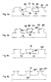
- FIG. 4a shows a steel dowel 60 in the form of a so-called "shark fin".
- the dowel 60 is asymmetrical and has a front 62 and a back 64. They differ by the differently shaped dowel end faces 66, 68.
- the steel dowel 60 On its front side 62, the steel dowel 60 has a claimed undercut in the form of a concave dowel end 66, whereas on its rear side 64, the end face 68 is convex.
- the dowel end 66 passes on the front side 62 with a tip 70 in the horizontally extending dowel top 72, to which the convex dowel step 68 connects directly on its rear side 64 with its convex fillet.
- the asymmetrical design of the anchor 60 has the advantage that the formation of the tip 70 on the dowel top 72 avoids the unfavorable gaping curves, for example, the head bolt, so that an early splitting of the concrete avoided and thus the buoyancy of the dowel joint is not reduced.
- the shape of the "shark fin" in accordance with FIG. 4b be modified.
- the dowel 60 is according to FIG. 4a hatched marked.
- the local dowel back side 64 of the dowel 60 ' shows a convex dowel end face 68'. However, it does not pass into an undercut 76 in the dowel base 74, but by a throat 78 '.
- the radius of the throat 78 on the dowel base 74 reduces the notch effect and also allows non-static stress of the connection.
- the steel surface of the dowel 60 '( FIG. 4b ) smaller than that of the dowel 60.
- the corresponding cross-sectional area for the concrete dowel thus increases with respect to the steel dowel 60 '.
- the dowel shape according to FIG. 4b is asymmetrical and must therefore be aligned according to the thrust flow in the carrier.
- the dowel shape according to Figure 4c By contrast, it is symmetrical and can therefore absorb equal loads in both directions.
- Your dowel end 66 is compared to the previous examples largely straight and is slightly inclined relative to the dowel base 74, it connects to him with a throat 78" on.
- the radius of the groove 78 is significantly greater than in the previously described example, so that the notch effect is further reduced at the dowel base 74.
- the dowel end 66" together with the throat 78 forms an undercut in the sense of the claims.
- a reduction in notch effect can also be achieved and improved by replacing the radius of the throat 78 "with a clothoid, and its curvature increases from the dowel base 74 to the tip 70", thus becoming narrower in this direction of its course shows FIG. 4d on the dowel 60 "'. It is thus cut in a highly concave manner on its two dowel end faces 66", ie the throat 78 "' and the dowel end 66 '" merge seamlessly into one another.
- This embodiment gives the dowel 60 '"compared to the dowel 60" ( Figure 4c ) at the same height a larger contact surface 66 "'. This can reduce the surface pressures there.
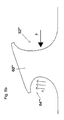
- FIGS. 5a and 5b illustrate schematically a further advantage of the symmetrical dowel 60 '"according to FIG. 4d He is charged on its front side 62 '"by a force P from a first concrete plug, not shown, which engages in the concave dowel end 66'".
- a second convex concrete dowel engages in the likewise concave dowel end 68 "'on the rear side 64'" of the dowel 60 "'. If it is loaded on its front side 62'" by a force P from the first concrete dowel, the steel dowel 60 tilts "'to avoid this load by elastic tilting in the direction of force FIG. 5b exaggerated for clarity.
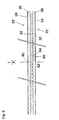
- FIG. 6 shows the basic principle of producing two ourturtloser roll carrier 22 from a rolled origin carrier with double-T or I-profile by a continuous separation cut. It shows two roller carriers 22 with shark fin-shaped dowels 60 in a side view. Their webs 26 are facing each other and engage with their dowels 60 no longer puzzle-like in one another, but are shown pulled apart. By forming a steel dowel 32 on one of the two carriers 22 results in the web 26 space for a concrete dowel on the other support 22 and vice versa.
- the shape of the dowel 60 according to FIG. 4a has the distinct advantage that in the production of a carrier 22 from the rolled double-T or I-profile only a single separating cut is required.
- the asymmetrical dowels 60 are given an orientation by their differently shaped front sides 62 and rear sides 64, which makes it necessary to adapt them to the thrust force profile under load of the steel-concrete composite beams. Since there is a reversal in direction of the thrust force profile in the center of the carrier 80, the orientation of the dowel 60 is correspondingly reversed.
- the different surface distribution of the steel dowel on the one hand and the concrete dowel on the other hand is not only acceptable under normal conditions, but often even desirable, because a larger concrete area is required for a crack-free power transmission in today's conventional concrete qualities.
- the slimmer steel dowel 60 ", 60" ', on the other hand, is usually sufficient to load the forces without damage into the concrete.
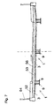
- FIG. 7 shows a road bridge cross-section using three double-layered reinforced concrete beams 1, which were laid in parallel in the bridge longitudinal direction side by side, so that they abut with their upper straps 3 directly to each other.
- the carriers 1 are lifted with a crane into their installation or end position, for which the bridged traffic route only has to be temporarily blocked.
- the upper straps 3 of the three beams 1 now form a continuous surface, which can serve as a formwork for an in-situ concrete slab 50 without much additional effort.
- bridge caps 52 are produced, to which a railing 54 is attached. In the remaining lane area between the bridge caps 52, a road surface 56 is then introduced.
Landscapes
- Engineering & Computer Science (AREA)
- Architecture (AREA)
- Chemical & Material Sciences (AREA)
- Composite Materials (AREA)
- Civil Engineering (AREA)
- Structural Engineering (AREA)
- Bridges Or Land Bridges (AREA)
Applications Claiming Priority (1)
| Application Number | Priority Date | Filing Date | Title |
|---|---|---|---|
| DE200810011176 DE102008011176A1 (de) | 2008-02-26 | 2008-02-26 | Stahl-Beton-Verbundträger und Verfahren zu seiner Herstellung |
Publications (1)
| Publication Number | Publication Date |
|---|---|
| EP2096222A2 true EP2096222A2 (fr) | 2009-09-02 |
Family
ID=40627348
Family Applications (1)
| Application Number | Title | Priority Date | Filing Date |
|---|---|---|---|
| EP09002508A Withdrawn EP2096222A2 (fr) | 2008-02-26 | 2009-02-23 | Support composite en acier-béton et son procédé de fabrication |
Country Status (2)
| Country | Link |
|---|---|
| EP (1) | EP2096222A2 (fr) |
| DE (1) | DE102008011176A1 (fr) |
Cited By (5)
| Publication number | Priority date | Publication date | Assignee | Title |
|---|---|---|---|---|
| EP2431525A1 (fr) * | 2010-09-15 | 2012-03-21 | SSF Ingenieure AG | Construction de pont pour un pont auxiliaire |
| EP2431524A1 (fr) * | 2010-09-15 | 2012-03-21 | SSF Ingenieure AG | Superstructure de pont dotée d'une armature externe |
| CN107023114A (zh) * | 2017-06-19 | 2017-08-08 | 四川大学 | 一种钢和混凝土组合结构的连接件及其构成的组合梁 |
| DE102016217622A1 (de) | 2016-09-15 | 2018-03-15 | Peri Gmbh | Kupplung |
| CN110820514A (zh) * | 2019-11-25 | 2020-02-21 | 西南交通大学 | 用于高速铁路大跨度桥梁的t梁结构及大跨度桥梁 |
Families Citing this family (5)
| Publication number | Priority date | Publication date | Assignee | Title |
|---|---|---|---|---|
| DE102009008826B4 (de) | 2009-02-13 | 2014-12-11 | Ssf Ingenieure Ag | Brücke für Eisenbahnen sowie Längsträger und Verfahren für ihre Herstellung |
| DE102011010672B4 (de) | 2011-02-08 | 2014-10-30 | Ssf Ingenieure Ag | Flächentragwerk mit Verbundplatten |
| DE102011105329B4 (de) * | 2011-06-03 | 2013-06-27 | Areva Np Gmbh | Verbundbauteil und damit hergestellte Stahlbeton-Stahl-Struktur |
| DE102013105243B3 (de) * | 2013-05-22 | 2014-06-26 | Ssf Ingenieure Ag | Trogbrücke mit einer Fahrbahnplatte aus Grobblech und Verfahren zur Herstellung einer Trogbrücke |
| DE102015118241A1 (de) | 2015-10-26 | 2017-04-27 | Ssf Ingenieure Ag | Stahlbeton-Verbundträger und Verfahren zu seiner Herstellung |
Family Cites Families (6)
| Publication number | Priority date | Publication date | Assignee | Title |
|---|---|---|---|---|
| DE3836592A1 (de) * | 1987-10-31 | 1989-05-18 | Kombi Tragwerk Gmbh | Tragwerk |
| DE3738524A1 (de) * | 1987-11-13 | 1989-05-24 | Gernot Wolperding | Verbundtraeger mit stahlsteg |
| LU87137A1 (fr) * | 1988-02-19 | 1989-09-20 | Arbed | Poutre mixte noyee dans le plancher |
| CA2003060A1 (fr) * | 1988-11-16 | 1990-05-16 | Pierre Trouillet | Procede de solidarisation d'une masse de matiere a un support fonctionnel et dispositifs ainsi obtenus |
| DE29505968U1 (de) * | 1995-03-25 | 1995-08-10 | Brendel, Irmfried, Dipl.-Ing., 79410 Badenweiler | Stahlverbundträger |
| AU2719399A (en) * | 1998-02-18 | 1999-09-06 | Schmitt Stumpf Fruhauf Und Partner Ingenieurgesellschaft Mbh | Composite prefabricated girder and a method for manufacturing girders, especially for the construction of bridges |
-
2008
- 2008-02-26 DE DE200810011176 patent/DE102008011176A1/de not_active Withdrawn
-
2009
- 2009-02-23 EP EP09002508A patent/EP2096222A2/fr not_active Withdrawn
Non-Patent Citations (1)
| Title |
|---|
| "Betonkalender", vol. 11, 2002, VERLAG ERNST & SOHN, article "Verbundbrücken in der Praxis" |
Cited By (5)
| Publication number | Priority date | Publication date | Assignee | Title |
|---|---|---|---|---|
| EP2431525A1 (fr) * | 2010-09-15 | 2012-03-21 | SSF Ingenieure AG | Construction de pont pour un pont auxiliaire |
| EP2431524A1 (fr) * | 2010-09-15 | 2012-03-21 | SSF Ingenieure AG | Superstructure de pont dotée d'une armature externe |
| DE102016217622A1 (de) | 2016-09-15 | 2018-03-15 | Peri Gmbh | Kupplung |
| CN107023114A (zh) * | 2017-06-19 | 2017-08-08 | 四川大学 | 一种钢和混凝土组合结构的连接件及其构成的组合梁 |
| CN110820514A (zh) * | 2019-11-25 | 2020-02-21 | 西南交通大学 | 用于高速铁路大跨度桥梁的t梁结构及大跨度桥梁 |
Also Published As
| Publication number | Publication date |
|---|---|
| DE102008011176A1 (de) | 2009-09-03 |
Similar Documents
| Publication | Publication Date | Title |
|---|---|---|
| EP2096222A2 (fr) | Support composite en acier-béton et son procédé de fabrication | |
| AT524664B1 (de) | Verfahren zur Herstellung einer Brücke aus Fertigteilträgern und Fahrbahnplattenelementen | |
| EP2143843A2 (fr) | Auge composite en acier-béton formant tablier de pont et son procédé de fabrication | |
| EP0755473B1 (fr) | Bande a goujons pour barres relevees | |
| EP2218825B1 (fr) | Poutre pour pont pour voies ferrées et sa procédée de fabrication | |
| EP0499590A1 (fr) | Elément connecteur isolant pour planchers de balcon et l'usage de cet élément | |
| EP3574160B1 (fr) | Élément de construction hybride en béton poreux | |
| EP0023042B1 (fr) | Elément de plancher préfabriqué pour planchers de bâtiments | |
| WO2010105594A1 (fr) | Support constitué d'un profilé en acier d'un seul tenant | |
| DE2247609B1 (de) | Verfahren zum herstellen eines brueckenbauwerks aus spannbeton im abschnittsweisen freien vorbau | |
| DE69420001T2 (de) | Methode zum herstellen einer vorgespannten verbundbalkenstruktur | |
| DE102007003552B3 (de) | Brückentragwerk mit Stahl-Beton-Verbund im Untergurtbereich | |
| DE10140733A1 (de) | Brücke und Verfahren zur Herstellung einer Brücke | |
| EP0589401A1 (fr) | Procédé et dispositif pour le démontage et le montage de ponts | |
| DE19831984C2 (de) | Bauteil mit externen Spanngliedern | |
| DE4109052A1 (de) | Leichtbauprofil | |
| WO2023089058A1 (fr) | Construction de dalle de béton comprenant un élément d'assemblage en béton pour assembler des dalles de béton et procédé de fabrication d'une construction de dalle de béton | |
| DE102011009544A1 (de) | Aus einem gewalzten einstückigen Stahlbauprofil bestehender Biegeträger | |
| DE102015118241A1 (de) | Stahlbeton-Verbundträger und Verfahren zu seiner Herstellung | |
| DE2153495A1 (de) | Fertigteildeckenplatte fuer den montagebau | |
| DE1584309A1 (de) | Verfahren zur Herstellung eines Spannbeton- oder Stahlbetontraegers und danach hergestellter Traeger | |
| DE19903310A1 (de) | Verbundfertigteilträger sowie Verfahren zur Herstellung von Trägern, insbesondere für Brückenbauwerke | |
| DE4131214A1 (de) | Brueckenkonstruktion und verfahren zum herstellen einer bruecke | |
| EP0826848B1 (fr) | Dispositif pour l'introduction concentrée d'efforts dans le béton | |
| EP0796961A1 (fr) | Système d'armature pour éléments en béton cellulaire |
Legal Events
| Date | Code | Title | Description |
|---|---|---|---|
| PUAI | Public reference made under article 153(3) epc to a published international application that has entered the european phase |
Free format text: ORIGINAL CODE: 0009012 |
|
| AK | Designated contracting states |
Kind code of ref document: A2 Designated state(s): AT BE BG CH CY CZ DE DK EE ES FI FR GB GR HR HU IE IS IT LI LT LU LV MC MK MT NL NO PL PT RO SE SI SK TR |
|
| AX | Request for extension of the european patent |
Extension state: AL BA RS |
|
| RIN1 | Information on inventor provided before grant (corrected) |
Inventor name: SEIDL, GUENTER |
|
| RIN1 | Information on inventor provided before grant (corrected) |
Inventor name: SEIDL, GUENTER |
|
| RAP1 | Party data changed (applicant data changed or rights of an application transferred) |
Owner name: SSF INGENIEURE AG |
|
| STAA | Information on the status of an ep patent application or granted ep patent |
Free format text: STATUS: THE APPLICATION IS DEEMED TO BE WITHDRAWN |
|
| 18D | Application deemed to be withdrawn |
Effective date: 20120901 |